LG A005KEEN261 User manual

ENGLISH
www.lg.com/b2b
MANUAL
Energy Storage
System
Please read this manual carefully before installing
your equipment and retain it for future reference.
MODEL
A005KEEN261
D007KEEN261
Copyright © 2019 LG Electronics Inc. All Rights Reserved.
19/02/2019

Getting Started2
Getting Started
1
IMPORTANT SAFETY INSTRUCTIONS
General safety instructions
This manual contains important instructions for the installation and maintenance of the LG
Electronics ESS inverter.
LG Electronics ESS inverters are designed and tested to meet all applicable North American
and International safety standards. However, like all electrical and electronic equipment, safety
precautions must be observed and followed during installation and operation of the LG Electronics
ESS inverters to reduce the risk of personal injury and to ensure a safe installation.
Installation, commissioning, service, and maintenance of LG Electronics ESS inverters must only
be performed by qualied personnel who are licensed and/or satisfy state and local jurisdiction
regulations.
Before starting installation or commissioning of the LG Electronics ESS models, read through the
entire manual and note all precautionary statements.
All US electrical installations must comply and be in accordance with all state, local and utility
regulations, and National Electrical Code ANSI/NFPA 70.
Installations in Canada, must be done in accordance with applicable Canadian standards.
Safety symbols and terminology
DANGER DANGER indicates a hazardous situation which will result in
death or serious injury if not avoided.
WARNING WARNING indicates a hazardous situation which could result
in death or serious injury if not avoided.
CAUTION CAUTION indicates a hazardous situation which could result
in minor or moderate injury if not avoided.
NOTICE NOTICE indicates a situation that can result in property
damage if not avoided.
INFO INFORMATION indicates a note of important information
that will ensure optimal operation of the system.
HIGH VOLTAGE WARNING! Indicates hazardous high voltages are present which
will result in death or serious injury if not avoided. Thus, only authorized and
trained personnel should install and/or maintain this product.
Getting Started

Getting Started 3
Getting Started
1
Hot surface
Equipment grounding conductor (PE)
Wait for a prescribed amount of time before engaging in the indicated action.
Safety Instructions
The LG Electronics ESS inverter installation must be performed by an authorized electrician in
accordance with local and National Electrical Code ANSI/NFPA 70 and OSHA requirements.
yThe inverter section contains no user-serviceable parts. For all service and maintenance, the
inverter should be returned to a LG Electronics Authorized Service Center.
yRead all of these instructions, cautions, and warnings for the LG Electronics ESS inverter and
associated ESS equipment (PV panel, RSD, Battery pack, ATS, Energy meter, etc.) documentation.
yApproval must be received by the appropriate local utility as required by national and state
interconnection regulations before connecting the LG Electronics ESS inverter to the AC
distribution grid.
yThe LG Electronics ESS inverter must be connected only by qualied personnel.
yDuring operation, the inverter wiring and connections can have hazardous high voltages
and currents present. Only authorized and qualied personnel shall install and/or perform
maintenance on the inverter.
yThe inverter chassis and heat sink may become hot during certain operations.

Table of Contents4
Table of Contents
Getting Started
IMPORTANT SAFETY INSTRUCTIONS ............................................2
General safety instructions ..........................................................2
Safety symbols and terminology......................................................2
Safety Instructions ..................................................................3
Introduction ..................................................................6
System .............................................................................6
Equipment overview.................................................................9
Inverter type and safety labels ......................................................10
Installation
Installation..................................................................13
General safety .....................................................................13
Visual inspection ...................................................................14
Installation location ................................................................15
Electrical connections.........................................................18
General safety .....................................................................18
Utility AC voltage ..................................................................19
AC circuit breaker requirements .....................................................21
Grounding electrode conductor (GEC) ...............................................21
Lightning and surge protection ......................................................21
PV string considerations ............................................................22
Inverter connections ...............................................................23
Opening the wiring box cover .......................................................24
Wiring box conduit plugs ...........................................................25
PV array string input connections (Only for DC-coupled type)..........................27
PV switch LOCK out and TAG out procedure..........................................29
Battery wire connections ...........................................................30
Battery communication cable connection ............................................31
Battery pack connections ...........................................................32
Energy meter connections ..........................................................34
Energy meter connections (Inverter Side) ............................................37
Inverter AC output wire connections.................................................38
ATS wire connections...............................................................41
Inverter communication connections.................................................43
Wi-Fi antenna connection ..........................................................45

Table of Contents 5
1
2
3
4
Operation
Connecting to a mobile device ..................................................46
Installing 'LG EnerVu2 Professionals' App ............................................46
About the main screen .............................................................46
Connect via Bluetooth..............................................................47
Network Configuration .............................................................49
ESS system settings................................................................50
Registering the PCS (Mobile App) ...................................................51
Commissioning the PV system ..................................................52
LED Indication .....................................................................52
Button ............................................................................55
Inverter turn-on procedure..........................................................56
Inverter turn-off procedure .........................................................56
Appendix
Maintenance ................................................................57
Production information .............................................................57
Repair .............................................................................57
Decommissioning ..................................................................57
Inspecting regularly ................................................................58
Disposing of the product............................................................58
Contact ...........................................................................58
Troubleshooting....................................................................59
LGE Open Source Software Notice ..............................................61
Specifications ...............................................................62
FCC compliance information ...................................................66
[USA] .............................................................................66
[CANADA]. . . . . . . . . . . . . . . . . . . . . . . . . . . . . . . . . . . . . . . . . . . . . . . . . . . . . . . . . . . . . . . . . . . . . . . . .67
Glossary ....................................................................69

Getting Started6
Getting Started
1
Introduction
The LG Electronics ESS inverter not only meets the safety requirements of UL 1741, but also
complies with the specications for Grid Support Utility Interactive Inverters that support a more
stable utility grid.
In the following technical description, the precise functions are explained to the installer, as well
as the user, which are required for the installation, operational start-up and handling of the LG
Electronics ESS inverter.
With this device, you have acquired an LG Electronics ESS inverter for connection of energy storage
and/or photovoltaic systems to your grid. This LG Electronics ESS inverter is characterized by an
advanced housing design and state-of-the-art high-frequency technology, which enable the highest
levels of efciency .
The LG Electronics ESS inverter includes advanced controls, such as anti-islanding protection, and
communicates through an RS485 (EIA485) interface.
The LG Electronics ESS inverter is usable indoors and outdoors. It fullls the directives of ANSI/NFPA
70, UL 1741, UL 1741 SA, IEEE 1547 and IEEE 1547.1 for parallel operation of power generation
plants on low-voltage networks of regional electrical utility companies.
The function of the anti-islanding protection (automatic isolation point for in-plant generation
systems) stipulates compliance with the specications of UL1741, UL 1741 SA and IEEE 1547.
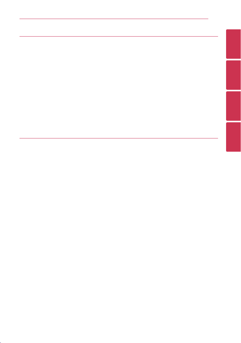
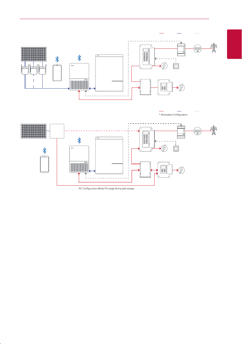
System
In the following description, the precise functions are explained to the installer, as well as the user,
which are required for the installation, operational start-up and handling of the LG Electronics ESS
inverter.
The LG Electronics ESS inverter converts direct current from the solar cells into alternating current.
This enables you to feed your self-produced solar energy into the public grid.
The efcient maximum power point tracking and maximum capacity utilization of the solar energy
plant is ensured even in cases of cloudy skies.
The string concept means that PV modules are always connected in series (in a string) and/or that
strings with the same voltage are connected in parallel to the LG Electronics ESS inverter with the
aim of signicantly reducing the photovoltaic system’s cabling requirements.
The fact that the modules are connected in strings also means that the photovoltaic system can be
perfectly matched to the LG Electronics ESS inverter’s input voltage range.
The inverter is a transformerless type without galvanic isolation. Therefore, the inverter may only
be operated with ungrounded PV arrays. Furthermore, the PV array must be installed in accordance
with locally valid regulations for ungrounded PV arrays. Additionally, the PV array (PV modules and
cabling) must have appropriate protective insulation, and the PV modules used must be suitable for
use with this inverter. PV modules with a high capacity to ground may only be used if their coupling
capacity does not exceed 1,200 nF with 60 Hz grid.

Getting Started 7
Getting Started
1
DC 7.6kW
Main Panel
Protected
Sub-Panel
RS 485 communication
ATS
Fireman
switch
Main Load
Protected
Load
Energy Meter
Split phase
240V
3-String
RSD Box
AC Power DC Power Communication
Installation
By mobile app.
Main Panel
Protected
Sub-Panel
RS 485 communication
Not allowing PV usage during off-grid mode
※
A detailed description of the AC configuration allows PV usage during grid outage is provided in the appendix.
1)
2)
Protected
Load
Energy Meter
AC Power DC Power Communication
1) 2)
AC 5kW
Installation
By mobile app.
Existing Solar system Or LG AC Module
Auto-TX
Switch Box
Fireman
switch
Main Load
Split phase
240V
PV inverter
< System Overview >
PV modules
For the DC-coupled system, the PV modules work in MPPT mode or power reduction mode
according to system operational mode. The maximum number of PV strings is three. For the AC-
coupled system, there is the option to have no solar modules connected to the LG Electronics ESS
inverter at all, and the PV power option will be deactivated.
Battery Pack
The Battery Pack can store surplus energy generated from rooftop solar modules for use when
needed. When the sun has set, energy demand is high, or there is a black-out, you can use the
energy stored in your Energy Storage System to meet your energy needs at no extra cost. Unlike
a grid-tied solar system which automatically switches off, a battery storage system allows you to
keep generating and consuming energy when the grid goes down.
RSD
The RSD provides an automatic disconnect of residential or small commercial PV systems, fully
compliant with the Rapid Shutdown requirements of NEC 2014 Article 690.12.

Getting Started8
Getting Started
1
ATS
The auto transfer switch (ATS) is an electrical device that switches the home’s load between grid
power and backup power. The ATS is automatically triggered when it senses the grid has been lost/
restored.
Meter
The Meter is used by the inverter for import / export or consumption readings, and manages the
battery charge / discharge accordingly for smart energy management applications, including self-
consumption, zero export or Time of Use Rates (TOU). The meter communicates with the inverter
via RS485.
Grid
240 V and 208 V grid are supported. This can be congured via the mobile App.
Android/iOS APP
A powerful tool for monitoring, conguration or diagnostics, the App is connected to the inverter via
Bluetooth.
LG Electronics Cloud
The inverter communicates with the LG Electronics cloud via a WiFi gateway installed within the
inverter. Also, the WiFi gateway can push data directly to the customer’s cloud or third-party cloud.

Getting Started 9
Getting Started
1
Equipment overview
< Exterior view of inverter main components >
aInverter Power Box - This is the inverter section of the assembly. This section is sealed at the
factory and there are no user-serviceable parts inside. All wiring to install the inverter is done in
the wiring box.
bWiring Box Cover - This is the cover for the wiring compartment. Please note the DC disconnect
must be in the OFF position before this cover can be removed.
cLED Lights - The five LED lights indicate errors or status.
dMounting Plate - The inverter comes with a mounting plate that allows easy assembly of the
inverter to a wall.
eWiring Box - This is the compartment where all the wiring for the inverter inputs and outputs
plus the RS485 communication are done.
fConduit Plugs - There are 5 - 3/4“ conduit openings and 2 - 1/2“ conduit openings. Each
conduit opening comes fitted with a conduit plug that should be removed before installing
conduit fittings. Conduit fittings need to be watertight with either NEMA 4, 4X, 6, or 6X rated,
and an insulated type is preferred.
yThe DC Disconnect is shown with the lock in the OFF position. There is an opening on the
disconnect where a padlock can be attached.

Getting Started10
Getting Started
1
Inverter type and safety labels
The type label is shown in the gure. below. Different type labels can be found on the models. The
inverter serial number can be found here. Please note that capital letters in Serial Number are used
as placeholders to indicate the variable information for the LG Electronics ESS.
The main caution labels in English and French are on the right side of the inverter.
Date
<Location of type label>

Getting Started 11
Getting Started
1
3.54”
6.32” (160.5 mm)
9.84” (250 mm) 13.38“ (340 mm)
23.23” (590 mm)
16.73” (425 mm)
(90 mm)
2.77”
(70.5 mm)
< Dimensions of ESS inverters >

Getting Started12
Getting Started
1
< Wiring box of inverters >
aPV and Battery terminals
bBAT Fuse Holders
cGrounding
dAC terminal
eRS485 communication ports
fCAN and RS485 communication ports
gEthernet and RS485 communication ports
Required torques for wiring box terminals
Terminals Wire size permitted* Torque
3 (Grounding) 10 - 8 AWG 16 in-lbs
* Exception: Specified torque marked on the terminal block. All other terminals are spring type.

Installation 13
Installation
2
Installation
General safety
WARNING
Please read all of these instructions, cautions, and warnings for the LG Electronics ESS inverter
and associated PV array documentation.
WARNING
Installation and commissioning must be performed by a licensed electrician in accordance with
local, state, and National Electrical Code ANSI/NFPA 70 requirements.
WARNING
The installation and wiring methods used in the installation of this inverter in the U.S. must comply
with all US National Electric Code requirements (NEC) and local AHJ inspector requirements. In
Canada, the installation and wiring methods used must comply with the Canadian Electric Code,
parts I and II, and the local AHJ inspector requirements. System grounding when required by the
Canadian Electrical Code, Part 1, is the responsibility of the installer.
CAUTION
The secondary short-circuit current rating is increased at the transfer connection point to the
public electricity supply system by the nominal current of the connected ESS inverter.
CAUTION
To reduce the risk of re, connect only to a circuit provided with branch circuit overcurrent
protection in accordance with the National Electrical Code, ANSI/NFPA70.
Installation

Installation14
Installation
2
Visual inspection
All LG Electronics ESS inverters are 100 % tested, packaged in a heavy duty cardboard shipping
carton, and visually inspected before leaving our manufacturing facility. If you receive the inverter in
a damaged shipping carton, please reject the shipment and notify the shipping company. Verify that
the LG Electronics ESS shipping carton contains:
a. Correct inverter model name
b. Mounting plate
c. Manual
d. Wi-Fi antenna
Visually inspect the LG Electronics ESS inverter for any physical damage such as a bent heatsink n
and dented chassis.
If the inverter appears to be damaged or if the inverter needs to be returned, please contact your
local LG Electronics representative.
WARNING
No user serviceable parts are contained in the inverter section. Do not attempt to
open or repair the inverter. The inverter section is factory sealed to maintain its Type 4
rating. Opening the top cover of the power head will void the inverter warranty.

Installation 15
Installation
2
Installation location
yInstall the inverter on a non-ammable support base.
yThe inverter must be mounted vertically on a at surface.
yA minimum distance of 6” (15.2 cm) of unobstructed clearance between the inverter and
other equipment and 4” (10 cm) between the inverter and a corner is required to promote free
convection.
yEnsure the mounting hardware and structure can support the weight of the inverter.
yEnsure the mounting hardware meets the appropriate building code.
yAvoid installation on resonating surfaces (light construction walls etc.).
yInstallation can be indoors or in protected outdoor areas.
yAvoid direct sun exposure.
yEnsure ambient temperature is within -22 °F to +149 °F (-30 °C to +65 °C) for optimal
efciency of the system.
yDespite having a Type 4 enclosure with a soiling category III certication, the inverter must not be
exposed to heavy soiling.
yUnused connectors and interfaces must be covered through sealing connectors.
< Mounting directions >
Please make sure the inverter is installed vertically, especially if it is to be installed outdoors.

Installation16
Installation
2
Inverter should be mounted
at least 39” (100 cm) from
the floor or ground surface.
Inverter should be at least
20” (50.8 cm) from any
ceiling surface
>= 4” (10 cm) >= 6” (15.2 cm) >= 6” (15.2 cm)
>= 20” (50.8 cm)
>= 39” (100 cm)
< Inverter clearances >
The National Electric Code may require signicantly larger working clearances (see NEC Section
110.26)
4. 72” ( 120 mm)
2. 09”
(53 mm)
5. 91“ ( 150 mm)
2. 09”
(53 mm)
1. 97”
(50 mm)
1. 50”
(38 mm)
0. 256“
(6.5 mm)
6. 88” (174.8 mm)
< Dimension drawing of mounting plate >
AMount the mounting plate to the wall with at least 4 screws and anchors (Ø 1/4“ (6mm)). You
can use the mounting plate as a template for marking the positions of the boreholes.
BTighten the screws firmly to the wall.

Installation 17
Installation
2
M6 * 2
< Installing the plate and inverter on a wood stud wall >
AUsing the mounting plate as a template, mark four screw holes onto the wall. For 16" (40.6 cm)
on center stud mounting, use the four holes that are indicated for this purpose in the figure.
Make sure at least two of the holes are in the center of a stud before marking the drill location.
BAfter marking the screw hole locations, drill the pilot holes for the appropriate screw type
that will hold the weight of the inverter in the selected material. 1/4“ (6 mm) lag bolts are
recommended for mounting on wood framed walls.
CAlign the mounting plate over the pilot holes and install the mounting hardware to the
mounting surface. Please tighten to the recommended torque necessary to hold the mounting
plate firmly to the wall surface type.
DAs the inverters are heavy, they should be lifted out of the cardboard container by at least two
persons.
EWith at least one person on each side of the inverter, lift it up and place it carefully onto the
mounting plate. Install two screws in the bottom bracket on the inverter to secure the device.
FCheck that the inverter is seated securely on the wall.
It is recommended to use stainless steel screws, especially if installed outdoors. Verify sheer and
pull-out strength of anchors or other wall attachments.

Installation18
Installation
2
Electrical connections
General safety
DANGER
PV solar arrays produce hazardous voltages and currents when exposed to light, which
can create an electrical shock hazard. Use dark opaque sheets to cover the PV solar
array before wiring or connecting cable terminations.
WARNING
Read all of these instructions, cautions, and warnings for the inverter and associated PV array.
WARNING
Installation and commissioning must be performed by a licensed electrician in accordance with
local, state, and National Electrical Code ANSI/NFPA 70 requirements. Use 10 AWG or greater
90°C (194 °F), copper solid or stranded wire for all DC and AC wiring to the inverter to optimize
system efciency .
WARNING
Before connecting the inverter to the AC distribution grid, approval must be received by
appropriate local utility as required by national and state interconnection regulations. The inverter
must be connected only by qualied personnel.
CAUTION
Do not attempt to open or repair the inverter, as it is factory sealed to maintain Type 4 rating.
Opening the inverter will void the warranty.
CAUTION
The PV input circuits are isolated from the enclosure. The PV system Grounding Electrode
Conductor (GEC) when required by National Electric Code (NEC), ANSI/NFPA 70 Sections 690.41,
690.42, and 690.43 is the responsibility of the installer.

Installation 19
Installation
2
Utility AC voltage
The LG Electronics ESS inverters are grid-tied to the public utility. The inverters are software
congurable via the user display panel for various 208 V AC or 240 V AC 60 Hz public utility grids.
CAUTION
The LG Electronics ESS Inverters should never be connected to a 120 V AC utility service. NEC
705.12 requires that the inverter be connected to a dedicated circuit with no other outlets or
devices connected to the same circuit.
AC connection voltage and frequency limits:
Voltage range for 208 V nominal, line to line 185 V - 226 V
Voltage range for 240 V nominal, line to line 213 V - 262 V
Frequency Range 59.3 Hz - 60.5 Hz
Public grid configuration allowed:
< 240 V / 120 V Split Phase AC Grid > < 208 V Inverter AC Grid >

Installation20
Installation
2
< 208 V / 120 V WYE AC Grid > < 240 V Inverter AC Grid >
< 240 V / 120 V Stinger AC Grid >
Public Grid Configuration NOT Allowed:
< 480 V DELTA AC Grid > < 480 V / 277 V WYE AC Grid >
This manual suits for next models
1
Table of contents
Other LG Inverter manuals

LG
LG LG S1C-G3 Series User manual

LG
LG AP-Q36GRA0 Product guide

LG
LG LG N1C(W)-L5 Series User manual

LG
LG Mono X Plus Series User manual

LG
LG KM113.27UU User manual

LG
LG N1T-V Series User manual

LG
LG N2W-L5 Series User manual

LG
LG SIMs 2.0 User manual

LG
LG LG N1K-N6 Series User manual

LG
LG ACAH020HETB Installation instructions