PDP Training - Fall 2008 3
Table of ConTenTs
OVERVIEW .................................................. 5
Introduction ....................................................5
Basic Troubleshooting Steps...........................5
Caution............................................................5
Model Number Structure ...............................6
Serial Number Structure.................................6
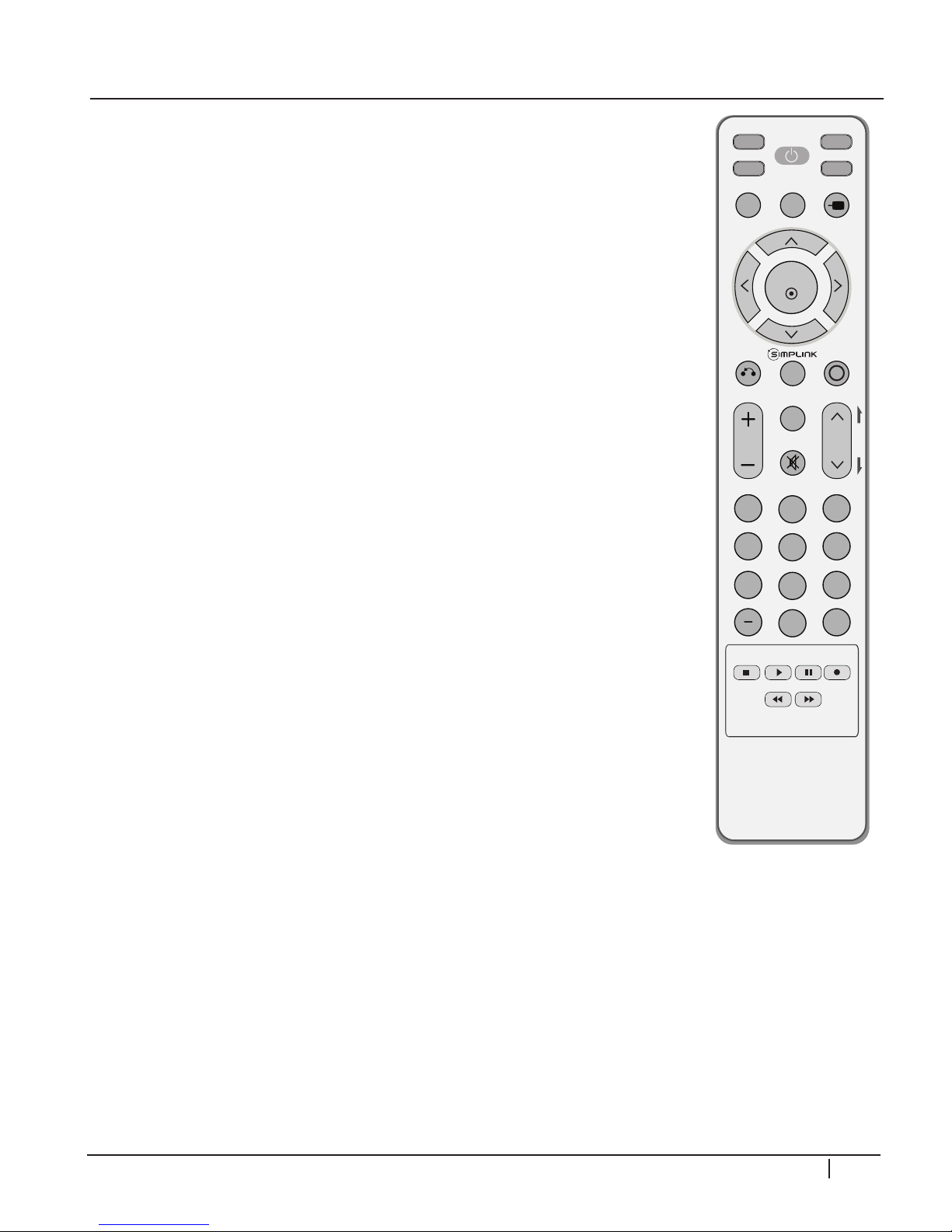
Remote Control ..............................................7
New Features .................................................7
Computer Connection....................................8
Service Menu...................................................8
Power Consumption.......................................8
Service Remote ...............................................9
Check Firmware Version ............................. 10
Update Firmware......................................... 10
42PG20 Dimensions .................................... 11
50PG20 Dimensions .................................... 11
DISASSEMBLY ........................................... 12
Introduction ................................................. 12
Back Cover Removal.................................... 12
Switch Mode Power Supply Removal .......... 13
Y-Sus board Removal.................................... 13
Y-Drive board Removal ............................... 13
Z-Sus board Removal................................... 13
Main board Removal .................................... 13
Control Button Board Removal ................... 13
X-Drive boards Removal.............................. 13
TCP Connector Removal............................. 15
P232 & P331 Connector Removal ............... 15
Control Button board removal .................... 16
42PG20 Exploded View ............................... 17
Block Diagram.............................................. 18
Signal and Voltage Block Diagram ................ 19
CIRCUIT DESCRIPTIONS......................... 20
Introduction ................................................. 20
Adjustment Order **Important**................ 20
Power Supply (SMPS)................................... 21
Y-Sus Board .................................................. 29
Y-Drive Board .............................................. 37
Z-Sus Board ................................................. 42
Control Board.............................................. 44
X-Drive Boards ............................................ 51
Left and Right X-Drive Removal .................. 55
Main (Digital) Board ..................................... 56
Power Switch and Keypad ........................... 61
DISASSEMBLY ........................................... 63
Introduction ................................................. 63
Back Cover Removal.................................... 63
Power Supply Board Removal...................... 63
Y-Sus Board Removal ................................... 64
Top Y-Drive Board Removal......................... 64
Bottom Y-Drive Board ................................. 64
Z-Sus Board Removal................................... 65
Main Board Removal.................................... 65
Control Board Removal ............................... 65
X-Board Removal......................................... 65
TCP connector removal............................... 67
P232 & P331 connector removal................. 67
50PG20 Exploded View ............................... 68
Block Diagram.............................................. 69
Signal and Voltage Block Diagram ................ 70
CIRCUIT DESCRIPTIONS ........................ 71
Introduction ................................................. 71
Adjustment Order **Important**................ 72
Power Supply ............................................... 72
Y-Sustain....................................................... 82
Y-drive .......................................................... 88
Z-Sus Board ................................................. 93
Control Board.............................................. 97
X-Drive Boards .......................................... 102
Left and Right X-Drive Removal ................ 107
Main (Digital) Board ................................... 108
SCHEMATICS .......................................... 111
42PG20 :: Interconnect.............................. 111
42PG20 :: Waveforms ................................ 112
42PG20 :: Main Board :: Video & BCM...... 113
42PG20 :: Main Board :: Control ............... 114
42PG20 :: Main Board :: DDR Memory..... 115
42PG20 :: Main Board :: Tuner................... 116
42PG20 :: Main Board :: Audio Processor . 117
42PG20 :: Main Board :: Power Regulator. 118
42PG20 :: Main Board :: Inputs .................. 119
42PG20 :: Main Board :: HDMI & USB ...... 120
42PG20 :: Power Supply :: PFC & MCU.... 121
42PG20 :: Power Supply :: Multi & Stby..... 122
42PG20 :: Power Supply :: VA & VA .......... 123
42PG20 :: Main Board :: PCB Layout......... 124
42PG20 :: Main Board :: Bottom PCB ....... 125
42PG20 :: Sub Boards :: PCB Layout ......... 126
50PG20 :: Main Board :: Interconnect ....... 127
50PG20 :: Main Board :: Control ............... 128
50PG20 :: Main Board :: Video & BCM...... 129
50PG20 :: Main Board :: Control ............... 130
50PG20 :: Main Board :: DDR Memory..... 131
50PG20 :: Main Board :: Tuner................... 132
50PG20 :: Main Board :: Audio Processor . 133
50PG20 :: Main Board :: Power Regulator. 134
50PG20 :: Main Board :: Interface.............. 135
50PG20 :: Main Board :: HDMI & USB ...... 136
50PG20 :: Main Board :: PCB Layout......... 137
50PG20 :: Main Board :: Bottom PCB ....... 138
50PG20 :: Sub Boards :: PCB Layout ......... 139