LGMG North America Inc. Maintenance Manual
4
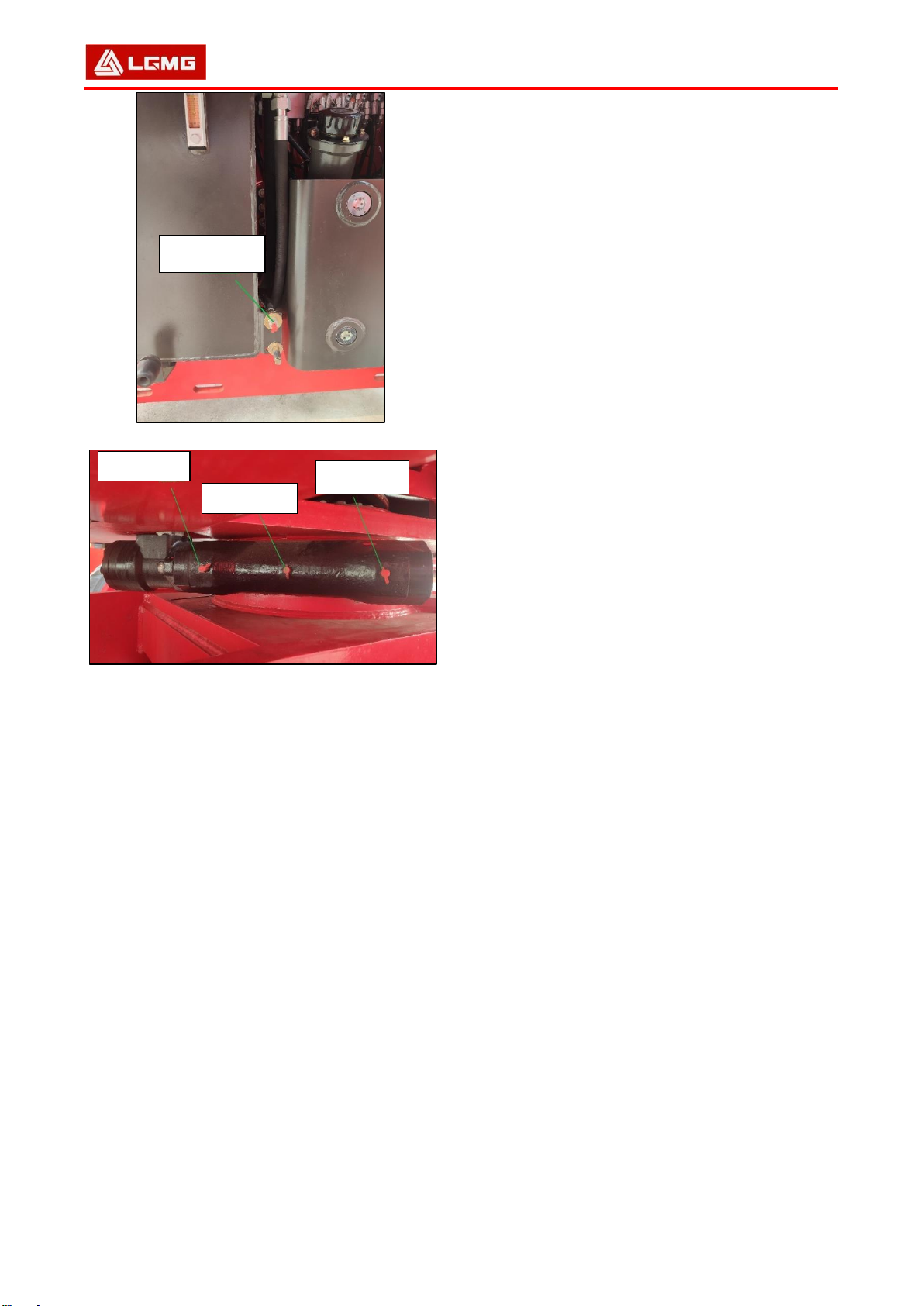
Figure 1-1
1.3.1Maintenance before Delivery
△
!Notice: It refers to the lubrication
of the LGMG platform for working at
heights before delivery.
1) Position 1: Lubrication of the roller path:
The roller path is full and does not need to
be lubricated again.
2) Position 2: Lubrication of the engaging
position between the worm and the slewing
bearing
3) Quantity: It is required to inject 650g of
lubricating grease.
4) Lubrication method: Continuously inject
lubricating grease into the injection port of
lubricating grease while rotating the slewing
reducer
5) Model of the lubricating grease: 3#
lubricating grease
6) Position 3: Lubrication of the tapered roller
bearing: the tapered roller bearing is full
and does not need to be lubricated again.
1.3.2 Market Maintenance
1) Position I: Lubrication of the roller path:
2) Quantity: Proper amount (18g is
recommended)
3) Lubricating frequency: Lubricate every year
or every 1,000 h, whichever occurs first.
4) Lubrication method: Continuously inject
lubricating grease into the injection port of
lubricating grease while rotating the slewing
reducer
5) Model of the lubricating grease: 3#
lubricating grease
1) Position II: Lubrication of the engaging
position between the worm and the slewing
bearing
2) Quantity: Proper amount (It is suggested to
inject a total of 400g of lubricating grease)
3) Lubricating frequency: Lubricate every
three months or every 150 h, whichever
occurs first.
4) Lubricating method: Continuously inject
lubricating grease into the injection port of
lubricating grease while rotating the slewing
reducer
5) Model of the lubricating grease: 3#
lubricating grease
1) Position III: Lubrication of the tapered roller
bearing:
2) Quantity: Proper amount (5g is
recommended at each position, and a total
of 10g for the two positions)
3) Lubricating frequency: Lubricate every year
or every 1,000 h, whichever occurs first.
4) Lubricating method: Direct lubrication
5) Model of the lubricating grease: 3#
lubricating grease
1.4 Checking Hydraulic Oil
Level
Check hydraulic oil level every 8 hours or daily.
Maintaining hydraulic oil at the proper level is
essential for proper machine operation. If the
hydraulic oil is at an appropriate level, hydraulic
components may be damaged. Through daily
inspections, the inspector can determine