manuals.online logo
Brands
  1. Home
  2. •
  3. Brands
  4. •
  5. LI-COR
  6. •
  7. Measuring Instrument
  8. •
  9. LI-COR LI-800 User manual

LI-COR LI-800 User manual

Source, Detector, and Optical Path Replacement
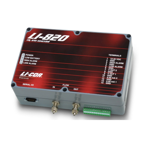
Instructions for the LI-800, LI-820, LI-840, and LI-8100
The LI-800 (discontinued), LI-820, and LI-840 Infrared Gas Analyzers and the LI-8100 Automated Soil CO2Flux System share a
common optical bench configuration; the source and detector on this optical bench can be easily replaced should they fail. These
instructions detail how to change out the source, detector and/or optical bench on any of these four instruments. There is also a
discussion about how to adjust the calibration coefficients and check the linearity of the analyzer’s response (LI-840 and LI-8100
only) at the end of this instruction sheet. Check the table below to make sure that you have the correct replacement part(s) for your
instrument, and then proceed to the appropriate section for installation instructions.
A Phillips head screwdriver and a 1/2” open end wrench are the only tools needed to replace the source and/or detector in all instru-
ments.
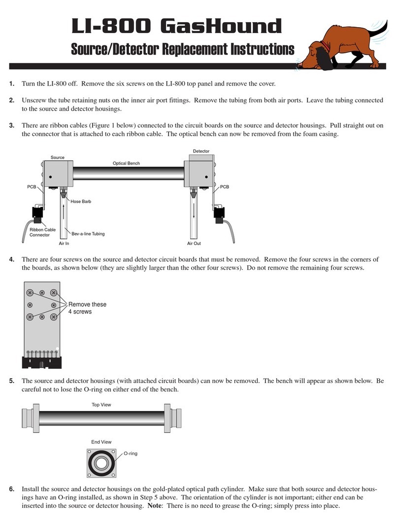
1. Turn the LI-800 off. Let the optical bench cool for about 10
mintues. Loosen the six screws on the LI-800 top panel and
remove the cover.
2. Unscrew the tube retaining nuts on the inner air port fittings.
Remove the tubing from both air ports. Leave the tubing
connected to the source and detector housings.
3. There are ribbon cables (Figure 1) connected to the circuit
boards on the source and detector housings. Pull straight out
on the connector that is attached to each ribbon cable. The
optical bench can now be removed from the foam casing.
LI-800 GasHound CO2Analyzer Source/Detector/Optical Path Replacement
800-902
800-903
800-904
800-905
800-906
8100-902
Source
Detector
Path 14 cm
Path 5 cm
Detector
Source
X
X
X
X
X
X
X
X
X
X
X
X
X
X
Part Number Description LI-800 LI-820 LI-840 LI-8100
LI-800 GasHound CO2Analyzer
LI-820 CO2Analyzer
LI-840 CO2/H2O Analyzer
LI-8100 Automated Soil CO2Flux System
1
1
The LI-800 Replacement Detector retains a default configuration for compatibility with earlier versions of the embedded software.
LI-800 embedded software versions 1.0 and 1.1 are compatible only with the PC Communications Software versions 1.4 and below
(contact LI-COR to upgrade your embedded software). The embedded software version number is printed on a label on the chip
located between the inlet and outlet tubing to the optical bench. To determine which version of the PC Communications Software you
are using, simply start the LI-800 program and view the title bar. If your LI-800 has embedded software version 1.0 or 1.1, proceed
with the instructions below, ignoring Step 11.
Source Detector
Air tube
fittings
Ribbon cable
connector
Ribbon cable
connector
5 cm bench
connector
4. There are four screws on the source and detector circuit
boards that must be removed. Remove the four screws in
the corners of the boards, as shown in Figure 2 (they are
slightly larger than the other four screws). Do not remove
the remaining four screws.
5. The source and/or detector housings (with attached circuit
boards) can now be removed. The optical bench will appear
as shown in Figure 3. Be careful not to lose the O-ring on
either end of the bench. Make sure the optical path tube is
clean (no dust, dirt, etc.) before proceeding.
6. Install the new source and/or detector housings on the gold-
plated optical path cylinder. Make sure that both source and
detector housings have an O-ring installed, as shown in
Figure 3. The orientation of the cylinder is not important;
either end can be inserted into the source or detector
housing. Note: There is no need to grease the O-ring;
simply press into place.
7. Carefully remove the 10-pin connector that was attached to
the old source housing circuit board from the main circuit
board (if the 14 cm bench is being replaced with the 5 cm
bench, or vice versa). Reattach the 10-pin connector to one
of the connectors shown in Figure 4, depending on the
length of the optical bench being installed.
8Install the bench with the source side on the left as you face
the front of the instrument.
9. Reattach the 10-pin connectors to the source and detector
housing circuit boards. Reattach the Bev-a-line tubing to
the flow in and out ports, if necessary.
10. Re-assemble the LI-800 case. Make sure that the foam
insulation on the inside top cover is positioned over the
optical bench; it is required for thermal stability.
11. NOTE: Perform this step only if you have embedded
software version 1.2 or above, and Windows software
version 1.5 or above. Start the 800-50 Windows Communi-
cations Software program (versions 1.5 or higher), and
press the Configure button. Press the Reset LI800 button
(Figure 5). This sets the LI-800 parameters back to the
default values, and loads the calibration polynomial
coefficients.
12. Perform zero and span calibrations as described in the LI-
800 Instruction Manual Section 3, Calibration Window.
2
3
4
2
Remove these 4 screws
Make sure the O-ring
is in place on both ends
of the optical bench (5 cm
bench shown)
LI-800 GasHound
Span:
Alarms:
Filter:
1000 ppm
2000 ppm
5000 ppm
20000 ppm
Enable Alarms
High Alarm
H. Dead Band
Low Alarm
L. Dead Band
IRGA ready. 4/27/99 5:03 PM
Cancel
Reset LI800
OK
10 sec.
1000
100
300
100
✔
Reset button
Controls:
Enable Heater✔
Pressure Compensation
DAC Offset Enable
5
5 cm bench
source connector
14 cm bench
source connector
LI-820 CO2Analyzer Source/Detector/Optical Path Replacement
The LI-820 CO2Analyzer has a standard 14 cm optical bench for making CO2measurements to 2,000 ppm. An optional 5 cm optical
bench can be installed to obtain a resolution of up to 20000 ppm. Please note that early versions of the instrument (embedded)
software (<1.0.5) had a problem related to automatic loading of the calibration coefficients when switching from the long (14 cm)
optical bench to the short (5 cm) optical bench, and vice versa.
To update the embedded software, you must open the LI-820 and install a programming jumper on the main circuit board, and then
run a software update utility to re-program the instrument’s flash memory. Follow the steps below to install a new source, detector,
and/or optical bench in the LI-820; if your instrument serial number is CGA-161 or below, you will need to follow the instructions on
the following page also, to update your instrument software to V1.0.6.
1. Disconnect the LI-820 power supply. Let the optical bench cool
for about 10 minutes. Remove the six screws on the
LI-820 top panel and remove the cover.
2. Unscrew the tube retaining nuts on the inner air port fittings.
Remove the tubing from both air ports. Leave the tubing
connected to the source and detector housings.
3. There are ribbon cables (Figure 1) connected to the circuit
boards on the source and detector housings. Pull straight out on
the connector that is attached to each ribbon cable. The optical
bench can now be removed from the foam casing.
4. There are four screws on the source and detector circuit boards
that must be removed. Remove the four screws in the corners of
the boards, as shown in Figure 2 (they are slightly larger than the
other four screws). Do not remove the remaining four screws.
5. The source and detector housings (with attached circuit boards)
can now be removed. The bench will appear as shown in Figure
3. Be careful not to lose the O-ring on either end of the bench.
Make sure the optical path tube is clean (no dust, dirt, etc.)
before proceeding.
6. Install the source and detector housings on the gold-plated
optical path cylinder. Make sure that both source and detector
housings have an O-ring installed, as shown in Step 3. The
orientation of the cylinder is not important; either end can be
inserted into the source or detector housing. Note: There is no
need to grease the O-ring; simply press into place.
7. Carefully remove the 10-pin connector that was attached to the
source housing circuit board from the main circuit board.
Reattach the 10-pin connector to one of the connectors shown in
Figure 4, depending on the length of the optical bench being
installed.
8Install the bench with the source side on the left as you face the
front of the instrument.
9. Reattach the 10-pin connectors to the source and detector
housing circuit boards. Reattach the Bev-a-line tubing to the
hose barbs on the source and detector housings, and to the flow
in and out ports, if necessary.
10. Re-assemble the LI-820 case. Make sure that the foam insula-
tion on the inside top cover is positioned over the optical bench;
it is required for thermal stability.
12. Perform zero and span calibrations as described in the LI-820
Instruction Manual Section 3, Calibration Window.
3
1
2
3
4
Remove these 4 screws
Source Detector
Air tube
fittings
Ribbon cable
connector
Ribbon cable
connector
5 cm bench
connector
Make sure the O-ring
is in place on both ends
of the optical bench (5 cm
bench shown)
5 cm bench
source connector
14 cm bench
source connector
1. Disconnect the power supply from the LI-820. Remove
the LI-820 top cover by unscrewing the 6 spring-loaded
screws with a Philips head screwdriver.
2. Locate the 2-pin link labeled LK3 on the LI-820 circuit
board; it is located near the optical bench, just above the
LI-COR logo, as shown in Figure 1. Note that there may
or may not be a black connector on one of the pins at
LK3. If a connector is present, it will be placed over only
one pin(the one located on the right side, as the instru-
ment faces you).
3. If there is no black connector at LK3, you will need to
temporarily use a jumper from another location on the
board; make note of which jumper you “borrow” so that
you can replace it after this procedure is completed.
There are 2-pin connectors located at links LK1 and LK2,
as shown in the photo below; use one of these, if neces-
sary. Gently pull the jumper straight up and off of the
pins.
4. Cover both of the pins at LK3 with the jumper.
5. Connect the LI-820 to your computer using the RS-232
cable included with the instrument.
6. Power the LI-820 on.
7. Run the LI-820 software update utility (version 1.0.6).
Click the Update Software button. (The update utility
software can be downloaded from LI-COR’s web site; go
to the LI-820 Product Page and click on Software Down-
loads in the lefthand bar).
8. After the update utility has completed, power off the
LI-820, and replace the jumper. If a jumper was present
at LK3, cover only the one pin on the right side (as the
instrument faces you); if you borrowed a jumper from
LK1 or LK2, replace it.
9. Re-assemble the LI-820 case.
LK3
LK2
LK1
4
Updating the LI-820 Instrument Software (optional)
1
2
LI-820 instrument (embedded) software version 1.0.5 or above is required to fix a problem related to automatic loading of the
calibration coefficients when switching from the long (14 cm) optical bench to the short (5 cm) optical bench, and vice versa.
1. Turn the LI-840 off and remove the power source. Allow the
instrument optical bench to cool for about 10 minutes. Loosen the
six screws on the LI-840 top panel and remove the cover.
2. Unscrew the tube retaining nuts on the inner air port fittings with a
1/2” open end wrench (Figure 1). Remove the tubing from the air
port(s). Leave the tubing connected to the source and/or detector
housings; the old source and/or detector and attached tubing will be
discarded.
3. There are ribbon cables (Figure 2) connected to the circuit boards
on the source and detector housings. Pull straight out on the
connector that is attached to each ribbon cable. The other end of
the ribbon cable can remain attached to the main circuit board. The
optical bench can now be lifted away from the foam casing.
4. There are four screws on the source and detector housings that
must be removed. Remove only the screws from the assembly you
are replacing. Remove the four screws in the corners of the source
circuit board, as shown in Figure 3 (they are slightly larger than the
other four screws). Do not remove the remaining four screws.
Remove the four screws from the shield over the detector housing
(Figure 4). Note that there are four standoffs on the back side of
the screws, inside the shield.
5. The source and/or detector housing (with attached circuit board and
tubing) can now be removed and discarded. Make sure the optical
bench tube is clean (no dust, dirt, etc.) before proceeding.
6. The new source goes on the left side of the optical bench as you
face the instrument (Figure 1); the detector goes on the right side.
Make sure that both source and detector housings have an O-ring
installed. The orientation of the optical path cylinder is not
important; either end can be inserted into the source or detector
housing. Note: There is no need to grease the O-ring; simply press
into place.
7. There are spare pre-formed pieces of Bev-a-line tubing included
with your instrument. Attach the long end of the pre-formed tubing
to the hose barb on the new source (or detector). The new tubing is
stiff, and can be difficult to push onto the hose barbs and inner air
port fittings. Re-attach the source and/or detector housing to the
optical bench using the 4 screws removed in step 4. Attach the
other end of the pre-formed tubing to the inner air port fitting(s).
Re-attach the ribbon cable connector to the source and/or detector
housing circuit board(s). Replace the optical bench assembly in the
foam enclosure.
8. Re-assemble the LI-840 case. Make sure that the foam insulation
on the inside top cover is positioned over the optical bench; it is
required for thermal stability.
9. Perform zero and span calibrations as described in the LI-840
Instruction Manual, Section 3, Calibration Window. Read the
calibration considerations at the end of this document.
LI-840 CO2/H2O Analyzer Source/Detector/Optical Path Replacement
4
Remove the 4
screws on the
detector
housing circuit
board
Standoffs
3
Remove these
4 screws on
the source
housing circuit
board
2
Pull straight
out on the
ribbon cable
connector(s)
1
Source Detector
Tube retaining
nuts
Pre-formed
tubing
5
NOTE: Make sure that you are properly grounded to avoid any
electro-static discharge events that can damage the internal
components.
1. Power the instrument off and remove the battery or other
external power source. Allow the instrument optical bench to
cool for about 10 minutes.
2. Open the Analyzer Control Unit case and remove the access
panel by loosening the 4 thumbscrews.
3. Remove both air filters (Figure 1) by pressing the orange part
of the quick-connect fittings toward the white part of the
connector and pulling the filter out. Discard the filters; there
are replacement filters included that can be used during re-
assembly.
4. There are 3 electrical connectors that must be removed. Two
of them are on a single wiring harness, just to the right of
filter connectors shown in Figure 2; the third is at the left end
of the bundle of blue cables, as shown in Figure 2. Pull
straight out on the connectors to remove them.
5. Remove the 5 screws from the top of the air manifold, as
shown in Figure 3.
The top half of the manifold rests on two pins; lift the top half
until it is completely separated from the bottom half. It is not
necessary to remove any of the hoses.
6. Remove the 12 screws around the outer edge of the white
panel, as shown in Figure 4.
7. Lift the analyzer control unit from out of the yellow case.
Turn the control unit upside down.
8. Remove the 6 screws from the optical bench cover, as shown
in Figure 5.
9. Leave the hoses connected to the optical bench, and lift the
bench out of the foam casing.
10. There are four screws on the source and detector housings
that must be removed. Remove only the screws from the
assembly you are replacing. Remove the four screws in the
corners of the source housing circuit board, as shown in
Figure 6. Do not remove the remaining four screws.
Remove the four screws from the detector housing cover, as
shown in Figure 7. Note that there are some small standoffs
inserted over the screws behind the cover; tilt the housing
down when removing the cover so these standoffs don’t get
lost.
11. Disconnect the ribbon cable connectors attached to the source
and/or detector housing circuit board, as shown in Figure 8.
LI-8100 Automated Soil CO2Flux System Source/Detector/Optical Path Replacement
6
5
Remove these
6 screws to
access the
optical bench
4
Remove the 12
screws around
the outer edge
of the white
panel
3
Remove the 5
screws from the top
of the air manifold
1
Remove the 2
Balston filters and
discard.
2
Remove these 3
connectors
Calibration Considerations for LI-840 and LI-8100
The 800-906 replacement detector has been burned in and calibrated at the factory, and the resulting calibration coefficients are stored
in a memory device that is part of the detector. After you install the detector on your gas analyzer, however, these calibration coeffi-
cients may need to be adjusted, since a different optical path and source are being used in combination with the new detector (and
because errors can result from the source replacement, also). Please note the following:
●At the minimum, you will need to re-zero the CO2and H2O channels. The zero calibration can vary significantly (simply
disassembling the detector can alter the zero).
●If you have the ability to check and set the span for CO2and H2O, you should do that as well, although they should be reasonably
close.
●If you have two different span gases (or an LI-610 Portable Dew Point Generator for H2O), you might want to check the linearity
of the gas analyzer’s response. That is, after zeroing and spanning at 1500 ppm, for example, see what the unit reads at 300 ppm.
If the reading is off by more than 1.5%, you can adjust the linearity of the gas analyzer. A program (and instructions) named
CalAdjust.exe can be used to adjust the linearity; this program can be found on the CD that shipped with your instrument, or can
be downloaded from LI-COR’s web site; go to the LI-8100 Product Page and click on Software Downloads in the lefthand bar.
We would expect that most units’ linearity will remain within factory specification after a detector change, but there is a chance
that it may be off. If your application requires accuracy better than 1.5% over a wide range of concentrations, then you should
check the linearity.
12. Remove the Bev-a-line tubing connected to the source and/
or detector housing at the quick-connect fitting (Figure 8).
Press down on the orange part of the fitting to remove the
tubing.
13. The source and/or detector housing, with attached circuit
board and tubing can now be removed and discarded.
Note that there are O-rings on each end of the optical
bench. It is a good practice to replace the O-ring when
replacing the source. Note: There is no need to grease the
O-ring; simply press into place.
Make sure the optical path tube is clean (no dust, dirt, etc.)
before proceeding.
14. Re-assemble the bench using the replacement source and/
or detector, making sure the O-rings are in place on both
ends of the bench. Note that the orientation of the optical
bench cylinder is not important; either end can be inserted
into the source or detector housing.
15. Re-assemble the LI-8100 case. Make sure that the foam
insulation on the inside top cover is positioned over the
optical bench; it is required for thermal stability.
16. Perform zero and span calibrations as described in Section
5 of the LI-8100 Instruction Manual, User Calibration.
Read the Calibration Considerations at the end of this
document.
7
6
8
Remove the 4
screws on the
detector housing
shield.
Standoffs
Ribbon cable
connector
Bev-a-line tubing
quick connect
Source housing
Detector housing
Remove these
4 screws
7
4421 Superior Street ●P.O. Box 4425 ●Lincoln, Nebraska 68504
International: 402-467-3576 ● FAX: 402-467-2819 ●North America: 1-800-447-3576
In Germany - LI-COR GmbH: +49 (0) 6172 17 17 771
envsales@licor.com ●envsupport@licor.com ●www.licor.com
ACU-101, Rev. 2
®
Using the CalAdjust Program
1. Zero the instrument
The instrument needs to be well zeroed for this correction.
LI-8100 Span Option: Before doing the next two steps, you
may wish to manually set the span value to 1.0000. This is
especially true if you’ve noticed the span values getting progres-
sively worse (0.9, 0.8, etc.). At any rate, whatever the span value
is when you perform this calibration adjustment, that will be the
new “normal” value. (To view and/or adjust the span values in
the LI-8100, navigate to (Palm) Utilities - Calibration, or
(Windows) Utilities - Calibration, then click the Manual tab.)
2. Run CalAdjust.exe
3. Connect the computer to the LI-840 or LI-8100, if necessary
Set the appropriate radio button, set the Com (serial) port, and
click Connect (Figure 1).
4. Measure the first concentration (or dewpoint)
Make a note of the measured and true values, and also the bench
temperature, and (if doing water) the bench pressure reading.
The maximum flow rate through the instrument is about 1 liter/
minute.
5. Measure the second concentration (or dewpoint)
Disconnect the first concentration tank and connect the second
concentration. Note the measured and true values. Presumably,
the pressure and temperature will be essentially the same.
6. Enter the measured data
“Actual” (concentration or dew point) is the true value. “Mea-
sured” is what the analyzer indicated. Gas 1 can be either the
higher or lower concentration, it doesn’t matter. When done,
click the Recalculate button (Figure 2).
7. View the results
You will be shown the old and new curves and coefficients,
based on the two points you entered (Figure 3).
8. Click
Apply
If you want to update the instrument with the new coefficients,
click Apply. Otherwise, click Cancel to leave the instrument
unchanged.
Updated in real time
1. Select which gas
2. Adjust if necessary
3. Enter these
4. Click here
1. Select your
instrument
2. Set
3. Click
1
2
3

Other manuals for LI-800

2

This manual suits for next models

3

Other LI-COR Measuring Instrument manuals

LI-COR LI-3100C User manual

LI-COR

LI-COR LI-3100C User manual

LI-COR LI-7820 User manual

LI-COR

LI-COR LI-7820 User manual

LI-COR Li-189 User manual

LI-COR

LI-COR Li-189 User manual

LI-COR LI-870 Guide

LI-COR

LI-COR LI-870 Guide

LI-COR LI7200RS User manual

LI-COR

LI-COR LI7200RS User manual

LI-COR LI-7700 User manual

LI-COR

LI-COR LI-7700 User manual

LI-COR LI-200R User manual

LI-COR

LI-COR LI-200R User manual

LI-COR TriSonica LI-560 User manual

LI-COR

LI-COR TriSonica LI-560 User manual

LI-COR LI-3000C User manual

LI-COR

LI-COR LI-3000C User manual

LI-COR LI-7500 User manual

LI-COR

LI-COR LI-7500 User manual

LI-COR LI-600 User manual

LI-COR

LI-COR LI-600 User manual

LI-COR LAI-2200 User manual

LI-COR

LI-COR LAI-2200 User manual

LI-COR LI-8100A User manual

LI-COR

LI-COR LI-8100A User manual

LI-COR LI-180 User manual

LI-COR

LI-COR LI-180 User manual

LI-COR LI-250 User manual

LI-COR

LI-COR LI-250 User manual

LI-COR LI-820 User manual

LI-COR

LI-COR LI-820 User manual

LI-COR LI-600 User manual

LI-COR

LI-COR LI-600 User manual

LI-COR LI-7810 User manual

LI-COR

LI-COR LI-7810 User manual

LI-COR 4300 User manual

LI-COR

LI-COR 4300 User manual

LI-COR LI-840 Guide

LI-COR

LI-COR LI-840 Guide

LI-COR LI-850 User manual

LI-COR

LI-COR LI-850 User manual

LI-COR LI-8100A User manual

LI-COR

LI-COR LI-8100A User manual

LI-COR LI-6800 User manual

LI-COR

LI-COR LI-6800 User manual

LI-COR LI-800 User manual

LI-COR

LI-COR LI-800 User manual

Popular Measuring Instrument manuals by other brands

Westward 15F218 Operating instructions manual

Westward

Westward 15F218 Operating instructions manual

Omicron C-Probe 1 user manual

Omicron

Omicron C-Probe 1 user manual

Konica Minolta VIVID 9i brochure

Konica Minolta

Konica Minolta VIVID 9i brochure

Extech Instruments SDL470 user manual

Extech Instruments

Extech Instruments SDL470 user manual

Decagon Devices AccuPAR LP-80 Operator's manual

Decagon Devices

Decagon Devices AccuPAR LP-80 Operator's manual

Bosch GLL 2-20 Professional Original instructions

Bosch

Bosch GLL 2-20 Professional Original instructions

Navitel R66 2K user manual

Navitel

Navitel R66 2K user manual

Chauvin Arnoux F 65 user manual

Chauvin Arnoux

Chauvin Arnoux F 65 user manual

E+E Elektronik HUMIPORT 05 manual

E+E Elektronik

E+E Elektronik HUMIPORT 05 manual

Keysight Technologies N5252A user guide

Keysight Technologies

Keysight Technologies N5252A user guide

Hanna Instruments HI 9812-0 instruction manual

Hanna Instruments

Hanna Instruments HI 9812-0 instruction manual

LOVATO ELECTRIC DME D110T1 instruction manual

LOVATO ELECTRIC

LOVATO ELECTRIC DME D110T1 instruction manual

PCB Piezotronics HT356A13/NC Installation and operating manual

PCB Piezotronics

PCB Piezotronics HT356A13/NC Installation and operating manual

KOHTECT qb701 user manual

KOHTECT

KOHTECT qb701 user manual

Saramonic Vmic user manual

Saramonic

Saramonic Vmic user manual

Opsens F2300 Series Instructions for use

Opsens

Opsens F2300 Series Instructions for use

IQAir AirVisual Outdoor manual

IQAir

IQAir AirVisual Outdoor manual

Keller LEO-Record quick start guide

Keller

Keller LEO-Record quick start guide

manuals.online logo
manuals.online logoBrands
  • About & Mission
  • Contact us
  • Privacy Policy
  • Terms and Conditions

Copyright 2025 Manuals.Online. All Rights Reserved.