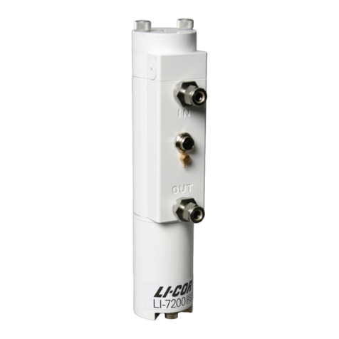
LI-COR li-7200 User manual

Enclosed CO2/H2O
Gas Analyzer
Instruction Manual


LI-7200RS
Enclosed CO2/H2O Gas Analyzer
Global Headquarters
LI-COR Biosciences
4647 Superior Street
Lincoln, Nebraska 68504
Phone: +1-402-467-3576
Toll free: 800-447-3576
Fax: +1-402-467-2819
envsales@licor.com
envsupport@licor.com
www.licor.com/env
Regional Offices
LI-COR GmbH, Germany
Serving Andorra, Albania, Cyprus, Estonia, France, Germany, Iceland,
Latvia, Lithuania, Liechtenstein, Malta, Moldova, Monaco, San Marino,
Ukraine, and Vatican City.
LI-COR Biosciences GmbH
Siemensstrasse 25A
61352 Bad Homburg
Germany
Phone: +49 (0) 6172 17 17 771
Fax: +49 (0) 6172 17 17 799
envsales-gmbh@licor.com
envsupport-gmbh@licor.com
LI-COR Ltd., United Kingdom
Serving Denmark, Finland, Ireland, Norway, Sweden, and UK.
LI-COR Biosciences UK Ltd.
St. John’s Innovation Centre
Cowley Road
Cambridge
CB4 0WS
United Kingdom
Phone: +44 (0) 1223 422102
Fax: +44 (0) 1223 422105
envsales-[email protected]om
envsupport-UK@licor.com
LI-COR Distributor Network:
www.licor.com/env/distributors

NOTICE
The information contained in this document is subject to change without notice.
LI-COR MAKES NO WARRANTY OF ANY KIND WITH REGARD TO THIS MATERIAL, INCLUDING, BUT NOT
LIMITED TO THE IMPLIED WARRANTIES OF MERCHANTABILITY AND FITNESS FOR A PARTICULAR PURPOSE.
LI-COR shall not be liable for errors contained herein or for incidental or consequential damages in connection with the
furnishing, performance, or use of this material.
This document contains proprietary information which is protected by copyright. All rights are reserved. No part of this
document may be photocopied, reproduced, or translated to another language without prior written consent of LI-COR,
Inc.
The LI-7200RS is covered by U.S. Patents 8,154,714; 8,125,626; 8,130,379; 8,300,218 and foriegn equivalents. Other patents
pending.
EddyPro and the SmartFlux System are trademarks of LI-COR, Inc. Microsoft® and Windows® are registered trademarks
of Microsoft Corporation. Eurofast® is a registered trademark of Turck, Inc. Campbell Scientific® is a registered trade-
mark of Campbell Scientific, Inc. Dropbox and the Dropbox logo are trademarks of Dropbox, Inc. All other trademarks
or registered trademarks are property of their respective owners.
Printing History
Publication Number 984-15810
© Copyright 2015 - 2016, LI-COR, Inc.
New editions of this manual will incorporate all material since the previous editions. Update packages may be used
between editions which contain replacement and additional pages to be merged into the manual by the user. The manual
printing date indicates its current edition. The printing date changes when a new edition is printed. (Minor corrections
and updates which are incorporated at reprint do not cause the date to change).
Version Number Publication Date Changes
1st Printing November, 2015 Not applicable.
2nd Printing October, 2016 Updates for the SmartFlux® 2 System
Updated on Friday, February 24, 2017.
ii

iii
CE Marking:
This product is a CE-marked product. For conformity information, contact LI-COR Support at envsupport@licor.com.
Outside of the U.S., contact your local sales office or distributor.
Doc. #53-16033-A
July 7, 2016
page 1 of 1
LI-7200RS Closed Path CO2/H2O Analyzer
Part Name Toxic and Hazardous Substances or Elements
(Pb) (Hg) (Cd) (Cr(VI)) (PBB) (PBDE)
PCBs)
Optics)
Cables and Wires)
(Metal Parts)
(Plastic Parts)
X
X
X
X
X
SJ/T 11364
O = GB/T 26572
(indicates that the content of the toxic and hazardous substance in all the Homogeneous
Materials of the part is below the concentration limit requirement as described in GB/T 26572).
X = GB/T 26572
(indicates that the content of the toxic and hazardous substance in at least one Homogeneous
Material of the part exceeds the concentration limit requirement as described in GB/T 26572).
O
O
O
O
O
O
O
O
O
O
O
O
O
X
O
O
O
O
O
O
O
O
X O O O O O
O
O
O
(Electro-
mechanical Parts)
LI-7200RS CO2 / H2O

A bit of history...
The LI-7200RS model is the followup to the LI-7200, which is the enclosed ana-
lyzer that used technology from the original LI-7500. The LI-7200 began life
with the intention of being a component of homemade eddy covariance sys-
tems, but the built-in datalogging and networking capabilities enabled the
instrument to grow into the core component of a stand-alone, full-featured eddy
covariance system.
The RS models present improvements to the optical hardware, and these
improvements will directly affect the quality of data collected and the cleaning
frequency of optical components.
New instruments will provide a noticeable difference in measurements in many
circumstances. Older instruments can be upgraded to the new hardware. If you
don't want to purchase the upgrade, you can still update your instrument soft-
ware to the most current version—so you are not left behind by the new model
number.
Even if you do not upgrade your instrument hardware, you can use this manual
to guide your use of an original LI-7200. We invite you to install the new soft-
ware on older instruments. It is available for free from the LI-COR web site. We
also invite your feedback—what do you like? What do you dislike? What do you
want to measure that you can't measure now?
iv

v
Contents
A bit of history... iv
Section 1. General Information
What’s What 1-2
Spare Parts Kits 1-2
Cables 1-3
Calibration Certificate 1-5
The SmartFlux® 2 System 1-5
LI-7550 Analyzer Interface Unit 1-6
Section 2. Initial Setup
First Things First 2-1
Installing the Gas Analyzer and Components 2-4
Mounting the LI-7550 Analyzer Interface Unit 2-4
Using the Insulated Intake Tube 2-5
Using the Heated Intake Tube 2-6
Installing the Intake Cap 2-11
Mounting the Sensor Head and Intake Tube 2-12
Tips for Successful Use of the LI-7200RS 2-15
Filtering 2-16
Cleaning 2-16
Vibrations 2-16
Extreme Humidity 2-16
Using the 7550-101 Auxiliary Sensor Interface 2-19
Mounting the ASI 2-19
Terminal Connections 2-20
Electrical Connections 2-21
Connecting Sensors to the ASI 2-21
Section 3. Operation
Installing the PC Software 3-1
Connecting with the Analyzer 3-1
Connect over Ethernet 3-2

Connect over Serial RS-232 3-4
Run Disconnected 3-5
Dashboard 3-6
Instrument Information and Logging 3-7
Instrument Status and Connectivity 3-8
Eddy Covariance Flux Graphs 3-10
Data Display 3-13
Configuring Eddy Covariance Measurements 3-17
Eddy Covariance Checklist 3-18
System Clock 3-21
Configuring the USB Log File 3-22
Entering the Site Description 3-23
Entering Anemometer Information 3-25
Entering CO2/H2O Analyzer Information 3-31
Entering LI-7700 Information 3-37
Entering Biomet System Information 3-39
Connecting with the SmartFlux or SmartFlux 2 System 3-43
Begin Logging Data 3-44
Transferring Logged Data 3-47
Using the SmartFlux System or SmartFlux 2 3-49
Express Processing 3-49
Overview of Advanced Processing 3-50
SmartFlux Results Files 3-60
Section 4. Calibration
How Stable are Zero and Span? 4-1
Checking the Zero 4-2
Checking the Span 4-3
Step-by-Step Calibration Instructions 4-5
Zero H2O 4-7
Considerations for Setting the Secondary Span 4-8
Step-by-Step Secondary CO2 Span 4-8
Step-by-Step Secondary H2O Span 4-9
What Actually Happens 4-9
Section 5. Maintenance
Schedule 5-1
Cleaning the Optical Path 5-2
Opening the Optical Bench 5-3
Replacing the Fuses 5-4
Power Supply Fuse 5-5
Accessory Fuse 5-5
Replacing the Internal Chemicals 5-5
vi

vii
Replacing the Thermocouples 5-8
Leak Test 5-10
Cleaning the Intake Cap and Screen 5-10
Maintaining the Filter 5-11
Section 6. Troubleshooting
Power On Problems 6-1
Problems with the SmartFlux 2 System 6-1
Ethernet Connection Problems 6-2
RS-232 serial connection problems 6-3
Instrument software is unresponsive 6-4
Bad Temperature Readings 6-5
Bad Pressure Readings 6-5
Bad CO2 or H2O Readings 6-6
Section 7. Software Reference
Menu Overview 7-1
Auxiliary Inputs 7-2
Outputs 7-4
Calibration Overview 7-13
Changing Sensor Heads 7-16
Diagnostic Messages 7-17
General indicators 7-17
Test Point Values 7-18
Waveform 7-20
Charting 7-21
PC Logging 7-23
Configuration Files 7-24
Software Updates for Gas Analyzers 7-24
Section 8. Theory of Operation
Relating Absorption to Concentration 8-1
Measuring Absorptance 8-2
Cross Sensitivity 8-3
Zero Drift 8-3
Equation Summary 8-4
LI-7200RS Implementation 8-6
A Note About Pressure And Temperature 8-7
LI-7200RS Diagnostics 8-7

CO2 Signal Strength 8-7
Delta Signal Strength 8-10
LI-7200RS Transfer Functions and Signal Processing 8-11
Signal Processing Bandwidth/Frequency Response 8-11
Appendix A. Specifications
Appendix B. Pin Assignments
Appendix C. Suppliers
Appendix D. Configuration Grammar
Appendix E. Warranty
Appendix F. Index
viii

Section 1.
General Information
The LI-7200RS is a closed path, non-dispersive infrared CO2/H2O analyzer designed
for use in eddy covariance flux systems. Some of the LI-7200RS's important features
include:
Figure 1-1. Components of the LI-
7200RS sensor head.
lOnboard computation of flux data in
the SmartFlux 2 SystemSmartFlux 2
System, which is included as a stand-
ard component.
lSimultaneous, high-speed meas-
urements of CO2and H2O in the
sample cell (150 Hz) are digitally
filtered to provide true 5, 10, or 20 Hz
bandwidth.
lHigh speed measurements of pressure
in the sample cell and air temperature
at the cell inlet and outlet.
lInsulated intake tube and optional
heated intake tube.
lLogging complete eddy covariance data
sets.
The LI-7200RS is designed for eddy cov-
ariance flux measurements, but it is also
suitable for profile measurements, relaxed
eddy accumulation measurements, gradi-
ent flux techniques, pCO2measurement
systems, or any other application that
1-1LI-7200RS Enclosed CO2/H2O Analyzer

Section 1. General Information
depends on high-speed CO2gas or water vapor measurements.
The LI-7200RS computes dry mole fractions of CO2or H2O in the air sample cal-
culated using high speed measurements. These variables account for changes in air
density due to the water vapor content, pressure, and temperature of the sample air.
CO2dry and H2O dry are computed as mole of gas per mole of dry air, and can be
used for computing eddy covariance fluxes without the need for density corrections
(Webb et al., 1980).
Important: There are fine-wire thermocouples that measure air temperature at
the air inlet and outlet ports. Do not insert long objects (e.g., narrow tubing or
screwdriver) into the inlet or outlet ports. Doing so will damage the ther-
mocouples.
What’s What
If you have just taken delivery of your LI-7200RS, check the packing list to verify
that you have received everything that was ordered.
Note: You need the PC software to configure the instrument. Download it from
the LI-COR technical support web site: www.licor.com/env/support. Select your
instrument and you'll find the software downloads.
Spare Parts Kits
The LI-7200RS sensor head spare parts kit (part 7200-028) includes accessories and
replacement parts for the sensor head. The LI-7550 Analyzer Interface Unit also has
a spare parts kit (part 9975-023). It includes the cables and mounting bracket. As
you become familiar with the analyzer you will learn which items to keep close at
hand and which items can be stored away.
Description Qty. Part Number
LI-7200RS Spares Kit 1 7200-028
Bev-a-line Tubing (4.6 m; 15 ft) 1 222-10770
Urethane Tubing (5.2 m; 17 ft) 1 222-00302
3/8-1/4” adapter 1 300-10771
Sensor Head Mounting Post (yellow dampers) 1 9972-046
1-2 LI-7200RS Enclosed CO2/H2O Analyzer

Description Qty. Part Number
Sock Tip Swabs 4 610-05315
Replacement Temperature Thermocouple 2 9972-007
Insulated Intake Tube (1 m) 1 9972-053
Intake Cap Assembly 1 9972-072
Swagelok 2-micron Dust Filter 2 9972-073
Hex Key (7/64") 1 610-03745
LI-7550 Analyzer Interface Unit Spares Kit 1 9975-023
Control Unit Mounting Kit 1 9979-022
RS-232 Cable 1 392-10268
Power Cable 1 9975-030
Analog Input/Output Cable 1 392-10109
Ethernet Cable (8-pin Turck® Connectors; 5 m; 16.4 ft) 1 392-10108
Ethernet Adapter Cable, 8-pin Turck to RJ45 1 392-10107
Standard Ethernet Cable (2.1 m; 7 ft) 1 616-06116
SDM Interface Cable 1 392-10093
5 Amp Fuse 2 439-04214
16 GB USB Flash Drive 1 616-10723
(Optional) Auxiliary Sensor Interface Spares Kit 1 9975-032
U-Bolt, ¼ x 20 2 184-09842
Hex Nut 4 163-00138
Santoprene (1/16” inside diameter; 0.6 m; 2 ft) 1 222-08325
Quick Connect Plug 10 300-07393
Cables
Most cables are 5 meters long. The sensor head cable can be extended to 10 meters.
The other cables can be ordered in custom lengths from the supplier (see Cables on
pageC-2) or homemade (see Figure 1-4 on page1-7 for wire assignments).
Power Cable
Part 9975-030. Connects to the POWER terminal on the analyzer interface unit con-
nector panel. The power cable is terminated with black (VIN-) and red (VIN+)
wires for connection to a user-supplied 10.5-30 VDC power supply (3 A or greater).
Section 1. General Information
1-3Cables

Section 1. General Information
Sensor Head Cable
Part 9972-012. Connects the sensor head to the LI-7550 Analyzer Interface Unit.
One cable from the bundle connects into the connector labeled IRGA. The other
cable plugs into the connector labeled SENSOR, and the hose plugs into the con-
nector labeled PRESSURE.
A 5-meter extension (part 9972-032)(part 392-13984) can be connected to extend
the distance between the sensor head and the LI-7550 Analyzer Interface Unit to 10
meters. Only one extension cable can be used.
Ethernet Cables
Ethernet cables are included for connection to a Local Area Network (LAN) or dir-
ectly to a computer. Part 616-06116 is a standard Ethernet cable (RJ45 connector
on both ends), 2.1 meters in length. This cable can be used to connect a computer
to the system Ethernet switch or to a port inside the LI-7550 Analyzer Interface
Unit. Part 392-10108 is a 5-meter cable terminated on both ends with a male 8-pin
Turck®connector; one end plugs into the LI-7550 Analyzer Interface Unit, and the
other end plugs into the Ethernet Adapter Cable. Part 392-10107 is a short Ethernet
adapter cable that is terminated with an RJ45 connector, and is used to connect the
5-meter Ethernet cable to an Ethernet wall socket or into your computer’s Ethernet
port.
RS-232 Serial Cable
This 5-meter null modem cable has a 6-pin female circular connector that plugs
into the RS-232 connector on the LI-7550 Analyzer Interface Unit. The other end
has a standard DB-9 female connector for direct connection to a computer. Most
modern computers will require an RS-232-to-USB adapter to use this cable. LI-COR
provides an RS-232-to-USB adapter (part 6400-27) that has been tested to work with
all LI-COR devices.
SDM Cable
Part 392-10093, for connecting to Campbell®Scientific, Inc.(Logan, UT) data-
loggers for Synchronous Device for Measurement (SDM) communications. For
more information on using this instruction refer to SDM Output (LI-7200RS SDM
Output on page7-7) and the instruction manual for your datalogger. The SDM
cable connects to the connector labeled SDM on the Analyzer Interface Unit con-
nector panel. The other end connects to the control ports on the datalogger.
1-4 LI-7200RS Enclosed CO2/H2O Analyzer

Analog Input and Output Cable
Part 392-10109. Used to connect external sensors to LI-7550 analog inputs; or for
analog outputs.
When used with external input devices, this cable plugs into the connector labeled
AUXILIARY INPUT on the LI-7550 Analyzer Interface Unit connector panel. When
used for outputs, the cable plugs into the connector labeled DAC OUTPUT on the
LI-7550 Analyzer Interface Unit. If you intend to use both the Auxiliary Input and
DAC Output ports on the LI-7550, you will need the 7550-101 Auxiliary Sensor
Interface and an additional 392-10109 cable.
Calibration Certificate
Provides the calibration coefficients for your sensor head. These values are unique
to each sensor head and have been entered into the corresponding LI-7550 at the
factory. Keep this sheet in case you need to re-enter these values. You can also
acquire a copy of your calibration certificate from the LI-COR support web site.
The SmartFlux® 2 System
The SmartFlux 2 System comes standard
with your analyzer and works with the LI-
7550 Analyzer Interface Unit. It mounts
inside a Biomet Enclosure, Systems
Enclosure, or another suitable enclosure.
This digital system includes a computer
running EddyPro®software for on-site,
real-time flux processing in an eddy cov-
ariance system.
Your sonic anemometer plugs directly
into one of the three serial ports and
provides digital data and diagnostics. Gas
analyzer and biomet data is provided
through an Ethernet connection. For more information, see Using the SmartFlux Sys-
tem or SmartFlux 2 on page3-49 or see the SmartFlux 2 System Instruction Manual.
Section 1. General Information
1-5Calibration Certificate

Section 1. General Information
LI-7550 Analyzer Interface Unit
The LI-7550 Analyzer Interface Unit houses the gas analyzer electronics and a con-
nector for the USB flash drive. A 16 GB industrial-rated drive is included with the
instrument. There are three Ethernet connectors inside the LI-7550, two of which
are connected to the external ports.
Figure 1-2. LI-7550 interior.
Note: Only use an industrial rated USB flash drive. Standard flash drives can fail,
causing you to lose data.
The connector panel has connectors for the sensor head and other cables.
1-6 LI-7200RS Enclosed CO2/H2O Analyzer

Figure 1-3. LI-7550 connector panel.
Figure 1-4. Pin assignments and wire colors for Power, SDM, Auxiliary Input and DAC
Output cables. The lower left section describes indicators given by the USB indicator light.
Section 1. General Information
1-7LI-7550 Analyzer Interface Unit

Section 1. General Information
1-8 LI-7200RS Enclosed CO2/H2O Analyzer

Section 2.
Initial Setup
This section describes how to mount the analyzer and accessories in a typical eddy
covariance application.
First Things First
The following section covers the basic steps you will follow to set up the LI-
7200RS. Many of these steps are described in greater detail elsewhere in this
manual.
1Connect the Sensor Head Cables
The cable bundle includes two cables and a small tube. Align
the connectors, push straight in, and tighten the connector.
After the cable gets tight, turn an additional ½ turn to ensure
a watertight seal. Install the pressure tube.
2Connect the Head Cables to the LI-7550
The cables connect to the LI-7550.
Figure 2-1. Align the connectors and attach
the cables.
2-1LI-7200RS Enclosed CO2/H2O Analyzer

Section 2. Initial Setup
3Connect the Flow Module
The 7200-101 Flow Module draws
sample air through the LI-7200RS sensor
head. Remove the Swagelok fitting from
the OUT port of the head and replace it
with the 3/8" plastic hose barb from the
spares kit. Install a the metal hose barb
on the outlet of the flow module. Install
the tubing between the flow module and
analyzer outlet. Install the cable between
the ACCESSORY connection on the flow module and LI-7550.
4Power On the Analyzer and Flow Module
The power cable (part number 9975-030) attaches to the analyzer interface unit at
the location marked POWER. The other end has bare wire leads for connection to a
10.5-30 VDC supply (3 A or greater). Connect the red lead to the positive terminal
of the power supply, and the black wire to the negative terminal.
2-2 LI-7200RS Enclosed CO2/H2O Analyzer
Other manuals for li-7200
1
Table of contents
Other LI-COR Measuring Instrument manuals

LI-COR
LI-COR Li-189 User manual

LI-COR
LI-COR LI-830 Guide

LI-COR
LI-COR LI-200R User manual

LI-COR
LI-COR li-6262 User manual

LI-COR
LI-COR LI-850 User manual

LI-COR
LI-COR LI-600 User manual

LI-COR
LI-COR LI-800 User manual

LI-COR
LI-COR LI-600 User manual

LI-COR
LI-COR LI-820 User manual

LI-COR
LI-COR LI-3000C User manual

LI-COR
LI-COR LI-600 User manual

LI-COR
LI-COR LI-6800 User manual

LI-COR
LI-COR LI-820 User manual

LI-COR
LI-COR LI-7700 User manual
LI-COR
LI-COR LI-3000C Use and care manual

LI-COR
LI-COR LI-600N User manual

LI-COR
LI-COR LI-7820 User manual

LI-COR
LI-COR LAI-2200 User manual
LI-COR
LI-COR LI-8100 User manual

LI-COR
LI-COR LI-8100A User manual