Lifa Air Combi Cleaner 15 Operating instructions

OPERATING AND MAINTENANCE MANUAL
LIFA Combi Cleaner 15
LIFA Combi Cleaner 40
Pneumatically operated brushing machines for ventilation duct cleaning

INDEx
These instructions should
always be available for the
personnel operating the
machine. Please read these
instructions carefully before
operating the machine.
Following these instructions
in detail ensures many years
of trouble-free use.
IMPORTANT! Read these
instructions carefully before
operating the machine!
LIFA Combi Cleaner 15/40...................3
Safety Precautions ................................4
General Directions................................6
Construction and Control.....................7
Operating Principles.............................8
Service and Maintanance....................10
Troubleshooting .................................12
Technical Data.....................................13
Spare parts and accessories...............14
Warranty..............................................16
Recycling.............................................17
Declaration of Conformity..................18
LIFA Air Product Family......................19
2
LIFA Special Cleaner 20 / 25 Multi

LIFA Combi Cleaner 15/40
brushing machine
• Professional’srstchoiceforcleaningof
medium(CC15: Ø160–600 mm(6–24”)
andlarge(CC40: Ø400–1200 mm
(10–47”)greaseorotherexhaustducts.
• Maxairvolumes:CC15: 340l/min
(12CFM),7bar(100PSI),7bar.
CC40: 450l/min(14CFM),7bar
(100PSI).
• Operationradius25meters(82ft.,
CC15)or75meters(246ft.,CC40).
• Rotatingspeedcanbeadjustedstepless
upto1000rpm(CC15)or670rpm
(CC40).
• Operationvalvechangingrotating
directiontoclockwiseandcounter
clockwise.
• Thebrushedoffdebrisisremovedby
suckingittoanegativeaircollector,
suchasaLIFAHepaClean1100,2500,
4000orLIFAAirClean3500(accessory).
CongratulationsonyournewLIFACombiCleaner
15/40brushingmachine!
LIFACombiCleaner15/40isapneumatically
operatedductcleaningmachinefordemanding
cleaningtasksinroundandrectangularventila-
tionducts.LIFACombiCleanersaredesignedfor
thecleaningofsmall,mediumandlargeducts.
ThenameCombiCleanerstatesthatitiscom-
binedwithbrushingandthepossibilityofspray-
ingliquidsorcompressedairwhilebrushing.
BothLIFACombiCleanerbrushingmachinescan
beusedingreaseductcleaning.Thelengthof
thecleaningshaftis15meters(50ft.,CC15)or
40meters(131ft.,CC40)orsotheycanbeused
incleaningupto25m(82ft.,CC15)or75m
(246ft.,CC40)ofventilationductwhenaccessed
fromoneaccessdoortobothdirections.
Theuseofcompressedairgivesanalternative
toLIFA’selectricallyoperatedandhydraulic
machines.
Acentering devicefortheshaftisavailableasanaccessoryfortheLIFACombiCleanerbrushing
machines.Thecenteringdevicehelps to push the brush in the ductandcentres the brushinthe
channelsothebrushreachesallpartsoftheduct.Theuseofthecenteringdeviceisrecommend-
edespeciallywhenbrushingductsØ≥400mmandrectangularductsfrom400mminheight.
LIFA Combi
Cleaner 15
LIFA Combi
Cleaner 40
3

Thefollowingsafetydirectionsmustbecarefullyobservedinordertoavoid
injurytopersonnelordamagetotheenvironmentortotheLIFACombiCleaner
brushingmachineitself.Followingtheseinstructionswillensurethesafeand
uninterrupteduseofthemachine.
Safety Precautions
• Theequipmentmustnotbepositionedoruseinplaceswherethere
isariskofexplosionorhazardoussubstances.
• Theequipmentmustnotgetwetanditmustbeprotectedfrom
moisture,vibrationandwind.
• Foreignobjectsmustnotbeinsertedorttedintotheequipment.
• Themachinecannotbecoveredduringtheuse.
• Theusermustensurethattheapplianceisadjustedforthetaskand
thatthestatutoryrequirementsaremet.
1. Avoid contamination of the
environment
Themachinemustbekeptascleanas
possible.Theshaftmustbecleaned
beforepushingitbacktothemachine.
Thebrushesandtheshellofthe
cleaningshaftmustbecleanedafter
theworkhasbeencompleted,before
transportingthemachinetoanother
location.
2. General safety
Thecompressedairhosemustbe
disconnectedwhenthemachineisnot
beingused.Itisforbiddentomake
anymodicationstothebrushing
machineortheaccessories(for
examplebrushes).
3. Operator safety
Theperson/personsperformingthework
mustusepersonalprotectiveequipment:
lteredmouthmask,helmet,earmuffs,
safetygoggles,overallwithlongsleeves,
protectionshoesandothernecessary
protectiveequipmentthatthetaskathand
requires.
LIFACombiCleanerbrushingmachines
haveastrongrotatingforce.Clothesor
haircaneasilygetcaughtinthebrushand
causedamageoraccidents.The brush
must always be placed in the ventilation
duct before switching on the machine.
Themachinecannotbeusedwhenthe
brushisoutsidetheventilationduct.
Becauseofthegreatrotatingforce,the
4
LIFA Special Cleaner 20 / 25 Multi

7. Noise level
ThenoiselevelofLIFACombiCleaneris
low(<70dB)anditisnotdependantof
theoperatingenvironment.
8. Transportation and operating position
Duringthetransportation,themachine
mustbetiedrmlytopreventany
damagetothemachineorpeople.Before
usemakesurethatallthecomponents
areinplaceandthatthemachinefunc-
tionswell.Themachinemustbetrans-
ported,usedandstoredinanupright
position.Themachinemustbepositioned
farenoughfromwallsandotherobstacles
andplacedrmlyandstraight.Ensurea
freerotationofthebrush.
LIFACombiCleanerisrecommended
to be used by two persons.Oneperson
directstheshaftintotheductwhilethe
otherpersonfeeds/drawstheshaftand
controlstherotatingofthebrush.
4. Workplace conditions
Makesurethatthelightning,aircondi-
tioning,latterandtrestlesaresufcient.
Ifthebrushgeneratesstaticelectricityor
sparksintheduct,donotusethese
typesofbrushesintheductifthereis
anyriskofre,e.g.ammableliquids,
gases,combustibledustorothersensitive
substancesnearby.Useantistaticbrushes
andsafetygroundingbyfollowingthe
specialinstructionsindifcultconditions.
Permittedoperatingtemperatureis
5–50°C(41–122°F).
5. The cleaning shaft
Checktheconditionofthecleaningshaft
beforeeveryuse.Becarefulnotto
damagetheshaft.Iftheshafthasbeen
damagedtakeimmediatecontacttoyour
localdistributor.Minorscratchesonthe
shaftsurfacecanbexedbycoatingit
againwithaheatshrinkabletube.During
storageandtransportation,thecleaned
shaftmustalwaysbereeledintothedrum.
6. Compressed air connection
Makesurethatthecompressedair
matchestheinformationontheCE-plate
andtheoperatinginstructions.
5

General Directions
1. LIFACombiCleanercanonlybeusedforthepurposesthatit
isdesignedforandwhichareoutlinedintheinstructions.Itis
forbiddentousetheequipmentforanyotherpurposeswithout
writtenpermissionfromthemanufacturer.Ifthisequipmentisused
forapurposeotherthaninwhichitisdesignedfor,themanufacturer
doesnottakeresponsibilityforanyconsequences.
2. Personsresponsibleforoperatingthisequipment/supervising
theuseofthisequipmentmustgetacquaintedwiththestructure,
functionsandthesafeuseoftheequipment.
3. Itisprohibitedtoremoveordisableanytechnicalprotective/safety
devicewhileusingthemachine.
4. Ifthemachinemustbeinstalledinawaythatprotective/safety
deviceisdisabledordevicefunctioningislimited,worksupervisor/
personinchargemustimmediatelybenotiedofthis.
5. DuetothenatureofHVACcleaning(doneinintervals,team
changingpositionsetc.),exposuretovibrations(handsonly)iswell
belowalldenedlevels.
6
LIFA Special Cleaner 20 / 25 Multi

Construction and Control
1. Quickcouplingforthenozzles
2. Compressedairvalves
a) Airhoseconnector,
speedcontrolvalve
b) Changeofrotationspeed
3. Compressedairconnection(outer),
aconnectiontouids/compressed
airontheoppositeside
4. Waterseparator
LIFA Combi Cleaner 15
1. Pushinghandleandreeldrum
lockinghasp
2. Fastcouplingforthenozzles
3. Operationvalve
•Changetherotationdirection
•Thecontrolofthecenteringdevice
(accessory)
4. Airsupplyconnectorandspeed
adjustingvalveforbrushmotor(the
connectorforliquids/air-jettingison
theoppositesideofCC40)
5. Waterseparatorwithhosetobrush
motorairsupplyvalve.Whenusing
machine,connectcompressedairto
waterseparator.
LIFA Combi Cleaner 40
7

Operating Principles
a)
c)
b)
d)
Beforebeginningthework,checktheductworkwitha)LIFADuctControl(accessory)
equipmentandchoosethesuitableb) brushesandnozzlesbasedonthesizeand
constructionoftheductaswellasthecompositionoftheremovabledirt.
• Before beginning the work, check
the ductworkwithLIFADuctControl
(accessory)camerainspection
equipment.Theremaybeairvolume
controllers,noisesilencers,re
dampersetc.thatcanbedamaged
duringthework.
• Inlargerectangularducts,theremight
besupporterpolesinsidetheduct.
Useextracare,whendealingwith
ductsequippedwithsupporters.When
cleaninglarge rectangular or round
ductstheuseofLIFAcentering device
(accessory)ishighlyrecommended.
• Placethemachineinarmposition,
enteringductasdirectlyaspossible.
• Choosea right sized brush(depending
onthesizeoftheductandtypeofdirt).
Makesurethatthebrushisn’ttoosmall
orbigfortheductthatisgoingtobe
8
LIFA Special Cleaner 20 / 25 Multi

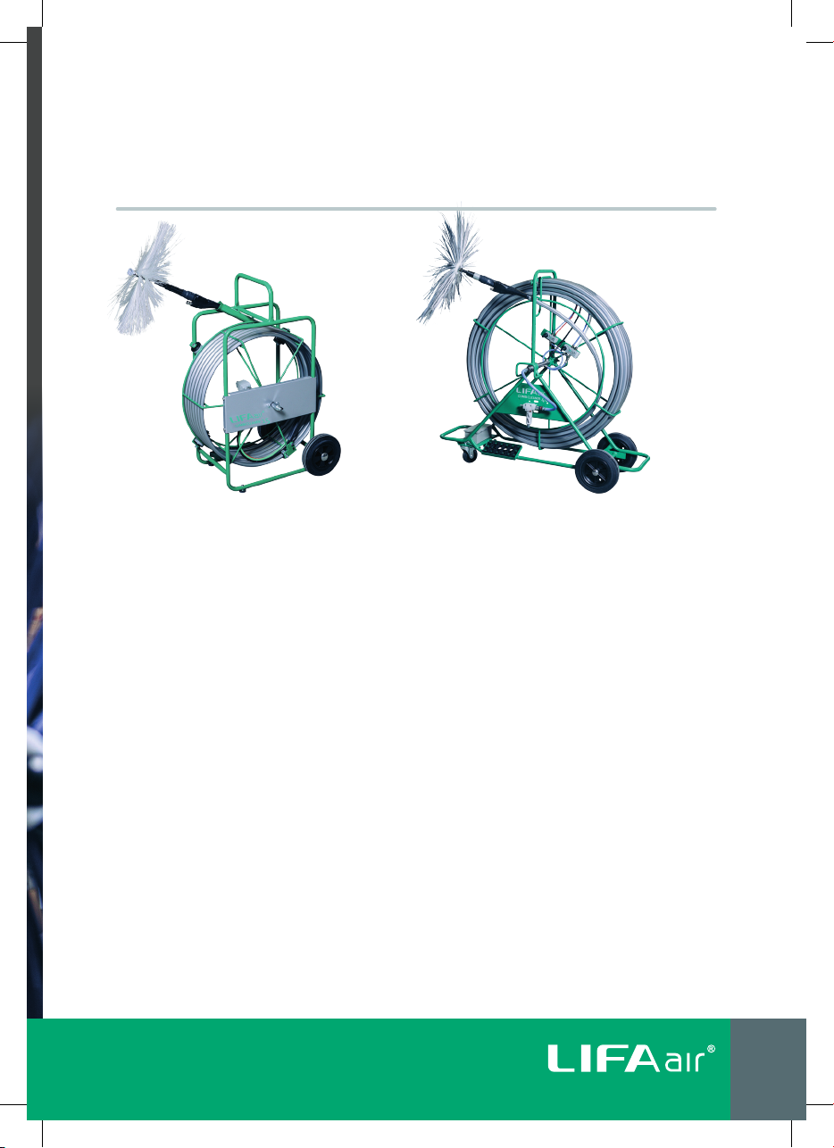
GREASE DUCTS: LIFA Combi Cleaner brushing machines may be used for grease duct
cleaning. Please ask us more about our grease removal concept!
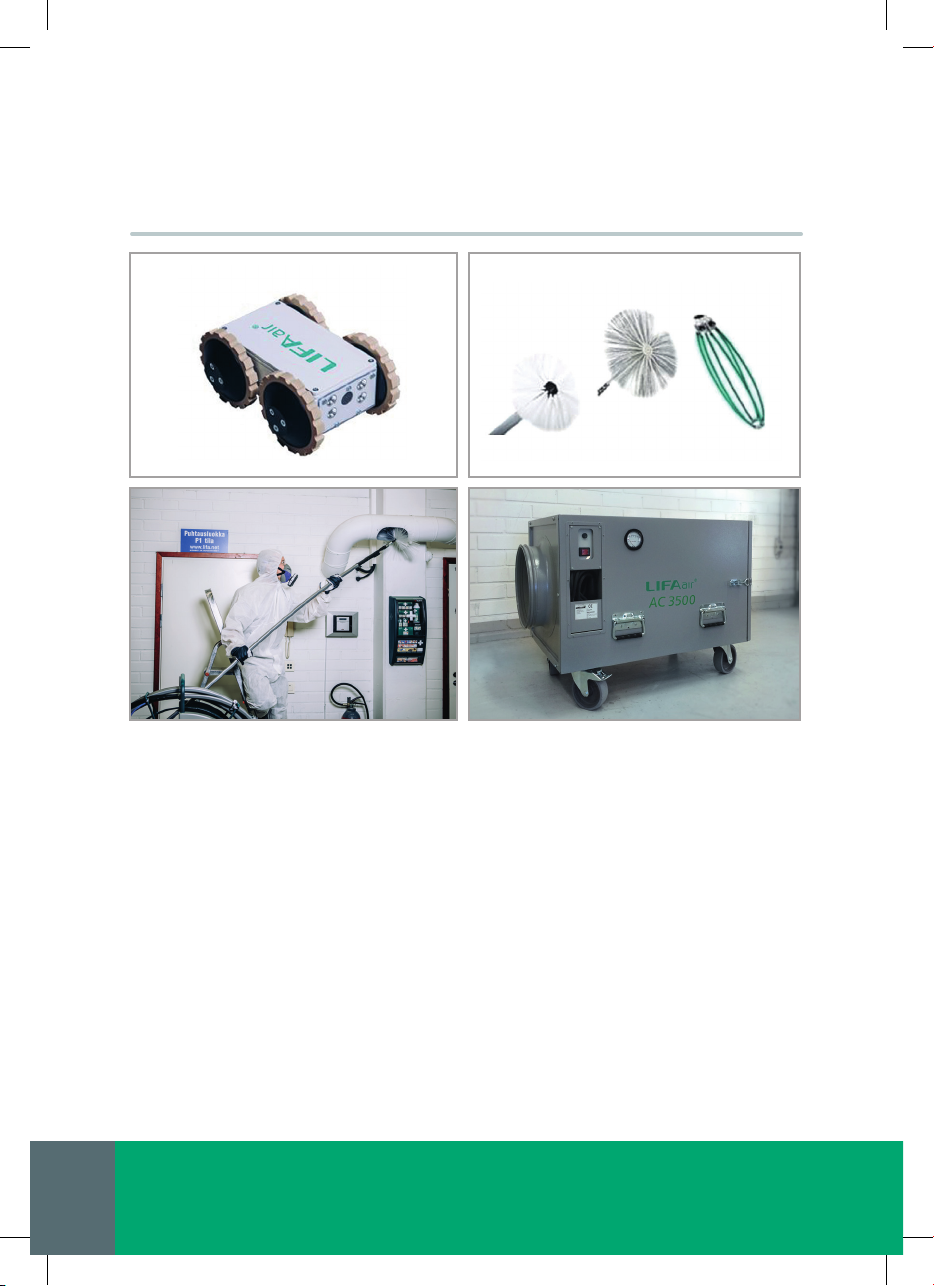
cleaned.Nylon grease / Tynex brushes
are meant mainly for grease exhaust
duct cleaning.
• Ifthepurposeistospraycoatingor
disinfectantintotheductatsametime,
placeacompressedairorlow-pressure
airsprayerintothemachinedepending
onthepurposeofuse.Choosea
correctnozzle(checktheaccessorylist).
• Makesurethattheworkingareais
clearedandtherearenoextrapeople.
• Ensurethatalltheemployees
performingtheworkhaveadequate
protective equipment.
• Makesurethatthereisenoughlow
pressureintheductworkandthatLIFA
HepaCleanorLIFAAirCleannegative
pressureunit(NPU)isinstalledcorrectly.
Thebrushedoffdebrisisremovedby
suckingittothenegativepressureunit.
• Connectthecompressedairinto
themachine.Beforeconnecting
thecompressedair,checkthatthe
compressedairtabisoffandairvalves
areinthecentreposition.
• Placethebrushinside the ventilation
ductthatisgoingtobecleaned.
• Whentheoperator,whoisfeedingthe
shaftintotheductgivesapermission
tostartrotation,theotherworkerat
brushingmachineturnstheoperation
valve.Thisisdonebyopeningthe
compressedairtabrstandthenthe
compressedairvalvecanbeturned
intotheotherside,dependingon
therotatingdirection.Thevalveofthe
compressedairtabadjuststherotating
speed.Inthefullyopenpositionthe
rotatingspeedofthebrushisthe
fastestpossible.
• Whentheshaftisbeingfedtotheduct
sharp angles and screws etc. that can
damage the shaft must be beware of.
• Adjusttherotatingspeedofthe
brush.Notethatwhencleaning“soft”
internallyinsulatedductstherotating
speedshouldbemuchlowerthanin
normalducts.Toohighrotationspeed
maydamagetheventilationduct.
• Thebrushcanberotatedtoclockwise
andcounterclockwise.Useboth
rotatingdirectionstoachievethebest
cleaningresult.Inrectangularducts,it
mayberequiredtocleanonesiderst
(withrotatingthebrushinonedirection
only)andafterthatanotherside.
• Feedtheshaftevenlyintotheduct
withoutexcessiveforce.Theuseof
excessiveforcemayharmtheduct,
machineorbrushandinuenceonthe
cleaningresult.Alwaysinserttheshaft
gentlyandsmoothlyintotheductwork,
topreventthebrushfrom‘jumping’and
leavinguncleanspotsintotheduct.
• Itisalsoadvisedtousespecially
designedcenteringdeviceand/orshaft
holderbyLIFAinbigductsand/orwhen
fullrotationspeedisbeingused.
9

Service and Maintanance
Beforeanymaintenancecompressorneedstobedisconnectedandallpressurefrom
machinereleased.
Thefollowingmaintenanceandupkeepworkmustbedoneinregularbasisdependingon
thepurposeofwhichthemachineisbeingused.Thisenablesatrouble-freeuse.
General Cleanliness: Keepthemachineasfreefromdirtanddustaspossible.Dirtand
greasemaycausedefectsinthecompressedairvalves.Themachinecanbewashedwith
milddetergentandwater.
Maintenance
Lubricating Combi Cleaner 15 motor
Remember to lubricate the pneumatic
motor at the end of each working day by
spraying few seconds of light motor oil*
to the air inlet connector (not to the water
separator) when the operation valve and
air inlet valve are open (Image 1). Tilt the
device slightly so that the oil goes deeper
into the tube.
Connect compressed air to the connector
and run motor few seconds to one direc-
tion only (Image 2).
Repeat the oil spraying and connect
compressed air to the air connector and
run the motor few minutes to the same
direction as rst time until the oil reaches
the motor (motor starts to run faster, and
some oil mist can be seen coming out from
the motors air outlet).
Now the motor is lubricated and ready for
next use.
Image 1
Spraying light motor oil* to the air hose connector
when the operation valve and air inlet valve are open.
*WürthRostOffPlus,WD40,CRC5-56oranalog
Image 2
Connect compressed air to the connector and
run the motor few seconds.
10
LIFA Special Cleaner 20 / 25 Multi

Cleaning shaft: Thecleaningshaftmust
becleanedeverytimeafteruse.Thedirt
andgreasethathascollectedtotheplastic
surfacecanberemovedwithamildgrease
removaldetergentthatismeantforplastic
surfaces.Somelubricant(syntheticVaseline,
lubricatingoiletc.)mustbeputbetweentheturnbuckleandtheouterbearinginthebrush
adapterregularly.
Liquid hose:Afteruse,thehoseshouldberinsedwithcleanwater,sotheywillnotget
blockedandtherewillbenoresiduesofolddetergents.Corrosivedetergentsandsolvent
substancesmaydamagetheinsideofthehose.Afterrinsingthehoseshouldberunclean
withcompressedair.
Liquid nozzles: Afteruse,thenozzlesandthehosesshouldberinsedwithwater,sotheywill
notgetblockedandtherewillbenoresiduesofolddetergents.Corrosivedetergentsand
solventsubstancesmaydamagetheinsideofthehose.Afterrinsingthehoseshouldberun
cleanwithcompressedair.
Lubricating Combi Cleaner 40 motor
Remember to lubricate the pneumatic
motor at the end of each working day by
spraying few seconds of light motor oil*
to the air inlet connector (not to the water
separator) when the operation valve and
air inlet valve are open (Image 1). Tilt the
device slightly so that the oil goes deeper
into the tube.
Connect compressed air to the connector
and run motor few seconds to one direc-
tion only (Image 2).
Repeat the oil spraying and connect
compressed air to the air connector and
run the motor few minutes to the same
direction as rst time until the oil reaches
the motor (motor starts to run faster, and
some oil mist can be seen coming out from
the motors air outlet).
Now the motor is lubricated and ready for
next use.
NOTE! Possible repairs must be carried out by the manufacturer or a servicer authorized
by Lifa Air Oy Ltd. Third party repairs will void the warranty.
Image 1
1. Open air inlet valve and operation valve.
2. Spray light motor oil* to the air hose connector.
*WürthRostOffPlus,WD40,CRC5-56oranalog
Image 2
Connect compressed air to the connector and
run the motor few seconds.
11

Troubleshooting
Possibleproblemsituationsandsolutionsarepresentedbelow.Ifyouarenotsureonhowto
handleproblemsituationsdonothesitatetocontactus.Ourexpertsarepleasedtoadvice
andhelpyouinawaywecangetthedesiredoutcometogether.
1. Thecompressedairhasbeenconnectedintothemachineandtheconnector
valveisopen,butthebrushstilldoesn’trotate.
a) Makesurethatthecompressedairvalveisn’tstuck,anditisinopen
position.
b) Makesurethatthefeedofthecompressedairorthecleaningshafthoses
aren’tstuck.
2. Thecleaningbrushdoesn’tstarttorotateeventhoughthecompressedairis
comingtothemotor.
a) Makesurethatanyofthecompressedairjointsaren’tleaking.Ifthejoints
areleakingthepressuremaybesolowthatthemotordoesnotrotate.
b) Switchthecompressedairofffromthemachineandmakesurethatthe
motorisn’tstuckbyrotatingitwithe.g.awrenchfromthebrushadapter.
Themotorshouldrotateconsiderablyfreely.Therefore,donotuse
excessiveforce.Ifthemotordoesnotrotatefreely,dotheproceduresthat
areinstructedinthemaintenance-airmotor.
3. Whenloaded,thebrushdoesnotrotate.
a)Checkthesizeofthebrushincomparisontotheduct.Toobigbrushmay
causethemotortostop(ifyoudon’thaveenoughairpower).
b)Makesurethatthemainvalveisopenentirely.
c) Makesurethatthepressureinthecompressedaircompressorisadjusted
highenough(about7bar).
4. Nothingiscomingoutfromtheliquid/compressedairnozzleseventhoughthe
liquid/compressedairisattachedtothemachine.
a) Makesurethatthevalveisinanopen-position.
b)Ifyouaresprayingliquidsmakesurethatthereisenoughpressureinthe
low-pressuresprayer(2-5bar)
c) Makesurethatthenozzlesaren’tstuck.
d) Checkthatthejointsareinrightplaces.
e) Ifthereareanyolddetergentsetc.leftinthehose,theymaycausethe
hosetoclog.Thehosecanbetriedtoopenbysprayingwarmwateror
milddetergentsolutionintothehose.
12
LIFA Special Cleaner 20 / 25 Multi

Technical Data
LIFA Combi Cleaner 15 and 40 brushing machines
Large variety of nozzles and accessories available for spraying disinfectants to ducts and sub oor
spaces.
CE-plate is situated behind the protective switch for motor above the motor. Plugging in,
maintenance and spare part supply must be done in accordance with the information given in this plate.
LIFA Combi Cleaner 15 LIFA Combi Cleaner 40
Operating power Compressed air Compressed air
Operating voltage and
frequency
- -
Motor 0.11 kW (0.15 hp) 0.4 kW (0.6 hp)
Fuse - -
Max torque 3 Nm (2.2 ft•lb) 6,5 Nm (4.8 ft•lb)
Brush connection M12 M12
Duct size recommendation 160–600 mm (6.3–23.6") 400–1200 mm (15.7–47.2")
Brush rotation speed Continuous adjustment
max. 1000 rpm
Continuous adjustment,
max. 670 rpm
Rotation controls Manual / Air valve Manual / Air valve
Nozzle connection Quick coupling Quick coupling
Air volume consumption 340 l/min (12 CFM), 7 bar 450 l/min (14 CFM), 7 bar
Measurements:
Height:
Length
Width
910 mm (35.8”)
640 mm (25.2”)
480 mm (18.9”)
1290 mm (50.8”)
1100 mm (43.3”)
570 mm (22.4”)
Weight: 17 kg (37 lbs) 45 kg (99 lbs)
Cleaning shaft 15 m (49.2 ft.) 40 m (131.2 ft.)
Accessories Y-gear, 3-brush-gear, mechanical
centering device, spray bottle,
nozzles
Y-gear, 3-brush-gear, pneumatic
centering device, spray bottle,
nozzles
13

Spare parts and accessories
COMBINATION BRUSHES WITH NYLON CENTER AND DISK
SOFT BRUSHES WITH NYLON CENTER
AGGRESSIVE NYLON BRUSHES (grease brush) WITH NYLON CENTER
CC15 CC40
6420281010507 200/400 mm (8/16 inch) x
6420281010514 300/500 mm (12/20 inch) x
6420281012624 400/600 mm (16/24 inch) x x
6420281010736 500/700 mm (20/28 inch) x x
6420281013027 600/800 mm (24/32 inch) x x
6420281010743 700/900 mm (28/35 inch) x
6420281021848 800/1000 mm (32/39 inch) x
6420281012334 1000/1200 mm (39/47 inch) x
6420281021916 1300 /1500 mm (51/59 inch) x
CC15 CC40
6420281010583 400 mm (16 inch) x
6420281010590 500 mm (20 inch) x x
6420281010606 600 mm (24 inch) x x
6420281010613 700 mm (28 inch) x x
6420281010620 800 mm (32 inch) x x
6420281010637 900 mm (35 inch) x
6420281010644 1000 mm (39 inch) x
CC15 CC40
6420281010750 200 mm (8 inch) x
6420281010767 300 mm (12 inch) x
6420281010774 400 mm (16 inch) x x
6420281010781 500 mm (20 inch) x x
6420281010798 600 mm (24 inch) x x
14
LIFA Special Cleaner 20 / 25 Multi

OTHER ACCESSORIES(WITH SPECIAL ADAPTER)
6420281020865 Mechanical centering device for
LIFA Combi Cleaner 15
6420281024559 Pneumatic centering device for
LIFA Combi Cleaner 40
7720281060038 Low pressure spraying unit 5l,
stainless steel
6420281012006 Foam Nozzle
ABRASIVE BRUSHES WITH NYLON CENTER, TYNEX BRISTLE
GREASE AND HEAVY-DUTY BRUSH, CHOPPER (WITH SPECIAL ADAPTER)
CC15 CC40
6420281023439 200/400 mm (8/16 inch) x
6420281021213 400/600 mm (16/24 inch) x x
6420281023484 600/800 mm (24/32 inch) x x
6420281023507 800/1000 mm (32/39 inch) x
6420281024290 1000/1200 mm (29/47 inch) x
6420281024306 1300/1500 mm (51/59 inch) x
CC15 CC40
6420281020216 Grease Duct chopper, Large
800 mm (32 inch) adjustable
for ducts 500–1100 mm
(20-43 inch)
x
6420281020209 Grease Duct chopper, Small
350 mm (14 inch) adjustable
for ducts 250–550 mm
(10–22 inch)
x x
15

Warranty
Thewarrantyperiodisone(1)year
startingfromthedateofpurchaseand
isvalidaccordingtotheregulartermsof
delivery,providedthattheseoperational
andmaintenanceinstructionshavebeen
carefullyfollowed.Usinganythingother
thanoriginalLIFAaccessories(brushes,
ltersetc.)intheequipmentwillvoid
thewarranty.
Repairisfreeofchargewithinthe
warrantyperiod(proofofpurchase/
receiptmustbepresented)underthe
followingconditions:
• Thedefectiscausedbydefectsin
materialsordefectivecomponents.
• Defectscausedbynormalwear
andtear,misuseorinsufcient
maintenanceareNOTcoveredby
thewarranty.
• Themachinehasbeendeliveredto
therstcompulsorymaintenance
checkwithin6monthsand/or100
hoursofuse.
• Anymaintenanceandrepairsmustbe
carriedoutbythemanufacturerorby
anauthorizedrepresentativeofthe
manufacturer.Manufacturerdoesnot
takeresponsibilityformaintenance
carriedoutbyathirdparty.
• Awrittenreclamationformhastobe
lledoutandsentwithdescriptive
photostothemanufacturer.
Theapplianceshallbedelivered
totheauthorizedLifaAirOyLtd
representativefromwhomthebuyer
hasboughtthemachinefromORwhen
agreedmutuallyinwritingbeforehand
tothefactorypostagepaidto:
Lifa Air Oy Ltd
Vellamonkatu 30 B
FI-00550 Helsinki
FINLAND
Tel. +358 9 3948 58
Email: sales@lifa.net
Pleasenotethatthemachinemustbe
cleaned of hazardous materials before
sendingittothemanufacturerora
servicerauthorizedbymanufacturerfor
maintenance.Incasethemachinehas
notbeencleanedappropriately,
LifaAirOyLtdwillchargethecustomer
forthecleaningofthemachine.
LifaAirOyLtdreservestherightto
introducechangeswithoutafurther
notice.
16
LIFA Special Cleaner 20 / 25 Multi

Recycling
ThemachinecanalwaysbereturnedtotheLifaAirauthorized
representativefromwhichthebuyerhasboughtthemachinefrom,or
totheaddressabovepostagepaidincasethereisnorecyclingfacility
wheretheownerlives.
• Metalparts(frame,reel,motor)canberecycledasmetalscrap.
• Electricalparts(frequencyconverter,mainswitch)shouldbereturned
toanauthorizedrecyclingdepot.
• Otherpartscanberecycledasmixednormalwaste.
17

Declaration of Conformity
LIFA Air Product Family
Manufacturer’s name: LifaAirOyLtd
Manufacturer’s address: Vellamonkatu30B,
FI-00550Helsinki,Finland
Manufacturer’s telephone: +3589394858
Manufacturer’s website: www.lifa.net,www.lifa-air.com
Model: LIFA Combi Cleaner 15
LIFA Combi Cleaner 40
LifaAirOyLtdisISO9001andISO14001Certied.
Lifa Air Oy Ltd, hereby states, with sole responsibility, that the machine models
covered by this announcement comply with the requirements of the following
EC directives and standards:
• EULowVoltageDirectiveLVD2014/35/EY
• EUElectromagneticCompatibilityDirectiveEMC2014/30/EY
• EUDirectiveoftherestrictionoftheuseofcertainhazardoussubstancesin
electricalandelectronicequipmentRoHS2011/65/EC
• ENISO12100:2010Safetyofmachinery
• EN60204-1:2007Safetyofmachinery.Electricalequipmentofmachines.
GeneralRequirements.
TheproductfullsrequirementsforCE-marking.
Lifa Air Oy Ltd 10.01.2018
Johan Brandt, CEO
18
LIFA Special Cleaner 20 / 25 Multi

LIFA Air Product Family
SC 20 SC 25 Multi
Hydmaster 40
CC 15 CC 40 AirJet
Combi 20
DC Robo
Operating
power
Electricity Electricity Hydraulics Compressed
Air
Compressed
Air
Compressed
Air
Compressed
air (brush)
+ electricity
(driving)
Operating
voltage
and
frequency
240 VAC (or
110-120 VAC),
1~, 50/60 Hz
240 VAC (or
110-120 VAC),
1~, 50/60 Hz
240 VAC (or
110-120 VAC),
1~, 50/60 Hz
-- -- -- 12 VDC
Motor
0,37 kW
(0.5 hp)
0,75 kW
(1.0 hp)
1,1 kW
(1.5 hp)
0,11 kW
(0.15 hp)
0,4 kW
(0.6 hp)
-- 0,11 kW
(0,15 hp)
Fuse
10 A 10 A 16 A -- -- -- 5 A
Max torque
5 Nm
(3.7 ft•lb)
5 Nm
(3.7 ft•lb)
10 Nm
(7.4 ft•lb)
3 Nm
(2.2 ft•lb)
6,5 Nm
(4.8 ft•lb)
-- 3 Nm
(2.2 ft•lb)
Brush
connection
M12 M12 M12 M12 M12 - M12
Duct size
recom-
mendation
100–400 mm
(3,9–15,7")
250–800 mm
(9,8–31,5")
400–1200 mm
(15,7–47,2")
160–600 mm
(6,3–23,6")
400–1200 mm
(15,7–47,2")
-- 200–700 mm
(7,9–23,6")
Brush
rotation
speed
Continuous
adjustment,
225–580 rpm
Continuous
adjustment,
225–580 rpm
Continuous
adjustment,
225–880 rpm
Continuous
adjustment
max. 1000 rpm
Continuous
adjustment,
max.670 rpm
-- Continuous
adjustment,
max.1000 rpm
Rotation
controls
Foot pedal,
remote
hand control
(accessory)
Foot pedal,
remote
hand control
(accessory)
Foot pedal,
remote
hand control
(accessory)
Manual /
Air valve
Manual /
Air valve
-- Manual /
Air valve
Nozzle
connection
- Quick
coupling
- Quick
coupling
Quick
coupling
Quick
coupling
Quick
coupling
Air volume
consump-
tion
- Nozzle type
dependant
- 340 l/min
(12 CFM),
7 bar
400 l/min
(14 CFM),
7 bar
100–600
l/min
(3.5–21
CFM
),
7 bar
340 l/min
(12 CFM),
7 bar
Measure-
ments
[mm]
H910 (35.8")
L640 (25.2”)
W480 (18.9”)
H1290 (50.8")
L1100 (43.3”)
W570 (22.4”)
H1290 (50.8")
L1100 (43.3”)
W570 (22.4”)
H910 (35.8")
L640 (25.2”)
W480 (18.9”)
H1290 (50.8")
L1100 (43.3”)
W570 (22.4”)
H910 (35.8")
L640 (25.2”)
W480 (18.9”)
H190 (7.5")
L410 (16.1”)
W280 (11”)
Weight
38 kg
(84 lbs)
71 kg
(157 lbs)
93 kg
(205 lbs)
17 kg
(37 lbs)
45 kg
(99 lbs)
15 kg
(33 lbs)
8 kg
(18 lbs)
Cleaning
shaft
20 m
(65.6 ft.)
25 m
(82 ft.)
40 m
(131 ft.)
15 m
(49.2 ft.)
40 m
(131 ft.)
20 m
(65.6 ft.)
25 m (82 ft.)
(driving cable)
Accessories
Mechanical
centering
device, hand
controller
Y-gear,
mechanical
centering
device, hand
controller,
spray bottle,
nozzles
Y-gear,
3-brush-gear,
mechanical
centering
device, hand
controller
Y-gear,
3-brush-gear,
mechanical
centering
device, spray
bottle, nozzles
Y-gear,
3-brush-gear,
pneumatic
centering
device, hand
controller
Mechanical
centering
device,
spray bottle,
nozzles
Y-gear,
3-brush-gear,
spray bottle,
nozzles
19

Lifa Air Oy Ltd
Vellamonkatu 30 B, 00550 Helsinki, Finland
+358 9 3948 58 | sales@lifa.net | www.lifa.net | www.lifa-air.com
These instructions should always be available for the personnel operating the machine.
Please read these instructions carefully before operating the machine.
Following these instructions in detail ensures many years of trouble-free use.
This manual suits for next models
2
Table of contents
Other Lifa Air Ultrasonic Jewelry Cleaner manuals