Lifebreath 350DCS Specification sheet

69-350DCS
072020
New Auto Dehumidistat Function
prevents unwanted use of the dehumidistat when outdoor temperatures exceed 15°C (59°F).
INSTALLER: Leave this manual for the homeowner
Operation and Installation Manual
Commercial Double Core
Heat Recovery System
Model
350DCS
Installation and wiring to be in accordance
with CEC, NEC and local electrical codes.
Important: Read and save these instructions.

Specifications - Model 350DCS.........................................3
Controlling Your HRV ......................................................5
Glossary
Included Lifebreath Digital Control ...................................7
How the Dehumidistat Works ........................................10
Optional Wireless Timers ..........................................14-16
Location of the HRV for Mounting ..................................18
The Ductwork System
Outside Weatherhoods .................................................19
Stale Air Return System
Fresh Air Supply System
Adjustable Grilles..........................................................20
The Integrated HVAC System ........................................21
Drain Connection .........................................................22
Installation of the Main Control..................................12-13
Interlocking the HRV to an Airhandler/Furnace Blower ....17
Dry Contacts
Balancing the HRV ........................................................23
Service and Maintenance ..........................................24-25
Wiring Diagram ............................................................26
2
Table of Contents
LEAVE WITH UNIT
TO BE COMPLETED BY CONTRACTOR AFTER INSTALLATION
Installing Contractor _________________________________________Telephone / Contact _____________________
Serial Number______________________________________________Installation Date ________________________
Model _________________________________________________________________________________________
CAUTION
Before installation, careful consideration
must be given to how this system will
operate if connected to any other piece of
mechanical equipment, i.e. a forced air
furnace or air handler, operating at a
higher static. After installation, the
compatibility of the two pieces of equipment
must be confirmed, by measuring the air
flows of the HRV, by using the
balancing procedure found in this
manual. NEVER install a ventilator in a
situation where its normal operation, lack
of operation or partial failure may result
in the backdrafting or improper functioning
of vented combustion equipment.
Do not apply electrical power to the
unit until installation has been fully
completed (including low voltage control
wiring).
NOTE
IMPORTANT -
PLEASE READ THIS MANUAL
BEFORE INSTALLING UNIT.
Due to ongoing research and product
development, specifications, rating and
dimensions are subject to change without
notice. Refer to www.LIFEBREATH.com for
the latest product information.
Selecting the Mode of Operation That's Right For You .......6
Optional Lifebreath Ventilation Controls ......................8-10
Optional Lifebreath Dehumidistat ...................................11
Optional 20/40/60 Minute Timer
Optional Mechanical Timer
Warranty .....................................................................27

3
49"
(1245 mm)
8"
(200 mm)
FRONT VIEW
18 3/4"
(475 mm)
28 1/4"
(717 mm)
14"
(356 mm)
5 7/8"
(150 mm)
1 1/4"
(32 mm
)
INTERIOR DUCT
CONNECTION SIDE
18 3/4"
(475 mm)
8"
(200 mm)
28 1/4"
(717 mm)
14"
(356 mm)
5 7/8"
(150 mm)
1 3/8"
(35 mm)
EXTERIOR DUCT
CONNECTION
SIDE
MOUNTING POINTS
EXHAUST AIR
TO OUTSIDE
EXHAUST AIR
FROM BUILDING
SUPPLY AIR
TO BUILDING
SUPPLY AIR
FROM OUTSIDE
NOTE:
Service
clearance
is
30
in.
(760
mm)
DRAIN CONNECTION
DEFROST
CORES
Two modular (two section) aluminum HRV cores arranged for high efficiency cross-flow ventilation.
MOTORS
Two PSC, 5 speed double shafted, 120 VAC, 3.15 A motors. (6.3 A total on high speed) with 1/10
hp at 1625 RPM. Total of 610 watts on High speed. MCA: 7.9 MOP:10
BLOWERS
Centrifugal-type rated at 530 cfm (250 L/s) free air delivery. Each air stream has two centrifugal
blowers driven by two PSC motors.
FILTERS
Washable air filters in exhaust and supply air streams.
DEFROST
Supply bypass damper routes indoor air to defrost cores.
WEIGHT 160 lbs. (70 kg) SHIPPING WEIGHT 240 lbs. (110 kg)
CONNECTION DUCT SIZES
Four 14”x 8” ( 356 mm x 200 mm)
MOUNTING
Unit to be set on support brackets hung by threaded rod-type apparatus (brackets and rods not
included).
CASE
Twenty gauge pre-painted galvanized steel (G60) for superior corrosion resistance. Insulated with
foil faced insulation duct liner where required to prevent exterior condensation. One drain
connection 1/2" (12 mm) OD.
ELECTRONICS
Integrated microprocessor circuit board. Built-in interlock contacts.
Date: ___________________________________________
Tag: _____________________Qty:___________________
Project: _________________________________________
Engineer: _______________________________________
Contractor: ______________________________________
Supplier: ________________________________________
Quote#: _________________________________________
Submitted by: ____________________________________
PERFORMANCE
Net
supply
airflow
in
cfm
(L/s)
against
external
static
pressure
E.S.P cfm L/s
@ 0.1” (25 Pa) 450 (212)
@ 0.2” (50 Pa) 426 (201)
@ 0.3” (75 Pa) 400 (189)
@ 0.4” (100 Pa) 371 (175)
@ 0.5” (125 Pa) 337 (159)
@ 0.6” (150 Pa) 304 (143)
@ 0.7” (175 Pa) 269 (127)
@ 0.8” (200 Pa) 158 (75)
@ 0.9” (225 Pa) 107 (50)
VAC @ 60HZ 120
WATTS / Low speed 187
WATTS / High speed 610
Amp rating 6.3
AIRFLOWS (Each Air Stream)
250
200
150
100
50
0.1 0.2
100%
90%
80%
300
(143)
400
(190)
500
(235)
600
(282)
AIRFLOW IN CFM (L/s)
NOTE: Exhaust Relative Humidity (RH) at 40%
EFFECTIVENESS
200
(94)
300
5
1
2
3
4
*3 - Medium Speed
*1 - Low speed
*5
*4
-High Speed
-Medium High Speed
*2 - Medium Low speed
0
350
400
450
500
0.3 0.4 0.5 0.6 0.7
EXTERNAL STATIC PRESSURE (inches W.C.)
TEMPERATURE EFFECTIVENESS
0.8 0.9
Specifications 350DCS
AIRFLOW CFM
DIMENSIONS inches (mm)
All units conform to
CSA and UL
standards
NOTE: All
specifications are
subject to change
without notice.
WARRANTY
Units carry a 15 year warranty
on the HRV core and a 2 year
replacement parts warranty.
99-BC03 Lifebreath Ventilation Control
•
•
•
Continuous Low fan speed Humidity
control through adjustable
Dehumidistat
3 modes of operation: Ventilation,
Recirculation, 20/40
•
Compatible with 99-DET02 Wireless
Timers
•
3 wire connection
CONTROL OPTIONS
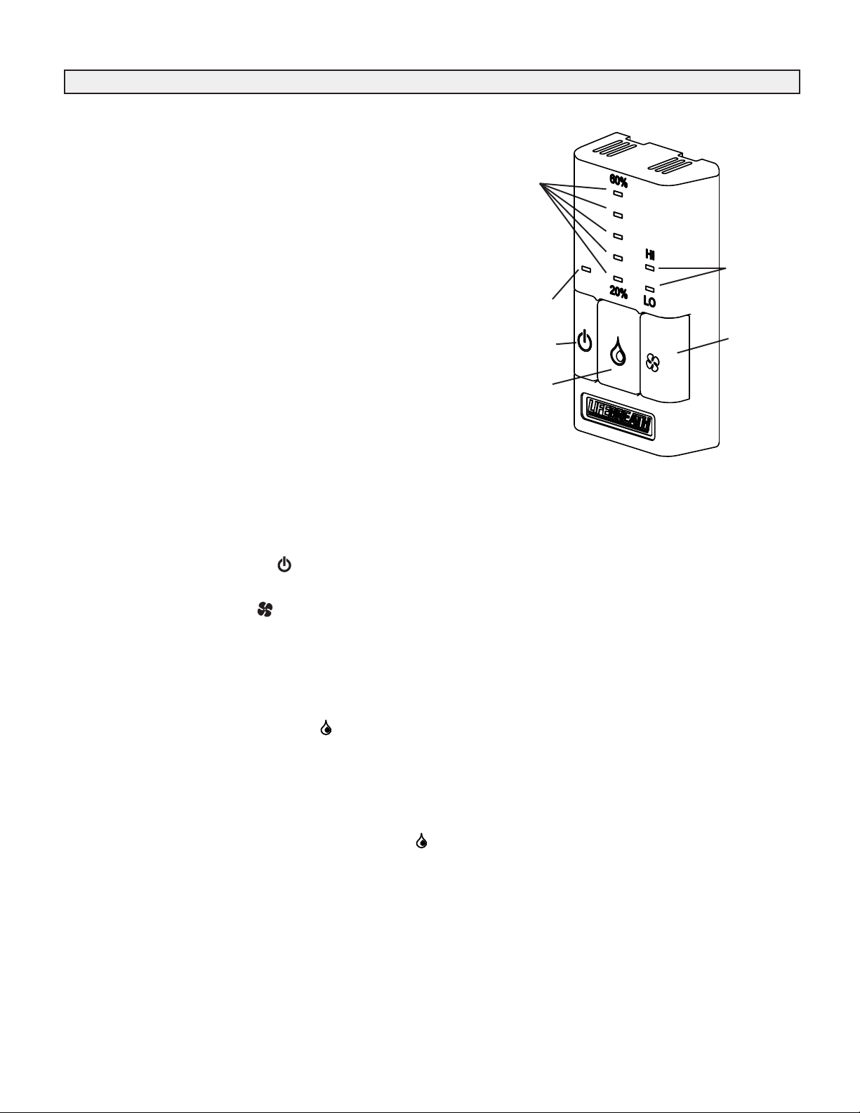
99-DXPL02 Lifebreath Digital Control
(Included)
•
•
5 speed operation on each mode
Humidity control through adjustable
Dehumidistat
•
5 user selectable operational modes: Continuous
Ventilation, Continuous Recirculation, 20 ON/40
OFF, 10 ON/50 OFF, 20 ON/40 Recirculation
•
20/40/60 min. High speed override
button
•
Compatible with 99-DET02 Wireless
Timers
•
3 wire connection
99-BC02 Lifebreath Ventilation Control
•
2 speed fan setting (Low/High)
•
Humidity control through adjustable
Dehumidistat
•
Compatible with 99-DET02 Wireless
Timers
•
3 wire connection
99-BC04 Lifebreath Ventilation Control
•
2 speed fan setting (Low/High)
•
2 modes of operation: Ventilation, 20/40
•
Compatible with 99-DET02 Wireless
Timers
•
3 wire connection
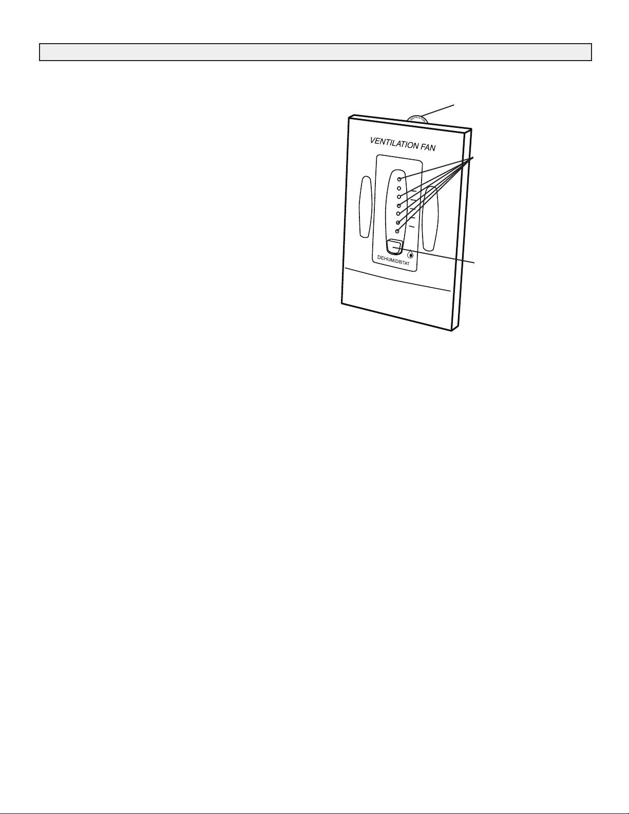
99-DH01 Lifebreath Dehumidistat
•
Humidity control through adjustable
Dehumidistat
•
3 wire connection
TIMER OPTIONS
99-DET01 Lifebreath 20/40/60 Minute Timer - Initiates High speed Ventilation for 20, 40 or 60 minutes. 3 wire connection.
99-DET02 Lifebreath WIRELESS 20/40/60 Minute Timer - Initiates High speed Ventilation for 20, 40 or 60 minutes.
Wirelessly connects to main control for ease of installation. 40' approximate range.
99-RX02 Lifebreath WIRELESS Repeater - Used to extend range of 99-DET02 Wireless Timers. Plugs into 120V power
outlet. Wirelessly connects to main control and 99-DET02. Install at halfway point between timer and main wall control
if timer is out of range.

5
Today's modern, tight buildings require fresh outdoor air to
maintain a healthy indoor air environment. The amount of
ventilation you require in the building will depend upon:
•The number of occupants and their activity levels
•The way the building was built
•Your personal preferences for fresh air
The HRV introduces fresh air to the building while recovering
energy from the air it exhausts. Specifically, an HRV that is
properly installed, operated and maintained will:
•exhaust stale, contaminated air
•recover the majority of the energy from the
exhausted stale air
•use the recovered energy to preheat or precool outside
air that is drawn into the building
•distribute the fresh air throughout the building
HOW MUCH VENTILATION DO I NEED?
During seasons when your windows and doors are closed
(winter, and summer if air conditioned), the HRV should be
set to operate continuously on low speed with the option of
going to high speed as the need arises. For example, if you
are entertaining and there is a large number of people
present, the unit should be switched temporarily to high
speed.
You may wish to use an intermittent operational mode if
the building is unoccupied (20 minutes ON / 40 minutes
OFF or 10 minutes ON / 50 minutes OFF for even less
ventilation).
Controlling Your HRV
Glossary
DEFROST MODE - to ensure reliable operation during
cold weather, the HRV will automatically cycle through its
defrost mode as needed.
DEHUMIDISTAT - a control device that senses the
amount of moisture in the air and activates high speed
ventilation when the air moisture level in the home
exceeds the set point.
RECIRCULATION - Recirculates existing household air
without introducing fresh air.
RESET - whenever resetting of the HRV is required,
disconnect power for 30 seconds. The Self Test will occur
when the HRV is re reconnected.
SELF TEST - each time the HRV is powered/energized
the self test function will automatically initiate. During the
self test the HRV will cycle through all the speeds
available (1-5), test the damper motor operation and will
default back to the previous operational mode and speed
selection. Total self test duration is approximately 90
seconds.
STANDBY MODE - the HRV is powered/energized and
waiting for fan operation to be initiated. For example, the
HRV is set a Continuous Ventilation Operational Mode at
Speed 0.
THERMISTOR - the HRV's temperature sensor which
measures electrical resistance in a known manner, as
outdoor temperatures fluctuate.
VENTIALTION - Operational mode that introduces fresh
outdoor air to the home or building.

6
The modes of operation and speeds are used to adjust your indoor ventilation rate. Experiment with the ventilation levels in
your home to evaluate the ideal amount of ventilation to suit your home and personal preferences. Operational modes
available to you will depend on the main control that is installed. Some features and modes may be unavailable to you.
Selecting the Mode of Operation that’s Right for You
GOOD Standby (fan speed set to 0 or
OFF)
Allows unit to run on demand from remote controls such as
a Timer or Dehumidistat.
BETTER Intermittent low speed operation
20 ON/40 OFF
Provides 20 minutes air exchange and 40 minutes off.
BEST Continuous LOW fan speed
operation
Ensures continuous air exchange within the building. Air is
always fresh and healthy.
Recirculation
Recirculates existing household air without introducing fresh air. Recirculation modes (II and V) are not applicable if your HRV
is connected to a forced air system, since your forced air system already circulates the household air. Recirculation modes are
unavailable on some models.
I. Continuous Ventilation
This mode of operation provides continuous ventilation within the home. You may, for example, select Continuous
Ventilation at low speed for normal operation and increase to high speed during increased activity levels, such as cooking
and showering, etc.
II.20 Minutes On, 40 Minutes Recirculation 20/hr 40/hr
This mode ventilates for 20 minutes and recirculates the household air every 40 minutes each hour. This mode is not
applicable if your HRV is connected to a forced air system.
III. 20 Minutes On, 40 Minutes Standby 20/hr 40/hr
This mode of operation provides 20 minutes of ventilation each hour. You can use this ventilation mode at low speed for low
household activity levels or when the home is unoccupied.
IV. 10 Minutes On, 50 Minutes Standby 10/hr 50/hr
This mode of operation provides 10 minutes of ventilation each hour. You can use this ventilation mode at low speed for low
household activity levels or when the home is unoccupied. This mode is useful when 20/40 mode is providing too much
ventilation.
V. Continuous Recirculation
or
This mode continuously recirculates your household air (no ventilation). This mode is not applicable if your HRV is connected
to a forced air system.
VI. Continuous Low Fan Speed LO
This mode will operate the fan in low speed continuously at the selected operating mode (Ventilation or Recirculation).
VII. Continuous High Fan Speed HI
This mode will operate the fan in high speed continuously at the selected operating mode
(Ventilation or Recirculation). This mode is useful when occupancy in the home or activity is high for an extended period of
time.

Included Lifebreath Digital Control - Part #99-DXPL02
Key Features:
7
Instruction Card
Mode
Button Dehumidistat
Button RESET Button
20/40/60 High
Speed Button
Digital Control Operating Instructions (DXPL02):
Turning on the Control
Press and release the ON/OFF button . The light above will illuminate.
Setting the Ventilation Speed
Press and release the Fan button to select one of the 5 fan speeds. The fan speed will be displayed on the screen beside the
Fan symbol . Standby mode (Fan OFF) is indicated as speed 0. The fan will turn ON if required by a remote Timer (if installed).
20/40/60 High Speed Button
Press and release the 20/40/60 High Speed button to temporarily initiate HIGH Fan speed for 20, 40 or 60 minutes. Press
once for 20 minutes, twice for 40 minutes, 3 times for 60 minutes and 4 times to disable. The will appear on the screen and
the corresponding section of the clock will flash to indicate the time interval selected. When the timer runs out, the unit will return
to it's previous operating speed.
Setting the Mode of Operation
There are 5 modes of operation available with the DXPL02 control. Pressing the Mode button will cycle through the different
modes of operation and they will be displayed on the screen.
ON/OFF
Button
Fan Speed
Button
5 speed fan setting
Standby setting (fan speed 0)
Electronic Dehumidistat
20/40/60 HIGH speed override button
Compatible with 99-DET02 Wireless Timers
Easy to read backlit LCD screen
Slim-line design
Connect to 3 wire 20 gauge low voltage wire
Five selectable modes of operation
•Continuous Ventilation
•20 min. Ventilation / 40 min. Recirculation
•20 min. Ventilation / 40 min. OFF
•10 min. Ventilation / 50 min. OFF
•Continuous Recirculation
Service indicator
20/hr 40/hr
10/hr 50/hr
20/hr 40/hr

Optional Lifebreath Ventilation Control - Part #99-BC02
2 speed fan setting (LOW / HIGH)
Standby setting (fan OFF)
Electronic Dehumidistat
Compatible with 99-DET02 Wireless Timers
Slim-line design
Connect to 3 wire 20 gauge low voltage wire
Humidity
Setting
Fan Speed
Indicator
ON/OFF Light
Fan Speed
ON/OFF Button Button
Dehumidistat
Button
BC02 Operating Instructions:
Turning on the Control
Press and release the ON/OFF button . The light above will illuminate.
Setting the Ventilation Speed
Press and release the Fan button to select LOW or HIGH fan speed. The corresponding “Indicator Light" will illuminate. If both
LO and HI indicator lights are off, the fan is OFF but will turn ON if required by the Dehumidistat or remote Timer (if installed).
Humidity Control
Your unit will reduce indoor humidity when outdoor humidity levels are lower than indoor humidity levels. This feature is only
effective when the outdoor temperature is below 59˚F (15˚C).
Setting the Dehumidistat
Press and release the Dehumidistat button until the Dehumidistat Light is at the desired setting. After a few seconds the
Dehumidistat light will either flash or be on continuous.
A flashing light indicates the humidity level is higher than the setting and the unit is operating on high speed ventilation. A
continuous light indicates the humidity level is lower than the setting. Refer to the unit's Home Owner’s manual for instructions on
how the Dehumidistat works.
The Dehumidistat will override the current speed setting to HIGH speed.
The Dehumidistat function can be turned OFF by pressing the button until no Dehumidistat light is on.
Note - Only 1 Dehumidistat should be installed in a system.
Key Features:
8

Optional Lifebreath Ventilation Control - Part #99-BC03
Key Features:
Continuous LOW fan speed operation
Electronic Dehumidistat
3 modes of operation:
•Ventilation
•Recirculation
•20/40 mode
Compatible with 99-DET02 Wireless Timers
Slim-line design
Connect to 3 wire 20 gauge low voltage wire
BC03 Operating Instructions:
Turning on the Control
Press and release the ON/OFF button . The light above will illuminate and the fan will turn on to LOW speed.
Humidity Control
Your unit will reduce indoor humidity when outdoor humidity levels are lower than indoor humidity levels. This feature is only
effective when the outdoor temperature is below 59˚F (15˚C).
Setting the Dehumidistat
Press and release the Dehumidistat button until the Dehumidistat Light is at the desired setting. After a few seconds the
Dehumidistat light will either flash or be on continuous.
A flashing light indicates the humidity level is higher than the setting and the unit is operating on high speed ventilation. A
continuous light indicates the humidity level is lower than the setting. Refer to the unit's Home Owner’s manual for
instructions on how the Dehumidistat works.
The Dehumidistat will override the current fan speed setting to high fan speed.
The Dehumidistat function can be turned OFF by pressing the button until no Dehumidistat light is on.
Note - Only 1 Dehumidistat should be installed in a system.
Setting 20/40 Mode
To activate 20/40 mode, press and release the Mode button until the "Indicator Light" below 20/40 is illuminated.
20/40 mode is a repeating cycle. The fan will run at LOW speed for 20 minutes, then turn OFF for 40 minutes.
Some units are equipped to Recirculate air in your home during the 40 minute cycle with no Ventilation. The control will
automatically detect this feature and Recirculate air during the 40 minute cycle at LOW fan speed.
Recirculation Mode
Some units are equipped to Recirculate the air in your home without Ventilating.
To activate Recirculation mode, press and release the Mode button until the Recirculation "Indicator Light" is ON.
Recirculation is in LOW fan Speed.
Humidity
Setting
20/40 Mode
Indicator
Recirculation
Mode Indicator
LOW Fan Speed
Indicator Light
ON/OFF Button Mode Button
Dehumidistat
Button
9

Optional Lifebreath Ventilation Control - Part #99-BC04
2 speed fan setting (LOW / HIGH)
Standby setting (fan OFF)
20/40 mode
Compatible with 99-DET02 Wireless Timers
Slim-line design
Connect to 3 wire 20 gauge low voltage wire
BC04 Operating Instructions:
Turning on the Control
Press and release the ON/OFF button . The light
above will illuminate.
Setting the Ventilation Speed
Press and release the Fan button to select LOW or HIGH fan speed. The corresponding “Indicator Light" will illuminate. If
both LO and HI indicator lights are off, the fan is OFF but will turn ON if required by a remote Timer (if installed).
Setting 20/40 Mode
After a fan speed has been selected, press and release the 20/40 button. The “Indicator Light” will turn ON and the control will
be in 20/40 mode.
20/40 mode is a repeating cycle. The fan will run at the set speed, LO or HI, for 20 minutes then turn OFF for 40 minutes.
Some units are equipped to Recirculate air in your home during the 40 minute cycle with no Ventilation. The control will
automatically detect this feature and Recirculate air during the 40 minute cycle at the selected fan speed.
20/40 Mode
Indicator Light
Fan Speed
Indicator
ON/OFF Light
ON/OFF Button Fan Speed
Button
20/40 Mode
Button
Often today's well insulated and tight buildings will have
high indoor humidity levels during the heating season.
Visible condensation on windows indicates a high level of
humidity. The amount of condensation on the windows will
increase as outdoor temperatures drop.
Your HRV will reduce indoor humidity levels when outdoor air
is drier than indoor air. This usually occurs during the heating
season when outdoor temperatures are less than 15°C (59°F).
Your optional Lifebreath DXPL02, BC02 and BC03
Controls have an adjustable dehumidistat which can be set
to achieve a further dehumidification effect from your HRV.
High speed ventilation will be initiated upon exceeding the
dehumidistat set point regardless of the mode and speed of
operation. Once the humidity in the building is reduced, the
HRV will revert back to its previous setting.
We suggest operating the HRV for the first few days without
use of the dehumidistat function to observe if a
further dehumidification effect will be required. The
dehumidistat operates in % of RH (relative humidity) with 60
being high and 20 being low. If, after a few days, further
dehumidification is required (the building is still too humid), set
the humidity level to a lower amount.
The average person is comfortable between 30-50% RH. The
dehumidistat should be set to OFF for all seasons except
the heating season.
How the Dehumidistat Works
Dehumidistat Notes:
The dehumidistat function will be disabled if outdoor
temperatures exceed 15°C (59°F) for a 24 hour period.
The dehumidistat function will be re-enabled if the unit is
unplugged for 3 minutes or if the outdoor temperature
drops below 15°C (59°F) for a 24 hour period.
Key Features:
10

Key Features
•The Dehumidistat measures the indoor humidity level and
will initiate high speed ventilation when the moisture level
in the building exceeds the set point on the control.
•Once the humidity in the building is reduced, the HRV will
revert back to its previous setting.
•The Dehumidistat should be set to OFF for all season
except the heating season.
•Connect to 3 wire 20 gauge low voltage wire.
Humidity Control
Your HRV will produce a dehumidifying effect when outdoor
humidity levels are lower than indoor humidity levels. Never
use the Dehumidistat feature when outdoor temperatures are
above 59 F (15 C).
Note: The indoor humidity level is measured at the control.
Setting the Dehumidistat
Press and release the Dehumidistat button until the
Dehumidistat Light is at the desired setting. After 5 seconds the
Dehumidistat light will either flash or be on continuous.
A flashing light indicates the humidity level is higher than the
setting and the unit is operating on high speed ventilation. A
continuous light indicates the humidity level is lower than the
setting. Refer to the unit's Operation & Installation Manual for
instructions on how the Dehumidistat works.
Note - Only 1 Dehumidistat should be active on a system.
Optional Lifebreath Dehumidistat - Part #99-DH01
%
80
20
Instruction card
Dehumidistat
Indicator LEDs
Set to the desired
humidity level. High
speed ventilation will
initiate when the indoor
moisture level exceeds
the set point on the
control.
Dehumidistat
Adjust button
11

Installation of the Main Control
P
F
12
The Lifebreath Digital Control 99-DXPL02 is to be surface mounted onto a wall and the Lifebreath Ventilation
Controls 99-BC02, 99-BC03 and 99-BC04 may either be installed onto a flush mounted electrical switch box or surface
mounted onto a wall. Only one master control should be installed to a ventilation system (the face plate on this illustration
may not be exactly the same as yours).
1. For DXPL02 control, remove the
operating instructions card from the top
of the control (Figure A).
2. Separate the face plate from the back plate
by firmly pulling apart (Figures B or C). Be
careful not to damage face plate contact pins.
3. For DXPL02 control, place the back plate of
the control in the desired location on the
wall and pencil mark the wall with the right
and left screw holes (Figure D).
4. For BC02, BC03 or BC04 controls, place
the back plate of the control in the desired
location on the wall and pencil mark the top and
bottom screw holes (Figure E or F). For mounting
the control without a Decora plate, break off top
and bottom tabs and refer to Figure F for
mounting.
5. Remove the back plate from the wall and mark
the center hole for the wires in the middle of the
screw holes. Refer to Figure D, E or F for
dimensions.
6. Drill (two) 1/8 in holes for the screws and wall
anchors (Figure D, E or F). For DXPL02
control, drill a 1 in hole in the center
(Figure D). For BC02, BC03 or BC04
controls, cut in a 3/4 in by 1 in oval hole in
the wall (Figure E or F).
7. Pull 3 wire 20 gauge (min.) 100 ft length
(max.), through the opening in the wall.
8. Connect red, green, and yellow to the wiring
terminals located on the back plate (Figure D, E
or F).
9. Attach the back plate to the wall using two
supplied screws and anchors.
10. Attach the face plate to the back plate (Figure
B or C). Note: Be careful to correctly align the
face plate to avoid damaging the face plate
contact pins.
11. For DXPL02 control, insert the operating
instructions card into the control (Figure A).
12. Connect the 3 wire 20 gauge (min.) 100 ft
length (max.) to the terminal block located on
ventilator (Red #3, Yellow #4 and Green #5).
Operating
Instruction
Card
Figure
A
Keep top / bottom
vent openings clear
Figure
D
(Two) 1/8 in hole for
screws and anchors.
1.5" 1.5"
1 in hole for Wiring
wire opening. Terminals
Face
Plate
Figure B
Back
Plate
Figure C
Keep top / bottom
vent openings clear
Back Plate
Face Plate
Figure
E
1.625"
0.75"
1.625"
1/8 in hole for
screw and
anchor
1 in x 3/4 in
for wire
opening
Wiring
Terminals
1/8 in hole
for screw and
anchor
oval hole
Break off tab
Alternate Wall Mount
1/8 in hole for
screw and
anchor
1 in x 3/4 in 0.75"
oval hole
1/8 in
for wire
hole for
opening
screw and
anchor
Wiring
Terminals
Break off tab
Figure
F
1"
Wire hole
centered
between
screw
holes
ATTENTION
Pay special attention not to damage the Contact
Pins when attaching and detaching the Face Plate.
(Figures B or C)
1"

Installation of Optional Main Control - Part #99-DH01
The Lifebreath Dehumidistat may be installed onto a
flush mounted 2" x 4" electrical switch box or it may be
surface mounted onto a wall.
Only 1 master control should be installed to a ventilation
system (the Face Plate on this illustration may not be
exactly the same as yours).
1. Remove the Operating Instructions Card from the
top of the Control (Figure A).
2. Separate the Face Plate from the Back Plate by
firmly pulling apart (Figure B). Be careful not to
damage Face Plate Contact Pins.
3. Place the Back Plate of the control in the desired
location on the wall and pencil mark the wall in
the center of the Wire Opening, Top Screw Hole
and Bottom Screw Hole (Figure C).
4. Remove the Back Plate and drill a 3/8" opening in
the wall to allow for the Wire Opening and a 1/8"
hole for the Wall Anchors for the top and bottom
screw holes (Figure D).
5. Pull 3/20 wire through the opening in the wall
and the Wire Opening of the Back Plate (Figure C).
6. Connect Red, Green and Yellow to the Wiring
Terminals located on the Back Plate (Figure C).
7. Secure a single wire to the Wire Retainer located
on the Back Plate (Figure C).
8. Attach the Back Plate to the wall using the 2
supplied screws and anchors.
9. Attach the Face Plate to the Back Plate (Figure
B). Note: Be careful to correctly align the Face
Plate to avoid damaging the Face Plate Contact
Pins.
10. Insert the Operating Instructions Card into the
control (Figure A).
11. Connect the 3 wire 20 gauge (min.) 100 ft length
(max.) to the digital controls terminal block located
on the side of the unit.
%
80
20
ATTENTION
Pay special attention not to damage the Contact
Pins when attaching and detaching the Face Plate.
(Figure B)
Figure A - Face Plate
Operating
Instructions Card
Back
Plate
Figure B
Face Plate
Contact
Pins
Face
Plate
Separate the
Face Plate from
the Back Plate.
Side View
Figure C
Front View of Back Plate
Wire
Opening
Wiring
Terminals
Wire
Retainer
TOP
Top Screw
Hole
Bottom
Screw Hole
Drill a 1/8” hole
for the Top Screw
and Anchor
Figure D
Drill holes in
wall
Drill a 3/8” hole
for the Wire
opening
Drill a 1/8” hole
for the Bottom
Screw and
Anchor
Wall Face
Dehumidistat Sensor
Openings to room
air allow accurate
sensor readings.
Figure E
Correct Installation
of Back Plate Back
Plate
Face Plate
Contact
Pins
Face
Plate
13

14
Optional Lifebreath Wireless Timer - Part #99-DET02
ATTENTION
The Wireless Timers and Repeaters must be
matched to the main wall control of the HRV.
This process is called "Pairing". Multiple
Timers and Repeaters can be paired to a single
wall control.
BC02, BC03 or
BC04 Control
NOTE: Your BC
control may look
different than the
one shown.
Press Simultaneously to
Initiate Pairing Mode
Figure A
Figure B
1/8 in hole for
screw and
anchor
1/8 in hole
for screw and
anchor
Break off tab
Alternate Wall Mount
1/8 in hole for
screw and anchor
Figure C
Back Plate
Face Plate
1/8 in
hole for
screw and
anchor
Break off tab
Figure
E
Figure D
DET02 Timer
20/40/60 Minute
Status Lights
Select Button
initiates high speed
ventilation for 20, 40
or 60 min.
Battery Indicator
Removable
Backplate
The timer will override the operational mode
(regardless of the settings) and initiate HIGH speed
Ventilation. Upon completion of the timer cycle, the HRV
will return to your selected operational mode and speed
setting.
Initiates HIGH speed ventilation for 20, 40 or 60 minutes. The
20/40/60 minute Status Lights indicate HIGH speed
operation.
The Wireless Timers are to be surface mounted onto a
wall. Multiple Wireless Timers may be installed in a ventilation
system. To increase the range of a Wireless Timer, a RX02
Repeater should be used.
Pairing:
To pair additional DET02 Timers with the same wall control, or if pairing
was not successful, repeat steps 1-6.
When paired, the DET02 Timers can be moved and installed elsewhere.
Estimated range of the Timer is 40’ with no obstructions. A RX02 Repeater may
be installed to increase the range of the Timers.
Test if pairing was successful by pressing the Select Button and listen for the
HRV to initiate HIGH fan speed Ventilation.
Un-pairing:
1. Remove the battery from the back of the DET02 Timer
2. Press and hold the Select Button on the front of the Timer
3. While holding the Select Button, reinsert the battery in the Timer. Continue holding the Select
Button until the LED under "40" begins flashing. The DET02 Timer will now be unpaired with the
main wall control.
1. Turn on the main wall control by pressing the ON/OFF
button and remove the battery from Timer.
2.
DET02 with DXPL02 Controls:
Press the left and
right buttons simultaneously on the main wall control
( and RESET buttons). The screen will go blank and
the wireless symbol will appear flashing on the
bottom right of the display. This indicates that the main
control is now in pairing mode. (Figure D)
3.
DET02 with BC02, BC03 and BC04 Controls:
Press the left and right buttons simultaneously on the
main wall control ( and either or buttons,
depending on the main control). The bottom row of 3
LED's will begin flashing. This indicates that the main
control is now in pairing mode.(Figure E)
4. Keep the Timer within 16” of the main wall control when
pairing.
5. Install the battery in the DET02 Timer. All four lights on
the Timer will immediately flash 5 times, then only the
red battery light will remain on for approximately 12
seconds after which the "40" light flashes the rev code.
20, 40, 60 lights will flash until paired or will stop if not
paired within 12 seconds. If pairing was not successful
you now must return to step 1 to restart the pairing
process.
6. Press the button on the main wall control to exit
pairing mode when Timers have been successfully
paired.

Optional Wireless Timer - Part #99-DET02
Continued
Installation of Wireless Timer
1. Separate the Face Plate from the Back Plate by firmly pulling apart (Figure A).
2. For mounting the control without a Decora plate, break off top and bottom tabs and refer to Figure C for mounting.
3. Place the Back Plate of the control in the desired location on the wall and pencil mark the top and bottom screw holes (Figure B
or C). Drill two 1/8" holes.
4. Attach the Back Plate to the wall using the 2 supplied screws and anchors.
5. Attach the Face Plate to the Back Plate (Figure A).
15
Overview of Lifebreath Wireless 20/40/60 Minute Timer
Initiates HIGH speed Ventilation for 20, 40 or 60 minutes. The
20/40/60 minute Status Lights indicate HIGH speed operation.
Wireless Timers have an estimated range of 40' with no obstructions. To
increase the range of a Wireless Timer a 99-RX02 Repeater may be used.
Using the Wireless Timer
When paired to the main wall control, the Wireless Timer may be moved to
a remote location in the home such as a bathroom.
Pressing the Select Button on the Timer will initiate HIGH speed
fan operation. The corresponding Status Light will illuminate under the
number on the Timer to indicate either 20, 40 or 60 minutes of HIGH
speed fan operation. To cancel the call for HIGH speed fan operation, press
the Select Button until the Status Lights are no longer illuminated.
Replacing the Battery
When the battery needs to be replaced in the Wireless Timer, the red LED
Battery Indicator will illuminate.
To replace the battery, first remove the Face Plate by pulling it off the wall.
On the back of the Timer Face Plate the battery will be exposed. Replace
the battery and re-attach the Face Pate to the Back Plate. Be careful not to
damage the tabs on the Back Plate when re-attaching the Face Plate.
Removable
Backplate
20/40/60
Minute Status
Lights
Select Button
initiates high speed
ventilation for 20, 40
or 60 min.
Battery Indicator
Back Plate
Face Plate
Back of
99-DET02
Face Plate
Battery

16
Installation and Pairing of Wireless Repeaters: 99-RX02
The RX02 Repeaters are to be plugged directly into a 120V power outlet.
1. Turn on the main wall control by pressing the ON/OFF button .
2. Press the left and right buttons simultaneously on the main wall control ( and either or buttons, depending on the
main control). The bottom row of 3 LED's will begin flashing. This indicates that the main control is now in pairing mode.
RX02
Repeater
Power
Plug
3. The RX02 Repeater must be powered within 16” of the main wall control for pairing. If an outlet is not available an extension
cord should be used to power the repeater initially for pairing.
4. Plug the RX02 Repeater into the power outlet. The green light will flash after approximately 12 seconds indicating that the
repeater is paired with the main wall control.
5. Press the ON/OFF button on the main wall control to exit pairing mode and the Repeater may now be
unplugged and moved to its permanent location.
To pair additional RX02 Repeaters with the same wall control, repeat steps 1-5 until all Repeaters
have been paired.
When installed in its permanent location, the green LED will remain solid to indicate the best
location and the Repeater can be moved farther if required. The green LED will flash to indicate it
is in a good location. A red light indicates the Repeater is out of range and needs to be moved
closer to the main wall control.
NOTE: Wireless Repeaters cannot be used in a network to extend the range of another Wireless
Repeater.
Optional Lifebreath 20/40/60 Minute Timer - Part #99-DET01
Optional Lifebreath Wireless Repeater - Part #99-RX02
Operating your Lifebreath 20/40/60 Minute Fan
Timer Press and release the Select Button to activate a 20,
40 or 60 minute high speed override cycle. The High Speed
Status Light will illuminate and the unit will run on high
speed ventilation for the selected time.
The High Speed Status Light will dim after 10 seconds of run
time.
The High Speed Status Light will flash during the last 5
minutes of the cycle.
The timer connected to the unit will illuminate for the
duration of the override when the Select Button is pressed.
Lockout Mode
Lockout Mode is useful if you wish to disable the timers.
The timer can be set to lockout mode by pressing and
holding the Select Button for five seconds. After five seconds,
the High Speed Status Light will flash; release the Select
Button. The timer is now in lockout mode. If the Select
Button is pressed during lockout mode the High Speed Status
Light will momentarily illuminate but no override will be
initiated.
If lockout mode is initiated when the timer is activated, the
timer will continue its timed sequence but will not allow any
further overrides to be initiated. Lockout mode can be
unlocked by pressing and holding the Select Button for five
seconds. After five seconds the High Speed Status Light will
stop flashing. Release the Select Button and the timer will
now operate normally.
High Speed
Status ights
Select Button
initiates high
speed ventilation
for 20, 40 or 60
minutes.
Yellow
Red
Green
NOTE ABOUT TIMERS
• Timers mount in standard 2” x 4” electrical boxes.
• Wire multiple timers individually back to the unit.
• Use 3/20 low voltage wire
Terminal Block Connections
(from Timer to Terminal Block)
Yellow on timer to YELLOW #4
Red on timer to RED #3
Green on timer to GREEN #5
Red #3
Yellow #4
Green #5

Installation of Mechanical Timers Part # 99-101
The Mechanical timer is a 2 wire "dry contact"
timer. A jumper wire must be connected between
ON and RED. Connect the 2 timers wires to ON
and HI. Refer to illustration.
Off 10
20
30
40
50
60
2 wire timers require a
jumper wire between ON
and RED on the terminal
block.
Connect the 2
wires from the
timer to ON and
HI on the
Terminal Block.
Interlocking the HRV to an Air handler/Furnace Blower
Connecting the HRV as illustrated will ensure the Air
Handler/Furnace Blower Motor is operating
whenever the HRV is ventilating.
The HRV must be interlocked to the Furnace/Air
Handler with a Simplified Installation (Return/Return
Installation) and should be interlocked with a
Partially Dedicated Installation.
Wire
Connector
Furnace Terminal Strip
Furnace
Thermostat
HRV Terminal Block
CAUTION
Consideration should be given to
competing airflows when connecting
the HRV in conjunction with an Air
Handler/Furnace Blower system.
Setting “Standby” when using a Main Control
CAUTION
Building codes in some areas
require “fully-off” functionality.
Check with your local building
authority before modifying the unit
to “standby -off”. Unintentional
operation of the HRV by the end
user may occur if the unit is
modified from “fully-off” to
“standby-off”.
The HRV will be “fully-off” when the
OFF position is selected on the Main
Control. Timers and /or other controls
will not function when the HRV is in the
OFF position.
The “fully-off” feature can be modified
to “standby-off” by adding a jumper
on the Terminal Block between 2 (ON)
and 3 (RED). “Standby” can also be
achieved by setting the main control to
the ON position and selecting speed 0*.
Timers and /or additional controls will
initiate high speed ventilation when
activated. *Speed 0 is not available on
all controls
The Terminal Block
(located on the HRV)
17

Location of the HRV for Mounting
The HRV must be located in a heated space where
the surrounding air temperature does not fall
below 60°F (16°C). The unit must be mounted
level (horizontal) to obtain proper drainage of
water from the heat exchange element and drip
pans. The warranty will be void if these conditions
are not met.
Typically, the HRV is positioned close to an outside
wall or the roof to simplify the connections and keep
the length of insulated ducting required for the
fresh air intake to a minimum.
A minimum clearance of 30 inches (76 cm) in front
of the HRV is recommended to service the heat
exchanger cores and the filters. The HRV may
be mounted on an equipment platform providing
the drain hoses are clear and there is sufficient
space to open the doors for servicing.
Saddle Installation
Hang
unit
with
suspended
rods
and
"U"
channel
members.
Threaded
rod
and
U
channel
(Supplied
by
others)
Vibration
Isolators
(Supplied
by
others)
Curb Mounted
Mount
unit
on
wooden
or
metal
curb
assembly.
Unit
must
be
raised
an
adequate
height
for
installation
and
slope
of
drain
lines.
Curb
is
wood
or
metal
(Supplied
by
others)
May
be
anchored
to
floor,leaving
space
for
drain
connections
Vibration
Isolators
(Supplied
by
others)
Flexible duct connectors should be
installed between the HRV and the galvanized
ductwork.
ATTENTION
18
Operating the HRV without a Main Control and Adding Dry Contact Controls
A jumper must be in place between 2 (ON)
and 3 (RED) on the Terminal Block to
activate the HRV for timers and/or dry
contact controls.
Adding Dry Contact Controls
Low Speed - A jumper between 2 (ON)
and 1 (LOW) initiates low speed ventilation.
High Speed - A jumper between 2 (ON)
and 6 (HI) initiates high speed ventilation.
Dehumidistat - A dry contact for a
dehumidistat is connected between 2 (ON)
and 10 (BLK).
The Terminal Block
(located on the HRV)
The HRV must have a Jumper in
place between 2 (ON) and 3 (RED)
on the Terminal Block when
installing the unit without a Main
Control.

The weatherhoods must have built-in “bird” screen
with 1/4 in (6.35 mm) minimum mesh to prevent
birds and rodents from entering into the ductwork. Do
not use smaller mesh as it will be very susceptible to
plugging up. Gravity dampers at the vents must not
be used as they will restrict air flow and often “seize
up”. The preferred location of the outside
weatherhoods is:
•no less than 10 ft. (3 m) apart from each other
•at least 18 in (46 cm) above snow line or ground
level
•away from sources of contaminants, such
as automobile exhaust fumes, gas meters,
garbage cans, containers, etc.
•not exposed to prevailing winds
The outside perimeter of the weatherhood must be
caulked to prevent leakage into the building.
The design and size of the weatherhoods or louvers
chosen by the installer must allow for adequate free
area. Water and debris penetration of the system is
minimized when the airflow does not exceed 1000
FPM (5.08 m/s) free area velocity.
Ducting from the Weatherhoods
Galvanized sheet metal ducting with sufficient cross
section with an integral single piece vapor barrier
should be used to connect the HRV to the
weatherhoods. All ducting must meet UL Class 1
requirements.
A minimum R value of insulation should be equal to
4 (RSI 0.75)
A good bead of high quality caulking (preferably
acoustical sealant) and taping with a high quality
aluminum foil tape is recommended to seal the duct
to both the HRV and the weatherhood.
A properly designed ducting system will allow the
HRV to operate at its maximum efficiency. (Air flow
will be restricted by undersized ducting, use of too
many elbows, tees, bends, etc.). Always try to keep
duct runs as short and straight as possible.
NOTE: Fully insulated ducting with an integral vapor
barrier must be used on all runs passing
through unheated areas in order to avoid
condensation problems and energy losses from
the air steams.
All joints must be airtight, sealed and impervious to
moisture. See specification sheets for each unit for
exact duct sizes and location.
To minimize pressure drop and noise, galvanized
metal ducts, properly sized, are recommended. Keep
ducting as short as possible and use a minimum of
elbows and tees. Connecting sections and shorter
runs may be flexible
ducting one size larger than the metal equivalent.
Use flexible duct connectors at the HRV to
avoid noise transmission.
All duct joints must be secured with screws, rivets or
duct sealant and sealed with aluminum duct tape to
prevent leakage.
The Ductwork System
Outside Weatherhoods
Fully insulated ducting with an
integral vapour barrier must be used
on all runs passing through unheated
areas in order to avoid condensation
problems and energy losses from the air
systems.
ATTENTION
19

The fresh air supply ductwork from the HRV may
be directly connected to the return air duct of the
forced air system. Check the air flow balance of the
HRV with the air handler blower both “ON” and “OFF”
to determine that it does not imbalance the HRV
more than 10%. Also, it is advisable to include a
short length of flex duct or other non-metallic
connector in this hard ducted line in order to keep
the HRV acoustically isolated and separately
grounded (electrically) from the airhandler.
It may be necessary to install a separate fresh air
supply ductwork system if the heating is other than
forced air.
When installing an HRV, the designer and installer
should be aware of local codes that may require
smoke detectors
and/or firestats in the HVAC or HRV ductwork.
Because an HRV is designed to bring fresh air into
the building, structures may require supply voltage
interrupt when smoke or flame sensors are
triggered, or when a central fire alarm system is
activated.
Supply air grilles may be ceiling or high wall
mounted. Avoid locating incoming fresh air grilles that
could cause a direct draft on the occupants as the
incoming air may be below room temperature. A
reheat duct heater can be installed to improve
occupant comfort.
The stale air return system is used to draw air from
the points in the building where the worst air quality
problems occur. Balancing dampers and/or adjustable
grilles are recommended on all return air lines which
are used during installation to help balance the
“draw” from different areas of the building.
Alternatively, the stale air may be drawn directly
from the return air duct. The airhandler/furnace
blower must operate continuously or be interfaced
with the Airhandler/Furnace when this system is used
(refer to “Interlocking the HRV to an Airhandler/
Furnace blower in this manual). The HRV exhaust
take-off connection must be at least 3 ft (1 m)
upstream from the HRV supply duct if both are
connected to the same duct run.
A damper located just prior to the HRV is required
to balance the stale air exhausted with the fresh air
supply entering the building.
Return air suction points should be located on the
opposite side of the room from the fresh air inlet. The
inlets may be located in the ceiling or high on the
walls and fitted with inlet grilles.
Many commercial activities produce air contaminants
in the form of dusts, fumes, mists, vapors
and gases. Contaminants should be controlled at
the source so they are not dispersed through the
building or allowed to increase to toxic concentration
levels. The ventilator allows for economical
operation of the HVAC system while effectively
removing contaminants from the space. In designing
the exhaust portion of the system the exhaust grilles
are situated to remove the contaminants while not
allowing them to enter the breathing zone of the
occupants.
For contaminants lighter than air, grilles should be
located high on the wall. If contaminants are heavier
than air, a lower placement of the grilles will be
required. Information on a contaminants specific
gravity and toxicity should be available from chemical
data sheets.
Stale Air Return System
Fresh Air Supply System
Adjustable Grilles
The use of balancing dampers or adjustable grilles as
supply air diffusers and air exhaust covers are
recommended. TECHGRILLES™ are round, efficient,
sound absorbing devices available in 4”, 5”, 6” and
8” (100, 125, 150, and 200 mm) models.
Part# 99-EAG4 4” diameter Techgrille
Part# 99-EAG5 5” diameter Techgrille
Part# 99-EAG6 6” diameter Techgrille
Part# 99-EAG8 8” diameter Techgrille
20

ECONOMIZER
HRV/ERV FRESH
AIR SUPPLY
HRV/ERV UNIT
STALE AIR
EXHAUST TO ERV
SUPPLY DUCT
RETURN AIR DUCT
or BREATHER T
FRESH AIR
SUPPLY
STALE AIR
EXHAUST
ROOFTOP
UNIT
B.D.
B.D.
ROOFTOP
UNIT
HRV/ERV FRESH
AIR SUPPLY
SUPPLY DUCTWORK
CEILING RETURN AIR PLENUM
ROOF DECK
STALE AIR EXHAUST
HRV/ERV UNIT
ECONOMIZER
12" BREATHER
SPACE
B.D.
B.D.
FRESH AIR
SUPPLY
STALE AIR
EXHAUST
The HRV has become an integral component of the
HVAC system. Figure A shows an HRV unit providing
fresh air directly to the return air plenum of a rooftop
heat/cool unit.
In the balanced airflow system, the HRV exhaust
removes stale room air (eg. from lunch room, storage
or copy area) and returns to the space an equal
amount of fresh outdoor air, making the use of
an economizer obsolete in conjunction with an
HRV.
Many buildings have ceiling return air plenum as in
Figure B. Fresh air from the HRV can be introduced
directly into the ceiling space but this should occur
near the air handler’s intake.
In installations where it is satisfactory to provide
general
exhaust from the space, the air to be exhausted may
be taken directly from the return air plenum to the
HRV as it is drawn back to the air handler. Fresh air
supplied by the HRV is then introduced directly into
the return air plenum but at a location closer to the
air handler. The air handler would have a constant
running blower to effectively distribute the fresh air
and remove the stale air. Balancing dampers would
be located in both the HRV supply and exhaust ducts
between the return air plenum and the HRV.
NOTE: At no time should the air handler T.E.S.P. on
the return duct exceed that of the HRV .
The Integrated HVAC System
When interlocking a rooftop unit with
an HRV/ERV, care must be taken to ensure
the fans of both units operate in the correct
rotation.
CAUTION
These Illustrations are examples. Be
sure to verify the duct configuration
of intake exhaust on and the unit you are
installing.
ATTENTION
21
Table of contents
Other Lifebreath Heating System manuals

Lifebreath
Lifebreath METRO 120D User manual

Lifebreath
Lifebreath 1500I-ECM User manual

Lifebreath
Lifebreath 1500I-ECM User manual

Lifebreath
Lifebreath RNC series Specification sheet

Lifebreath
Lifebreath 350 DGS User manual

Lifebreath
Lifebreath 155 MAX 2019 User manual

Lifebreath
Lifebreath 700 POOL Specification sheet
Popular Heating System manuals by other brands

Xvent
Xvent Xflat Quick user guide

PAW
PAW HeatBloC MC 41 DN 25 Installation and operation instructions

Viessmann
Viessmann Vitovalor PA2 Installation and service instructions for contractors

Aqua-Hot
Aqua-Hot 400 series Service manual

Pichler
Pichler LG 250 A Operating and installation instructions

KORADO
KORADO KORASMART 1300 manual