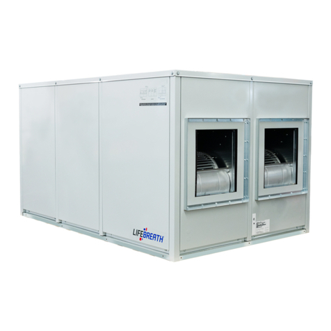
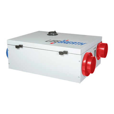
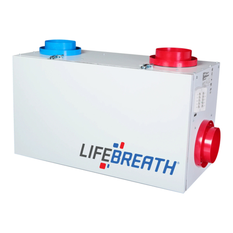
Lifebreath 700 POOL Specification sheet

69-POOL
100516
Indoor Pool and Spa Heat Recovery Ventilators (HRV)
Models 700POOL , 1200POOL
Operation and Installation Manual
Lifebreath Pool Room HRVs provide fresh clean air without sacrificing the savings of your energy conserving
home. The aluminum cores of the HRV provide effective and efficient heat recovery and air exchange.
Models
700POOL
1200POOL

2
Introduction
The Recovery Core....................................................3
Unit Specifications .................................................4-5
Calculating the Ventilation Rate for the Pool Room.......6
Table 1 - Evaporation Rate.........................................7
Table 2 - Flow Rate Factor.........................................8
Location of the HRV for Mounting...............................9
The Ductwork System
Outside Weatherhoods.............................................10
Sample Duct Layout 1..............................................11
Sample Duct Layout 2..............................................12
Mode of Operation for the Pool HRV .........................13
Stale Air Return System
Fresh Air Supply System
Adjustable Grilles......................................................14
Reversing the Supply and Defrost Air Ports ................15
Function and Controls ..............................................16
Drain Connections....................................................19
Electrical Connections
Balancing the HRV ...................................................20
Make Up Heat
Defrost Time Adjustment...........................................21
Maintenance and Service .....................................22-23
Troubleshooting Your HRV System ............................26
Wiring Diagram.........................................................27
Warranty..................................................................28
Leave this manual with your customer!
Installing Contractor
Telephone / Contact
Serial Number
Installation Date Model
TO BE CO PLETED BY CONTRACTOR AFTER INSTALLATION
Table of Contents
Reverse Installation of the HRV ............................24-25
Never install an HRVin a situation where its
normal operation, lack of operation or partial
failure may result in the backdrafting or
improper functioning of vented combustion
equipment!
It is always important to assess howthe
operation of any HRV may interact with vented
combustion equipment (ie. GasFurnaces, Oil
Furnaces, Wood Stoves, etc.).
Do not apply electrical power to the unit
until installation has been fully completed
(including low voltage control wiring).
CAUTION
CAUTION
Pool room air/surfaces MUST have a heating
appliance which does NOT include the pool
water as its source. The pool room and water
MUST be continuously operated at its original
design as any deviation from this could
greatly effect the operation of the unit.
The pool unit MUST be fully commissioned
after installation which includes confirming
proper operation of the control, normal
operation of the unit and drainage through the
pans without unintentional leakage.
CAUTION
Optional 3 Speed Control
Lifebreath Dehumidistat ...........................................17
Connecting Controls .................................................18

3
Introduction
The Recovery Core
High indoor humidity levels pose two threats to your
pool room environment: health (IAQ) and building
degradation.
Humidity control is provided by an adjustable
dehumidistat that is mounted in the pool room.
The dehumidistat (included with the pool HRV)
would be set to an acceptable humidity level (for
example, in a range of 40% to 50% R.H.).
Ventilation (the exhaust of humid indoor air and
introduction of the dryer outdoor air) occurs when
the adjustable HRV dehumidistat exceeds the set
point.
When the humidity level of the pool room falls below
the dehumidistat setpoint, the pool room air is
recirculated by the HRV (no outside air will enter the
system). Outside air is prevented from entering the
HRV during recirculation by the supply damper closing
off. The exhaust fan to the outside is shut off during
this recirculation mode. Outside air does not enter the
system again until the pool room humidity exceeds the
setpoint of the dehumidistat.
HRV - Aluminum Core
A Heat Recovery Ventilator (HRV) is designed to
provide fresh air into a building while exhausting an
equal amount of stale air. During the winter months,
the incoming cold fresh air is warmed by utilizing the
heat recovered from the stale air before it is
exhausted to the outdoors. During summer months
when the indoor space is air conditioned, the Heat
Recovery Ventilator will help in cooling the incoming
fresh air with the stale air that is being exhausted.
Fresh
Outdoor Air
Stale Air
to Outside
Stale Air
from Pool Room
Fresh Air
to Pool Room

AIRFLOWS (Each Air Stream)
AIRFLOW CFM (L/s)
0
100 (42)
200 (94)
300 (143)
400 (190)
500 (235)
600 (282)
700 (329)
800 (378)
900 (425)
0,1 0,2 0,3 0,4 0,5 0,6 0,7 0,8 0,9 1,0
(25) (50) (75) (100) (125) (150) (175) (200) (225) (250)
PERFOR ANCE
Date: ___________________________________________
Tag: _____________________Qty:___________________
Project: _________________________________________
Engineer: _______________________________________
Contractor: ______________________________________
Supplier: ________________________________________
Quote#: _________________________________________
Submitted by: ____________________________________
4
70%
60%
50%
AIRFLOW IN CFM (L/s)
EFFECTIVENESS
300
(143)
400
(190)
500
(235)
600
(282)
700
(329)
AHRI 1060 Certified Core:
Contains two 68-222
Specifications 700POOL
WARRANTY
Units carry a 15 year warranty
on the HRV core and a 2 year
replacement parts warranty.
DI ENSIONS inches (mm)
NOTE:
The 700POOL model may easily be
reversed in the field. Refer to page 29
for installation instructions.
All units conform to CSA and UL
standards
NOTE: All specifications are subject
to change without notice.
NOTE: Service clearance of 30 in. (760 mm) from front access doors
High Speed
Med Speed
Low Speed
EXTERNAL STATIC
PRESSURE
IN.
W.C.
(PASCALS)
TEMPERATURE EFFECTIVENESS
CONTROL OPTIONS
99-500 3 Speed Control
•3 Speed Fan setting (Low/Medium/High)
•4 wire connection; 20 gauge wire (minimum)
•
CORES
Modular (2 section) patented aluminum heat recovery cores arranged for
efficient counter-flow ventilation
MOTORS
Two PSC, 3 speed single shafted, 120 VAC, 4.5 Amps each (9 total on high
speed). HP - 1/4, 1450 RPM. Watts - total on high speed - 1032. MCA: 11.3
MOP: 15
FILTERS
Washable air filters in exhaust and supply air streams.
BLOWERS
Slide easily in / out of unit. Centrifugal type rated at 700 cfm (329 L/s) free
air delivery. Each air stream has one single shafted motor driving a
centrifugal blower.
CONNECTION DUCT SIZES
Five - 14" x 8" H (356 mm x 200 mm H).
MOUNTING
Unit to be set on support brackets hung by threaded rod type apparatus.
(brackets and rod not provided.)
CASE
Unit has front and back access doors and electrical panel can be switched to
either side giving installer flexibility in duct direction. 20 gauge prepainted
galvanized steel (G60) for superior corrosion resistance. Insulated with
elastomeric insulation where required to prevent exterior condensation, mold
and energy loss.
Drain connections; two - 1/2" (12mm) O.D.
ELECTRONICS
Integrated microprocessor circuit board. Built-in interlock contacts.
DEFROST
Supply bypass routes indoor air to defrost core.
WEIGHT 260 LBS (118 KG) SHIPPING WEIGHT 310 LBS. (141 KG)
INCLUDED CONTROL
99-DH01 Lifebreath Dehumidistat
•
Humidity control through adjustable Dehumidistat
3 wire connection; 20 gauge wire (minimum)
FILTER OPTIONS
99-65-183 2" pleated MERV 8 filter for fresh air stream

INLET SIDE
DISCHARGESIDE
EXHAUST AIR
FROM
BUILDING
AIRFLOW CFM (L/s)
70%
60%
50%
AIRFLOWINCFM(L/s)
EFFECTIVENESS
0,0 0,1 0,2 0,3 0,4 0,5 0,6 0,7 0,8 0,9 1,0
(0) (25) (50) (75) (100) (125) (150) (175) (200) (225) (250)
1600 (755)
1400 (660)
1200 (566)
1000 (472)
800 (378)
600 (282)
400 (190)
PERFOR ANCE
AIRFLOWS (Each Air Stream)
Date: ___________________________________________
Tag: _____________________Qty:___________________
Project: _________________________________________
Engineer: _______________________________________
Contractor: ______________________________________
Supplier: ________________________________________
Quote#: _________________________________________
Submitted by: ____________________________________
5
)52179,(:
EXHAUST AIR
TO OUTSIDE
SUPPLY AIR
TO BUILDING
500
(235)
600
(282)
700
(329)
800
(378)
900
(423)
1000
(472)
1100
(518)
1200
(566)
CORES
Modular (3 section) patented aluminum heat recovery cores arranged for
efficient counter-flow ventilation
MOTORS
Two PSC, 3 speed double shafted, 120 VAC, 9.4 Amps each (18.8 total on
high speed). HP - 1/2, 1625 RPM. Watts - total on high speed - 2256. MCA:
23.5 MOP: 30
FILTERS
Washable air filters in exhaust and supply air streams.
BLOWERS
Slide easily in / out of unit. Centrifugal type rated at 1200 cfm (566 L/s)free
air delivery. Each air stream has one double shafted motor driving 2
centrifugal blowers.
CONNECTION DUCT SIZES
Five - 20" x 8" H (508 mm x 200 mm H)
MOUNTING
Unit to be set on support brackets hung by threaded rod type apparatus.
(brackets and rods not provided)
CASE
Unit has front and back access doors and electrical panel can be switched to
either side giving installer flexibility in duct direction. 20 gauge prepainted
galvanized steel (G60) for superior corrosion resistance. Insulated with
elastomeric insulation where required to prevent exterior condensation, mold
and energy loss.
Drain connections; two - 1/2" (12mm) O.D.
ELECTRONICS
Integrated microprocessor circuit board. Built-in interlock contacts.
DEFROST CONTROLS
Supply bypass damper routes indoor air to defrost core
WEIGHT 285 LBS (130 KG) SHIPPING WEIGHT 335 LBS. (152 KG)
INCLUDED CONTROL
$+5,&HUWLILHG&RUH
Contains three 68-222
Specifications 1200POOL
WARRANTY
Units carry a 15
year warranty on the
HRV core and a 2
year replacement
parts warranty.
DI ENSIONS inches (mm)
NOTE:
The 1200POOL model may
easily be reversed in the field.
Refer to page 29 for
installation instructions.
NOTE: All specifications are
subject to change without
notice.
All units conform to CSA and UL standards
NOTE: Service clearance of 30 in. (760 mm) from front access doors
High Speed
Med Speed
Low Speed
EXTERNAL STATIC PRESSURE IN in. W.C. (PASCALS)
TEMPERATURE EFFECTIVENESS
CONTROL OPTIONS
99-500 3 Speed Control
•3 Speed Fan setting (Low/Medium/High)
•4 wire connection; 20 gauge wire (minimum)
99-DH01 Lifebreath Dehumidistat
•Humidity control through adjustable Dehumidistat
•3 wire connection; 20 gauge wire (minimum)
FILTER OPTIONS
99-65-183 2" pleated MERV 8 filter for fresh air stream
Other manuals for 700 POOL
1
This manual suits for next models
1
Table of contents
Other Lifebreath Heating System manuals

Lifebreath
Lifebreath METRO 120D User manual

Lifebreath
Lifebreath 350 DGS User manual

Lifebreath
Lifebreath 1500I-ECM User manual

Lifebreath
Lifebreath 155 MAX 2019 User manual

Lifebreath
Lifebreath 350DCS Specification sheet

Lifebreath
Lifebreath RNC series Specification sheet

Lifebreath
Lifebreath 1500I-ECM User manual
Popular Heating System manuals by other brands

Truma
Truma Trumatic E 2400 E Operating instructions and installation instructions

Aqua-Hot
Aqua-Hot 200 Series installation manual

Vent-Axia
Vent-Axia HR100S Installation and maintenance instructions

aerauliqa
aerauliqa QR350ABP installation manual

WatchGas
WatchGas ATEX BEACON manual

Lampoassa
Lampoassa 203GT user manual