Lifebreath RNC series Specification sheet

69-RNC
1011
Residential New Construction Series (RNC)
Heat Recovery Ventilators
Operation and nstallation Manual
RNC Series
RNC155
RNC200* RNC95*
RNC10
RNC20
2 Speed Electronics
RNC5-TPD*
RNC120D
This product earned the E ERGY STAR by
meeting strict energy efficiency guidelines set by
atural Resources Canada and the US EPA. It
meets E ERGY STAR requirements only when
used in Canada.
*

Introduction
Warranty........................................................................................2
etting to Know your RNC Series HRV
Selecting the Ventilation Rate that is right for You
How the Dehumidistat Works
lossary and Additional Information
Warranty........................................................................................3
The Lifestyle RNC Digital Control...............................................4
The Lifestyle Dehumidistat
The Lifestyle RNC Ventilation Control........................................5
Optional Timers ............................................................................6
Maintenance Routine for your HRV .............................................7
Technical Data - Model RNC95 ................................................8-9
Technical Data - Model RNC155 ...............................................10
Technical Data - Model RNC200 ...............................................11
Technical Data - Model RNC10 .................................................12
Technical Data - Model RNC20 .................................................13
Technical Data - Model RNC5-TPD...........................................14
Technical Data - Model RNC120D.............................................15
Engineering Data - HRV.............................................................16
Installation Methods and Installation Diagrams ....................17-20
Installation...................................................................................21
Suspending the RNC120D ..........................................................22
Drain Connection and rilles .....................................................23
rille Fittings .............................................................................24
Weatherhood Installation ............................................................25
Installation of the Main Control..................................................26
Installation and Operation of 20 Minute and
20/40/60/ Minute Timers
Installation of Mechanical Timers...............................................27
Interlocking HRV Operation to an Airhandler/Furnace Blower
Setting “Standby” when using a Main Control
Operating the HRV without a Main Control and
Adding Dry Contacts..................................................................28
Balancing Air Flows ...................................................................29
Balancing the Air Flows with a Pitot Tube.................................30
Air Flow Balancing using the Door Ports..............................31-32
Balancing Dampers
Balancing Instruments and Kits ..................................................33
Troubleshooting your HRV System............................................34
Wiring Diagrams....................................................................35-38
2
Table of Contents
MPORTANT -
PLEASE READ TH S MANUAL
BEFORE NSTALL NG UN T.
CAUTION
Before installation, careful consideration must be
given to how this system will operate if connected
to any other piece of mechanical equipment, i.e. a
forced air furnace or air handler, operating at a
higher static. After installation, the compatibility of
the two pieces of equipment must be confirmed, by
measuring the air flows of the HRV, by using the
balancing procedure found in this manual.
NEVER install a ventilator in a situation where its
normal operation, lack of operation or partial
failure may result in the backdrafting or improper
functioning of vented combustion equipment.
WARNING
• Disconnect the power from the unit before
cleaning or servicing.
• To prevent electrical shock, it is extremely
important to confirm the polarity of the power line
that is switched by the safety (disconnect) switch.
The hot line (black) is the proper line for switching.
Use either a voltmeter or test lamp to confirm the
absence of a voltage between the disconnect
switch and ground (on the cabinet) while the door
is open. This procedure must be followed, as
dwellings are occasionally wired improperly.
Always enure the proper grounding of the unit.
• Do not apply electrical power to the unit until after
the completion of the installation (including the
installation of low voltage control wiring).
• Ensure the nstallation and wiring is in
accordance with CEC, NEC, and local electrical
codes.
• Due to ongoing research and product
development, specifications, ratings and
dimensions are subject to change without notice.
•Plug the unit into a standard designated (120 VAC)
electrical outlet with ground.
•The use of an extension cord with this unit is not
recommended. f the installation requires further
wiring, have a licensed electrician make all of the
electrical connections. The recommended circuit is a
separate 15 amp/120 volt circuit.
• Due to ongoing research and product
development, specifications, ratings and
dimensions are subject to change without notice.

3
Thank you for purchasing a LIFEBREATH® Heat Recovery Ventilator
(HRV). The HRV provides fresh air to your home while recovering
energy from the air it exhausts.
There are numerous benefits to a properly installed, operated, and
maintained HRV:
• exhausts the stale, contaminated air, found in today’s tight buildings.
• recovers the majority of the energy contained in the exhausted stale air.
• uses the recovered energy to preheat or precool the fresh outdoor air
introduced into the house
.• distributes the fresh air throughout your home.
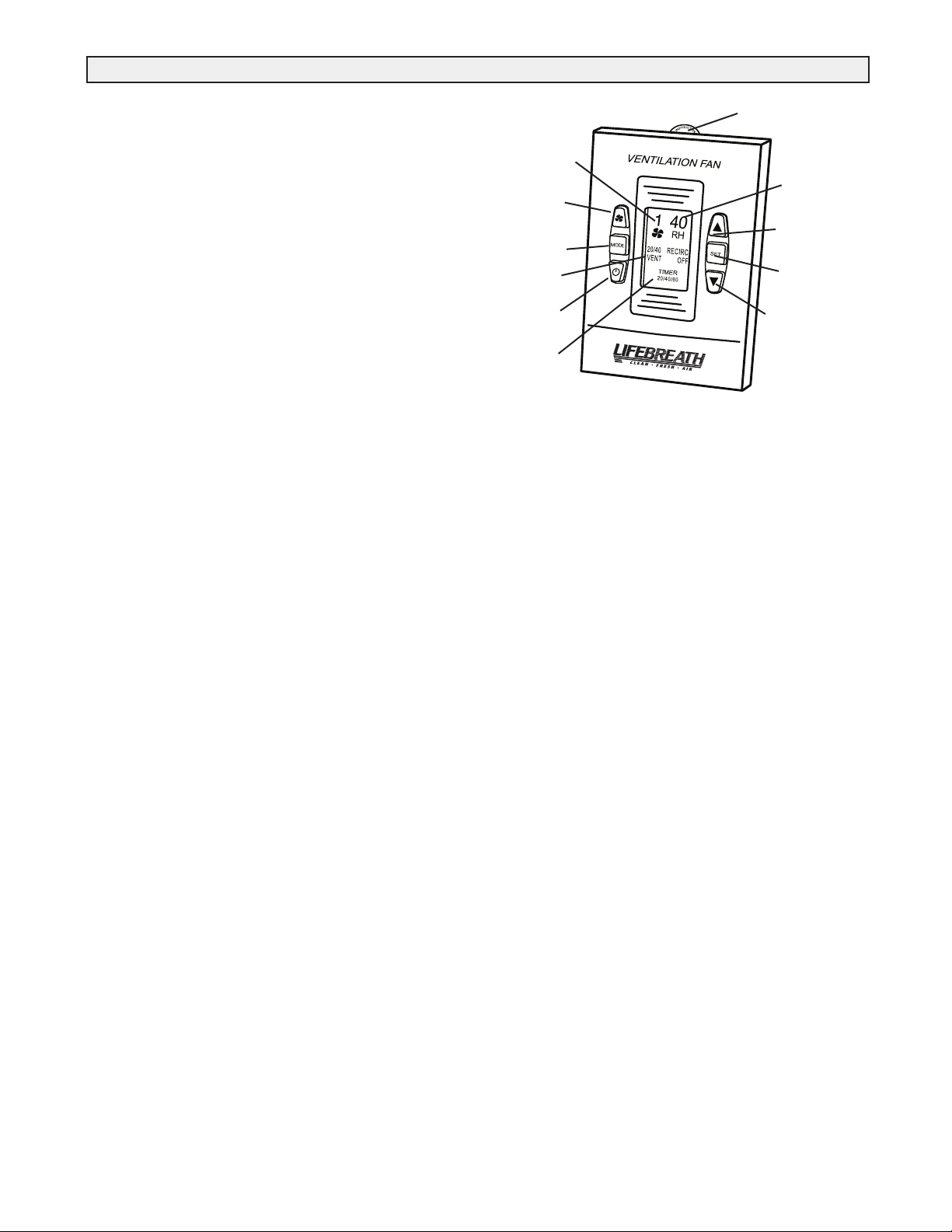
Getting to Know your RNC Series Heat Recovery Ventilator (HRV)
Your Lifebreath RNC SERIES HRV has several optional controls.
Experiment with the ventilation levels in your home to evaluate the ideal
amount of ventilation to suit your home and personal preferences.
. CONT NUOUS VENT LAT ON
This mode of operation provides continuous ventilation within the home.
You may, for example, select Continuous Ventil tion at a low speed (speeds
1 or 2) for normal operation and increase to a higher speed (speeds 3 to 5)
during increased activity levels, such as cooking and showering, etc.
. 20 M NUTES ON, 40 M NUTES STANDBY
This mode of operation provides 20 minutes of ventilation each hour. You
can use this ventilation mode at low speed for low household
activity levels or when the home is unoccupied. This feature is
unavailable on some controls.
. 20 M NUTES ON, 40 M NUTES REC RCULAT ON *
Ventilates for 20 minutes and recirculates the household air every
40 minutes each hour. This mode is non-applicable if your HRV is
connected to a forced air system (the forced air system already circulates
household air).This feature is unavailable on some controls.
V. CONT NUOUS REC RCULAT ON *
Continuously recirculates your household air (no ventilation). This mode is
non-applicable if your HRV is connected to a forced air system.This feature
is unavailable on some controls.
* If your HRV is connected to a forced air system, recirculation (modes III
and IV) is unavailable and non-applicable on all models.
REC RCULAT ON - recirculates existing household air without
introducing fresh air. Recirculation Modes (III and IV) are
non-applicable if your HRV is connected to a forced air system, since your
forced air system already circulates the household air. Recirculation Modes
are unavailable on some models.
Selecting the Ventilation Rate that is right for You
High indoor humidity levels, during the heating season, have become a
problem in many well insulated, tight homes. Excessive condensation on the
windows is a visual sign of high indoor humidity levels. High indoor
humidity levels can result in mold and mildew and the eventual
degradation of the building structure itself.
Your HRV reduces indoor humidity levels when the outdoor air is drier
than the indoor air. These conditions usually occur during the
heating season when outdoor temperatures are less than 15°C (59°F). During
the heating season, the operation of the HRV may reduce indoor humidity
levels sufficiently to eliminate the need for further dehumidification.
If your home requires further dehumidification, use the dehumidistat
feature located on any optional main control (refer to the Operation and
Installation Manual for Optional Control information). This feature
aggressively addresses high indoor humidity levels by initiating high speed
ventilation when the indoor humidity levels rise above the
adjustable set point on the control.
Refer to the main control instructions located in the Oper tion nd
Inst ll tion M nu l for instructions on how to set the dehumidistat.
The dehumidistat function on the main control should be set to OFF for all
seasons except the heating season, because a dehumidifying effect
occurs only when the outdoor air is dryer than the indoor air. Set the RH
level to 80 to turn the dehumidistat OFF. (Refer to the control
instructions for information on how to set the Dehumidistat).
DEHUMIDISTAT DISABLE - automatically disables the dehumidistat
function on the main control when outdoor temperatures exceed 15°C
(59°F) for a full 24 hour period. All other HRV features and functions
operate normally while the dehumidistat function is disabled.
DEHUMIDISTAT RE-E ABLE - automatically re-enables the
dehumidistat function if either the outdoor temperature drops below 15°C
(59°F) for a full 24 hour period or if the HRV is reset (unplugged for
30 seconds).
How the Dehumidistat Works
DEFROST MODE - To ensure reliable operation during cold weather, the
HRV automatically cycles through its defrost mode when the outdoor
temperatures drop below freezing.
HRV - a Heat Recovery Ventilator (HRV) is designed to provide fresh air
into a building while exhausting an equal amount of stale air. During the
winter months, heat recovered from the stale air, before it is
exhausted to the outdoors, warms the incoming cold fresh air. During the
summer months, when the indoor space is air conditioned, the HRV helps to
cool the incoming fresh air with the cool exhausted stale air.
MAI TE A CE ROUTI E - Homeowner maintenance should be
performed as per "M inten nce Routine for HRV" located in the
Oper tion nd Inst ll tion M nu l.
OPTIO AL CO TROLS - A selection of Optional Controls is available
for the HRV. Refer to the Operation and Installation Manual for more
information.
OPERATIO A D I STALLATIO MA UAL - Contains
instructions and important information regarding your HRV and controls.
You can download the manual at www.lifebreath.com.
SELF-TEST - Each time the HRV is powered/energized, the self-test
function automatically initiates. The HRV cycles through the available
speeds and tests the damper motor operation. The HRV defaults back to the
previous operational mode and speed selection after the self-test
(approximately 60 seconds in duration).
STA DBY (Speed 0) - The HRV is powered/energized and waiting for
ventilation to be initiated by either an external control (i.e. timer) or the
dehumidistat. Set the main control to speed 0 to set the HRV in standby.
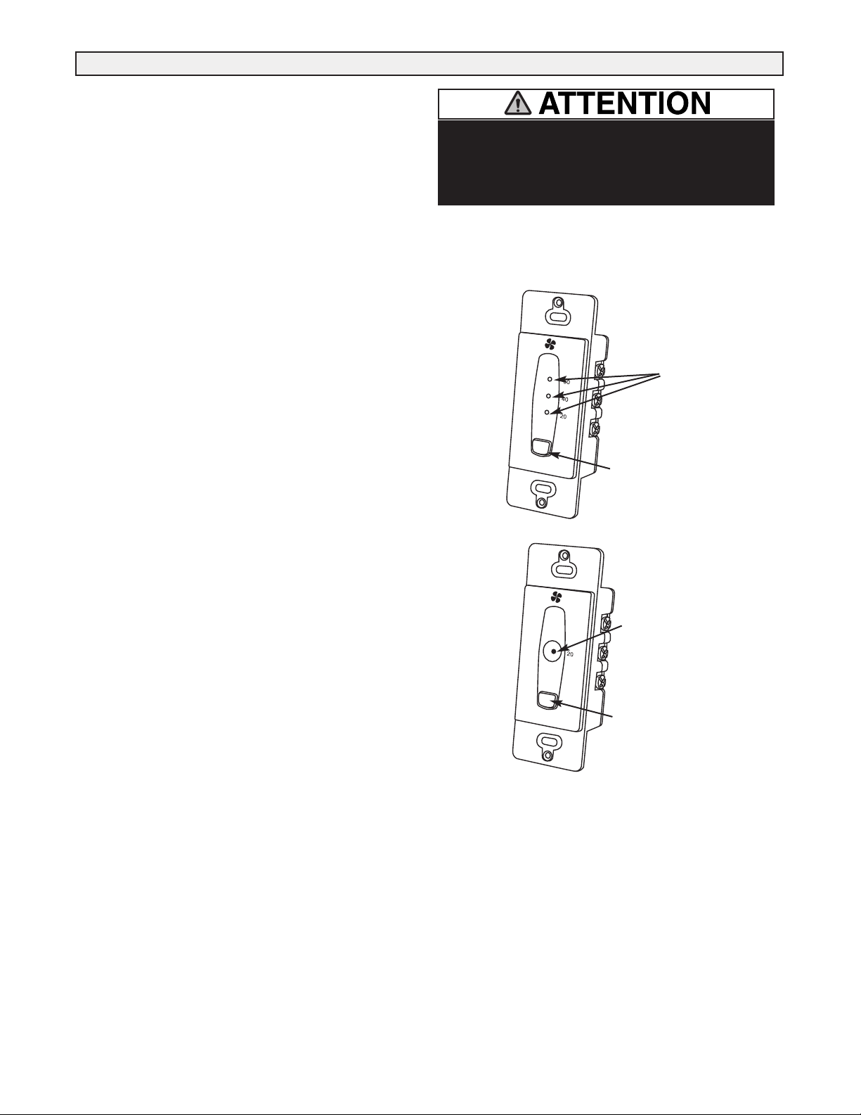
TIMERS - These optional controls may be installed at specific exhaust
locations (bathrooms etc.) to initiate high speed ventilation.
Lifebreath RNC Series Heat Recovery Ventilators carry a Lifetime
Warranty on the heat recovery core and a 5 (five) year replacement parts
warranty.
Register for your warranty at:
www.lifebreath.com or phone 1-855-247-4200 (toll free)
OTE: You will require the HRV Model and Serial Number to register.
Glossary and Additional nformation
Warranty

The Lifestyle RNC Digital Control Part #99-DX-01
Part # 99-DX-01
The Lifestyle RNC Digital Control offers advanced features to
control your home's ventilation.
Key Features
• 2 Speed Fan setting (Low-1/High-2)
• Standby setting (Fan speed 0)
• Electronic Dehumidistat
• Four Selectable Modes of Operation
20 min. ON / 40 min. off, 20 min. ON / 40 min. recirculate *
Continuous Ventilation, Continuous Circulation *
• 20 / 40 /60 High Speed override button
• Instruction Card is inserted in the control
• Easy to read LCD Screen
• Slim-line design
• Connect to 3 wire 20 gauge low voltage wire
Setting the Control
1. Refresh the screen: use the ON/OFF button to turn the control
OFF and ON.
2. Press the SET button.
3. The “FAN” symbol flashes. SCROLL (by using the Up/Down
arrows) to select the desired fan speed (0, 1 or 2). Press the
SET button.
4. “VENT”, “20/40”, “20/40 RECIRC”, “RECIRC”or “OFF” will
flash. SCROLL to select the desired mode of operation. Press
SET button. *RECIRC is not available on all models.
**Timers will not function when mode of operation is set to
“OFF”.
Setting the Dehumidistat
1. Refresh the screen: use the ON/OFF button to turn the control
OFF and ON.
2. Press and release MODE until “RH” flashes.
3. SCROLL to the desired RH number. Press the MODE button.
20/40/60 Minute High Speed Timer
This function temporarily initiates high speed ventilation for
20, 40 or 60 minutes.
1. Refresh the screen: use the ON/OFF button to turn the control
OFF and ON.
2. Press FAN button once for 20, two times for 40, three times for
60 minutes, and four times to cancel the timer.
The Lifestyle RNC Digital Control Gives you
4 Mode Selection
The Lifestyle RNC Digital Control has 4 Operational Modes* and
2 speeds on each mode to adjust indoor ventilation levels.
Experiment with the ventilation levels in your home to evaluate
the best amount of ventilation to suit your home and preferences.
. Continuous Ventilation Mode
This is the most popular mode since it provides continuous
ventilation within the home. You may, for example, select
Continuous Ventilation at high speed for high household
activity levels or Continuous Ventilation for lower activity
levels.
. 20 minutes ON, 40 minutes OFF Mode
This Operational Mode will provide 20 minutes of ventilation
each hour. You may wish to use this ventilation mode in low
speed for low household activity levels or if the home is
unoccupied.
. 20 minutes ON, 40 minutes Recirculation
Mode*
This Operational Mode provides 20 minutes of ventilation
(fresh air) and 40 minutes of recirculated air. Use this mode
only if your HRV is not connected to a forced air system (the
forced air system already circulates household air).
V. Continuous Recirculation Mode*
This Operational Mode recirculates your household air (no
ventilation). Use this mode only if HRV is not connected to a
forced air system.
How to Synchronize the Humidity Setting on the
Lifestyle RNC Digital Control
The Lifestyle RNC Digital wall control has a feature that will
allow it to be synchronized with other humidity instruments in
your home.
1. Turn off the control with the ON/OFF Button.
2. Simultaneously press and release the ON/OFF Button and the
20/40/60 Minute High Speed Override Button.
3. Use the Up/Down buttons to adjust the Humidity indicator on
the display screen to the number of degrees difference between
your humidity measuring devise. Minus is indicated by
flashing.
4. Press the MODE button.
*Recirculation not available on all models.
nstruction card
Fan Speed
ndicator
20/40/60 Minute
High Speed
override Button
Mode Select
Button
ON/OFF
Button
High Speed
Override
Timer
ndicator
Humidity
ndicator
Up Button
Set button
Down Button
Mode
ndicator
Connects to 3 wire 20 gauge
low voltage wire
4

Key Features
• The Dehumidistat measures the indoor humidity level and will
initiate high speed ventilation when the moisture level in the
home exceeds the set point on the control.
• Once the humidity in the house is reduced, the HRV will revert
back to its previous setting.
• The Dehumidistat should be set to OFF for all season except the
heating season.
• Connect to 3 wire 20 gauge low voltage wire.
Humidity Control
Your HRV will produce a dehumidifying effect when outdoor
humidity levels are lower than indoor humidity levels. Never use
the dehumidistat feature when outdoor temperatures are above 59
F (15 C).
Note: The indoor humidity level is measured at the control.
Setting the Dehumidistat
Press and release the DEHUMIDISTAT button until the
DEHUMIDISTAT LI HT is at the desired setting. After 5
seconds the dehumidistat light will either flash or be on
continuous.
A flashing light indicates the humidity level is higher than the
setting and the unit is operating on high speed ventilation. A
continuous light indicates the humidity level is lower than the
setting. Refer to the unit's Operation & Installation Manual for
instructions on how the Dehumidistat works.
Note - Only 1 dehumidistat should be active on a system.
The Lifestyle Dehumidistat Part #99-DH-01
The Lifestyle RNC Ventilation Control Part #99-BC-01
%
80
20
nstruction card
Dehumidistat ndicator
LEDs
Set to the desired humidity
level. High speed ventilation
will initiate when the indoor
moisture level exceeds the set
point on the control.
Dehumidistat
Adjust button
The Lifestyle RNC Ventilation Control offers ON/OFF, High
Speed/Low speed plus an electronic dehumidistat.
Key Features
• 2 Speed Fan setting (Low/High)
• Electronic Dehumidistat
• Instruction Card is inserted in the control
• Slim-line design
• Connect to 3 wire 20 gauge low voltage wire.
Turning on the Control
Press and release the ON/OFF button. The "ON Indicator Light"
will illuminate.
Adjusting the Ventilation Speed
The unit will normally operate at low speed. Press and release the
SPEED button to initiate high speed ventilation. The "High Speed
Indicator LED" will illuminate.
Humidity Control
Your unit will produce a dehumidifying effect when outdoor
humidity levels are lower than indoor humidity levels. Never use
the dehumidistat feature when outdoor temperatures are above 59
F (15 C).
Setting the Dehumidistat
Press and release the DEHUMIDISTAT button until the
DEHUMIDISTAT LED is at the desired setting. After 5 seconds
the dehumidistat light will either flash or be on continuous.
A flashing light indicates the humidity level is higher than the
setting and the unit is operating on high speed ventilation. A
continuous light indicates the humidity level is lower than the
setting. Refer to the unit's Operation & Installation Manual for
instructions on how the Dehumidistat works.
Note - Only 1 dehumidistat should be active on a system.
%
80
20
HIGH
nstruction card
Dehumidistat
ndicator LEDs
ON/OFF
button
High/Low
Speed
button
High Speed
ndicator LED
On
indicator
light
*Install a jumper between 2 (ON) and 3 (RED) on the HRV terminal
block to configure the ON/OFF button to ON/STANDBY. Refer to
“Setting Standby when using a Main Control” in this manual.
If the system does not have a main control installed, the HRV Terminal
Block must have a jumper installed between 2 (ON) and 3 (RED). Refer
to “Operating the HRV without a Main Control” in this manual.
5

The timer will override the Operational Mode (regardless of the
setting) and initiate high speed ventilation. Upon completion of the
timer cycle, the HRV will return to your selected Operational
Mode and speed setting.
Lifestyle 20/40/60 Minute Timer
Part # 99-DET01
Initiates high speed ventilation for 20, 40 or 60 minutes. The
20/40/60 Minute Status Lights indicate high speed operation.
Lockout Mode is useful if you wish to disable the timer. Set
lockout by holding the Select Button for 5 seconds. Unlock by
holding for 5 seconds.
Lifestyle 20 Minute Timer
PART O. 99-20M01
Initiates high speed ventilation for 20 minutes. The 20 Minute
Status Light indicates high speed operation.
Lockout Mode is useful if you wish to disable the timer. Set
lockout by holding the select button for 5 seconds. Unlock by
holding for 5 seconds.
Optional Timers
Select Button
Select Button
20/40/60 Minute
Status Lights
20 Minute
Status Lights
If the system does not have a main control installed, the HRV
Terminal Block must have a jumper installed between 2 (ON)
and 3 (RED). Refer to “Operating the HRV without a Main
Control” in this manual.
6

1. nspect Exterior Hoods at least once a month.
Make sure exhaust and fresh air supply hoods are not blocked or
restricted by leaves, grass, or snow. In winter, it is especially
important to make sure snow is not blocking the hoods or that frost
has not built up on the wire mesh (bird screen).
WARIG: Block ge of hoods m y c use n imb l nce.
2. Clean Air Filters (clean twice a year)
The standard filters equipped with your HRV are removable and
washable.
a) simply open access door and slide core out
b) remove filter clips
c) once clips are removed filters can be taken off the core to be
rinsed with water or a combination of mild soap and water. Do
not clean in the dishwasher
d) to re-assemble, place clean filter(s) (wet or dry) back into their
positions against the core and return clips to their original
position
e) slide core back into its’ original position
3. Clean Core Twice a Year
a) open access door.
b) carefully grip ends of core and pull evenly outward. Core may
be snug, but will slide out of the channel
c) once removed from the cabinet remove filters
d) wash core in warm soapy water (do not use dishwasher)
e) install the clean filters
f) install clean core
ote: Core inst ll tion l bel on the outer end of the core.
To install the clean core:
a) first mount the bottom flange of the core guide into the bottom
H channel approximately 1/4” (6mm)
b) mount the left or right side flange of the core guide
approximately 1/4” (6mm) followed by the other side
c) mount the top flange of the core guide into the top H channel
approximately 1/4” (6mm).
d) with all four corners in place and the core straight and even,
push hard in the centre of the core until the core stops on the
back of the cabinet.
OTE: Core will ppe r to stick out from c binet pproxim tely 1/8”
(3mm). This is designed this w y so th t the ccess door will fit tight
g inst the core.
4. Motors - Maintenance Free
5. Drain (condensate) Line - Clean once a year
Inspect drain line, drain spout and “P” trap for blockage, mould or
kinks. Flush with warm soapy water and replace if worn, bent or
unable to clean.
6. Clean Duct Work if Required
The duct work running to and from the HRV may accumulate dirt.
Wipe and vacuum the duct once every year. You may wish to
contact a Heating/Ventilation company to do this.
7. General Maintenance - Twice a Year
Wipe down the inside of the cabinet with a damp cloth to remove
dirt, bugs and debris that may be present.
8. Cleaning the Fans
Fans may accumulate dirt causing an imbalance and/or excessive
vibration of the HRV. A reduction in the air flow may also occur.
In new construction this may result within the first year due to
heavy dust and may occur periodically after that over time
depending on the outdoor conditions.
• unplug the HRV and open the service door
• remove the core
• remove ducting (metal and/or flexible insulated type) from
the red and/or blue ports which are connected immediately
in-line with the fan assembly
• use a small brush, such as an old toothbrush or pipe cleaner,
and insert first
(a) through the large opening of the fan
assembly and then
(b) through the smaller opening in the end
of the fan assembly.
• scrub individual fan blades until clean. Avoid moving or
damaging balancing flat weight, clip is usually found on one
or more of the fan blades
• vacuum and wipe
• reassemble making sure ducting is reattached firmly and
insulation and moisture barrier are sealed and taped
Before ttempting this t sk, thought should be given to h ving
qu lified service technici n complete the service work.
Maintenance Routine for HRV
Electric shock hazard.Cancause
injury or death. Before attempting to
perform any service or maintenance,
turn the electrical power unit OFF at
disconnectswitch(es).Unit may
have multiple power supplies.
WARNING
7

THERMALLY CONDUCT VE, PATENTED ALUM NUM CORE
The cross-flow heat recovery core transfers heat between the two airstreams. It is easily
removed for cleaning or service.
MOTORS AND BLOWERS
Each air stream has one centrifugal blower driven by a common PSC motor. 2 speed fan
operation.
F LTERS
Washable air filters in exhaust and supply air streams.
MOUNT NG THE HRV
Four threaded inserts at corners of the cabinet designed to accept the “S” hooks and hanging
straps supplied with the unit.
DEFROST
Recirculating defrost system.
CASE
Twenty gauge prepainted galvanized steel ( 60) for superior corrosion resistance. Insulated
to prevent exterior condensation. Drain connections 2 - 1/2" (12 mm) OD.
WE GHT 52 lbs. (23.6 kg) SH PP NG WE GHT 56 lbs (25.4 kg)
RNC SER ES ELECTRON CS
• Built-in Relay for Interfacing to furnace
• A standard ON/OFF switch can be added to provide Low/High Ventilation or ON/OFF
functionality in order to meet building standards.
• Optional controls can be installed at the time of the installation or at a later date to upgrade
the basic features of the ventilation system.
OPT ONAL CONTROLS
99-DX-01 Lifestyle R C Digital Control
• 2 Speed Operation on each mode • 4 user selectable operational modes: Continuous
Ventilation, 20 ON/40 OFF, 20 ON/40 Recirculation, Continuous Recirculation
• Adjustable Dehumidistat function built into the main wall control
• Connect to 3 wire 20 gauge low voltage wire.
99-BC-01 Lifestyle R C Ventilation Control -
• 2 Speed Fan setting (Low/High) • Dehumidistat
• Connect to 3 wire 20 gauge low voltage wire.
OPT ONAL T MERS
99-DET01 Lifestyle 20/40/60 Minute Timer - Initiates high speed ventilation for
20, 40, or 60 minutes, (3 wire) 20 gauge wire (min.) 100' length
99-20M01 Lifestyle 20 Minute Timer - Initiates high speed ventilation for 20 minutes,
(3 wire) 20 gauge wire (min.) 100’ length.
99-101 Mechanical Timer - Initiates High speed ventilation for up to 60 minutes,
(2 wire) 20 gauge wire (min.) 100' length
OPT ONAL ACCESSOR ES
99-DH-01 Lifestyle Dehumidistat - Initiates high speed ventilation when the indoor
humidity level is above the set point. (3 wire) 20 gauge wire (min.) 100' length
99-163 Duct Heater w/ Electronic SCR Thermostat, 1 Kw, 6” (150 mm)
99-185 Weatherhoods, Two - 5” (125 mm) c/w 1/4” (6 mm) mesh screen
WARRANTY
Units carry a LIFETIME warranty on the heat
recovery core and a 5 year replacement parts
warranty.
All units conform to CSA and UL standards.
info@lifebreath.com
Date: ___________________________________________
Tag: _____________________Qty:___________________
Project: _________________________________________
Engineer: _______________________________________
Contractor: ______________________________________
Supplier: ________________________________________
Quote#: _________________________________________
Submitted by: ____________________________________
*Sensible Efficiency – thermal **Latent Efficiency – moisture
ote: Effectiveness - b sed on temp. differenti l between the 2 irstre ms
Efficiency – t kes into ccount ll power inputs
Performance (HV certified)
Net su ly air flow in cfm (L/s) against external static ressure
E.S.P
(external static pressure) [c m (L/s)]
@0.1" (25 Pa) 76 (36)
@0.2" (50 Pa) 73 (34)
@ 0.3" (75 Pa) 70 (33)
@ 0.4" (100 Pa) 66 (31)
@ 0.5" (125 Pa) 60 (29)
Max. Temperature Recovery 88%
Sensible Effectiveness
@ 60 cfm (28 L/s) 32°F (0°C) 88%
*Sensible Efficiency
@ 60 cfm (28 L/s) 32°F (0°C) 75%
*Sensible Efficiency
@ 61 cfm (29 L/s) -13°F (-25°C) 68%
VAC @ 60HZ 120
WATTS / Low speed. 59
WATTS / High speed 150
Amp rating 0.9
Static Pressure (in w.g.)
Air Flow(cfm)
Speed 2
Speed 1
20
30
40
50
60
70
0 0.1 0.2 0.3 0.4 0.5 0.6
80
1 - Low Speed
2 - High Speed
Removable
Heat Recovery
Core
Drain Pan
Drain spout
FRONT TOP
knockout for
side mounting of
EXHAUST return port
6" round collar
converted to oval
minimum
18 inches (459 mm)
required for
service access
Threaded
inserts (4)
at corners
SUPPLY
Fresh air
from outside
5" round collar
SUPPLY
Fresh air
to building
6" round
(conv. to oval)
collar
EXHAUST
Stale Air
to outside
5" round collar
EXHAUST
Return air
from building
Choice of port location
Knockouts on top and
side of unit (use 1 only)
6" round (conv.to oval)
collar supplied
18.5"
(470 mm)
18.5"
(470 mm)
16"
(406 mm)
SIDE
Hanging
straps (4)
24.5"
(622 mm)
D MENS ONS RNC95 inches (mm)
Model RNC95
8

Port Configuration and Airflow Model RNC95
RNC95 Port Specifications
The RNC95 Heat Recovery Ventilator (HRV) has been designed
to allow the installer to choose between two possible positions on
the cabinet for the INDOOR EXHAUST (return from building)
port. Illustrations in this manual show standard (side mounted)
port location. The same specifications apply to both RNC95
setups, regardless of which port position is selected.
Variable Port Location / nstallation
(Model RNC95 only)
The exhaust return port collar is not factory installed. Installer
may choose either side mounted or alternate top mounted port by
simply removing one of the two knock-out plates and attaching a
port collar (supplied). To remove knock-out plate, insert a utility
knife into the knock-out slits and trace them completely to
puncture protective film underneath. Then, cut the solid tabs
between the slits, using tin snips or side cutters, and remove the
knock-out plate. If any protective film still blocks the opening,
remove it now.
In order to make the RNC95 as space efficient as possible, the
INDOOR supply and return ports are converted from round to oval
shape. Overall size of the port remains the same. Simply bend a
standard duct fitting to the correct shape, and attach to the oval
port using the same method as for a round port.
RNC95 Air Flow
Stale air enters the FRONT RI HT side port. The air will pass
down the front half of the core, then up the back half of the core
and out the RI HT REAR port.
Fresh outdoor air will enter the LEFT REAR port and pass down
the back half of the core. It will then pass up the front half of the
core, and out the LEFT FRONT port. This unique configuration
allows the air to actually travel through the core twice, making the
RNC95 almost as efficient as a double core unit.
Variable Port Location
S DE MOUNTED PORT TOP MOUNTED PORT
standard location alternate location
Round port bent to oval
9

THERMALLY CONDUCT VE, PATENTED ALUM NUM CORE
The cross-flow heat recovery core transfers heat between the two airstreams. It is easily
removed for cleaning or service.
MOTORS AND BLOWERS
Each air stream has one centrifugal blower driven by a common PSC motor. 2 speed fan
operation.
F LTERS
Washable air filters in exhaust and supply air streams.
MOUNT NG THE HRV
Four threaded inserts at corners of the cabinet designed to accept the “S” hooks and hanging
straps supplied with the unit.
DEFROST
Recirculating damper defrost system.
CASE
Twenty gauge prepainted galvanized steel ( 60) for superior corrosion resistance. Insulated
to prevent exterior condensation. Drain connections 2 - 1/2" (12 mm) OD. Balancing ports
are located in the door.
WE GHT 71 lbs. (32.5 kg) SH PP NG WE GHT 73 lbs. (33.5 kg)
RNC SER ES ELECTRON CS
• Built-in Relay for Interfacing to furnace
• A standard ON/OFF switch can be added to provide Low/High Ventilation or ON/OFF
functionality in order to meet building standards.
• Optional controls can be installed at the time of the installation or at a later date to
upgrade the basic features of the ventilation system.
OPT ONAL CONTROLS
99-DX-01 Lifestyle R C Digital Control
• 2 Speed Operation on each mode • 4 user selectable operational modes: Continuous
Ventilation, 20 ON/40 OFF, 20 ON/40 Recirculation, Continuous Recirculation
• Adjustable Dehumidistat function built into the main wall control
• Connect to 3 wire 20 gauge low voltage wire.
99-BC-01 Lifestyle R C Ventilation Control -
• 2 Speed Fan setting (Low/High) • Dehumidistat
• Connect to 3 wire 20 gauge low voltage wire.
OPT ONAL T MERS
99-DET01 Lifestyle 20/40/60 Minute Timer - Initiates high speed ventilation for
20, 40, or 60 minutes, (3 wire) 20 gauge wire (min.) 100' length
99-20M01 Lifestyle 20 Minute Timer - Initiates high speed ventilation for 20 minutes,
(3 wire) 20 gauge wire (min.) 100’ length.
99-101 Mechanical Timer - Initiates High speed ventilation for up to 60 minutes,
(2 wire) 20 gauge wire (min.) 100' length
OPT ONAL ACCESSOR ES
99-DH-01 Lifestyle Dehumidistat - Initiates high speed ventilation when the indoor
humidity level is above the set point. (3 wire) 20 gauge wire (min.) 100'
99-163 Duct Heater w/ Electronic SCR Thermostat, 1 Kw, 6” (150 mm)
99-186 Weatherhoods, Two - 6” (150 mm) c/w 1/4” (6 mm) mesh screen
D MENS ONS
RNC155
inches (mm)
Model RNC155
All units conform to CSA and UL standards.
info@lifebreath.com
Date: ___________________________________________
Tag: _____________________Qty:___________________
Project: _________________________________________
Engineer: _______________________________________
Contractor: ______________________________________
Supplier: ________________________________________
Quote#: _________________________________________
Submitted by: ____________________________________
*Sensible Efficiency – thermal **Latent Efficiency – moisture
ote: Effectiveness - b sed on temp. differenti l between the 2 irstre ms
Efficiency – t kes into ccount ll power inputs
Performance (HV certified)
Net su ly air flow in cfm (L/s) against external static ressure
E.S.P
(external static pressure) [c m (L/s)]
@0.1" (25 Pa) 144 (68)
@0.2" (50 Pa) 134 (63)
@ 0.3" (75 Pa) 125 (59)
@ 0.4" (100 Pa) 113 (53)
@0.5" (125 Pa) 92 (43)
@ 0.6" (150 Pa) 73 (34)
Max. Temperature Recovery 78%
Sensible Effectiveness
@65 cfm (31 L/s) 32°F (0°C) 73%
*Sensible Efficiency
@ 65 cfm (31 L/s) 32°F (0°C) 64%
*Sensible Efficiency
@ 68 cfm (32 L/s) -13°F (-25°C) 66%
VAC @ 60HZ 120
WATTS / Low speed. 49
WATTS / High speed 120
Amp rating 1.4
2
1
20
40
60
80
100
120
140
160
0 0.1 0.2 0.3 0.4 0.5 0.6 0.7
Static Pr es sure (in w .g.)
Air Flow (cfm)
2 - High Speed
*1 - Low speed
*Manufacturers Data
2
WARRANTY
Units carry a LIFETIME warranty on the heat recovery core
and a 5 year replacement parts warranty.
BALANCING DAMPER
33 5/8"
(850mm)
STALE AIR
FROM INSIDE
FRESH AIR
FROM OUTSIDE
STALE AIR
TO OUTSIDE
FRESH AIR
TO INSIDE
14 3/4"
(375)
19"
(483)
*All Duct Connections 6" (150mm)
CONDENSATE DRAINS
FILTERS
BLOWERS
*NOTE: Front clearance of 25 inches (635 mm)
is recommended for servicing unit.
RECIRCULATING
DEFROST
DAMPER
MOTOR
CORE
BALANCING DAMPER
10

D MENS ONS
RNC200
inches (mm)
Model RNC200
THERMALLY CONDUCT VE, PATENTED ALUM NUM CORE
The cross-flow heat recovery core transfers heat between the two airstreams. It is easily
removed for cleaning or service.
MOTORS AND BLOWERS
Each air stream has one centrifugal blower driven by a common PSC motor. 2 speed fan
operation.
F LTERS
Washable air filters in exhaust and supply air streams.
MOUNT NG THE HRV
Four threaded inserts at corners of the cabinet designed to accept the “S” hooks and hanging
straps supplied with the unit.
DEFROST
Recirculating damper defrost system.
CASE
Twenty gauge prepainted galvanized steel ( 60) for superior corrosion resistance. Insulated
to prevent exterior condensation. Drain connections 2 - 1/2" (12 mm) OD. Balancing ports
are located in the door.
WE GHT 71 lbs. (32.5 kg) SH PP NG WE GHT 73 lbs (33.5 kg)
RNC SER ES ELECTRON CS
• Built-in Relay for Interfacing to furnace
• A standard ON/OFF switch can be added to provide Low/High Ventilation or ON/OFF
functionality in order to meet building standards.
• Optional controls can be installed at the time of the installation or at a later date to upgrade
the basic features of the ventilation system.
OPT ONAL CONTROLS
99-DX-01 Lifestyle R C Digital Control
• 2 Speed Operation on each mode • 4 user selectable operational modes: Continuous
Ventilation, 20 ON/40 OFF, 20 ON/40 Recirculation, Continuous Recirculation
• Adjustable Dehumidistat function built into the main wall control
• Connect to 3 wire 20 gauge low voltage wire.
99-BC-01 Lifestyle R C Ventilation Control
• 2 Speed Fan setting (Low/High) • Dehumidistat
• Connect to 3 wire 20 gauge low voltage wire.
OPT ONAL T MERS
99-DET01 Lifestyle 20/40/60 Minute Timer - Initiates high speed ventilation for
20, 40, or 60 minutes, (3 wire) 20 gauge wire (min.) 100' length
99-20M01 Lifestyle 20 Minute Timer - Initiates high speed ventilation for 20 minutes,
(3 wire) 20 gauge wire (min.) 100’ length.
99-101 Mechanical Timer - Initiates High speed ventilation for up to 60 minutes,
(2 wire) 20 gauge wire (min.) 100' length
OPT ONAL ACCESSOR ES
99-DH-01 Lifestyle Dehumidistat - Initiates high speed ventilation when the indoor
humidity level is above the set point. (3 wire) 20 gauge wire (min.) 100' length
99-163 Duct Heater w/ Electronic SCR Thermostat, 1 Kw, 6” (150 mm)
99-186 Weatherhoods, Two - 6” (150 mm) c/w 1/4” (6 mm) mesh screen
info@lifebreath.com
Date: ___________________________________________
Tag: _____________________Qty:___________________
Project: _________________________________________
Engineer: _______________________________________
Contractor: ______________________________________
Supplier: ________________________________________
Quote#: _________________________________________
Submitted by: ____________________________________
*Sensible Efficiency – thermal **Latent Efficiency – moisture
ote: Effectiveness - b sed on temp. differenti l between the 2 irstre ms
Efficiency – t kes into ccount ll power inputs
Performance (HV certified)
Net su ly air flow in cfm (L/s) against external static ressure
E.S.P
(external static pressure) [c m (L/s)]
@0.1" (25 Pa) 207 (97)
@ 0.2" (50 Pa) 200 (94)
@ 0.3" (75 Pa) 184 (87)
@0.4" (100 Pa) 171 (80)
@ 0.5" (125 Pa) 152 (71)
@ 0.6" (150 Pa) 130 (61)
@ 0.7" (175 Pa) 116 (55)
@0.8" (200 Pa) 86 (40)
Max. Temperature Recovery 74%
Sensible Effectiveness
@66 cfm (31 L/s) 32°F (0°C) 74%
*Sensible Efficiency
@ 66 cfm (31 L/s) 32°F (0°C) 64%
*Sensible Efficiency
@ 109 cfm (51 L/s) -13°F (-25°C) 62%
VAC @ 60HZ 120
WATTS / Low speed. 87
WATTS / High speed 164
Amp rating 1.4
LOW
Hi 1
Hi 2
Hi 3
40
60
80
100
120
140
160
180
200
220
0 0.1 0.2 0.3 0.4 0.5 0.6 0.7 0.8 0.9
Static Pressure (in w.g.)
Air Flow (cfm)
Hi 3 - High Speed
Hi 2 - Medium High Speed
Hi 1 - Medium Speed
Low - Low speed
*Manufacturers Data
BALANCING DAMPER
33 5/8"
(850 mm)
STALE AIR
FROM INSIDE
FRESH AIR
FROM OUTSIDE
STALE AIR
TO OUTSIDE
FRESH AIR
TO INSIDE
14 3/4"
(375 mm)
19"
(483 mm)
*All Duct Connections 6" (150 mm)
CONDENSATE DRAINS
FILTERS
BLOWERS
*NOTE: Front
clearance
of 25 inches
(635 mm)
is recommended
for servicing unit.
RECIRCULATING
DEFROST
DAMPER
MOTOR
CORE
BALANCING DAMPER
All Duct
Connections
6” (160 mm)
All units conform to CSA and UL standards
WARRANTY
Units carry a lifetime warranty on the heat recovery
core and a 5 year replacement parts warranty.
nstaller Selectable High Speed Settings
Adjust High Speed by rotating the dial located on the left
side of the electrical box. H 3 is the factory setting. Rotate
one click for H 2 and two clicks for H 1. Low speed is not
adjustable.
11

Model RNC10
info@lifebreath.com
Date: ___________________________________________
Tag: _____________________Qty:___________________
Project: _________________________________________
Engineer: _______________________________________
Contractor: ______________________________________
Supplier: ________________________________________
Quote#: _________________________________________
Submitted by: ____________________________________
All units conform to CSA and UL standards
THERMALLY CONDUCT VE, PATENTED ALUM NUM CORE
The cross-flow heat recovery core transfers heat between the two air streams. It is easily
removed for cleaning or service.
MOTORS AND BLOWERS
Each air stream has one centrifugal blower driven by a common PSC motor. 2 speed fan
operation.
F LTERS
Washable air filters in exhaust and supply air streams.
MOUNT NG THE HRV
Four threaded inserts at corners of the cabinet designed to accept the “S” hooks and hanging
straps supplied with the unit.
DEFROST
Damper defrost system; defrosts automatically as the outdoor temperature falls.
CASE
Twenty gauge prepainted galvanized steel ( 60) for superior corrosion resistance. Insulated to
prevent exterior condensation. Drain connections two - 1/2" (12mm) OD.
WE GHT 63 lbs. (28.7 kg) SH PP NG WE GHT 67 lbs. (30.4 kg)
RNC SER ES ELECTRON CS
• Built-in Relay for Interfacing to furnace • A standard ON/OFF switch can be added to
provide Low/High Ventilation or ON/OFF functionality in order to meet building standards.•
Optional controls can be installed at the time of the installation or at a later date to upgrade the
basic features of the ventilation system.
OPT ONAL CONTROLS
99-DX-01 Lifestyle R C Digital Control • 2 Speed Operation on each mode • 2 user
selectable operational modes: Continuous Ventilation, 20 ON/40 OFF, • Adjustable
Dehumidistat function built into the main wall control • Connect to 3 wire 20 gauge low
voltage wire.
99-BC-01 Lifestyle R C Ventilation Control - • 2 Speed Fan setting (Low/High)
• Dehumidistat • Connect to 3 wire 20 gauge low voltage wire.
OPT ONAL T MERS
99-DET01 Lifestyle 20/40/60 Minute Timer - Initiates high speed ventilation for 20, 40,
or 60 minutes, (3 wire) 20 gauge wire (min.) 100' length
99-20M01 Lifestyle 20 Minute Timer - Initiates high speed ventilation for 20 minutes,
(3 wire) 20 gauge wire (min.) 100’ length.
99-101 Mechanical Timer - Initiates High speed ventilation for up to 60 minutes,
(2 wire) 20 gauge wire (min.) 100' length
OPT ONAL ACCESSOR ES
99-DH-01 Lifestyle Dehumidistat - Initiates high speed ventilation when the indoor
humidity level is above the set point. (3 wire) 20 gauge wire (min.) 100' length
99-163 Duct Heater w/ Electronic SCR Thermostat, 1 Kw, 6” (150 mm)
99-186 Weatherhoods, Two - 6” (150 mm) c/w 1/4” (6 mm) mesh screen
WARRANTY
Units carry a lifetime warranty on the heat recovery core and a 5 year replacement parts
warranty.
33-5/8"
STALE AIR
TO OUTSIDE
FRESH AIR
FROM OUTSIDE
STALE AIR
FROM INSIDE
FRESH AIR
TO INSIDE
CONDENSATE DRAINS
BLOWERS
DEFROST
DAMPER
DEFROST
PORT
*All Duct
Connections
6"(150mm)
FILTERS *NOTE:
Front clearance of
25 inches(635 mm)
is recommended
for servicingunit.
19"
(483)
14 3/4"
(375)
BALANCING DAMPER
*Sensible Efficiency - thermal **Latent Efficiency - moisture
ote: Effectiveness - based on temp. diffe ential between the 2 ai st eams
Efficiency - takes into account all powe inputs
Dimensions RNC10 inches (mm)
Performance (HV certified)
Net su ly air flow in cfm (L/s) against external static ressure
E.S.P
(external static pressure) [c m (L/s)]
@ 0.1" (25 Pa) 177 (83)
@0.2" (50 Pa) 164 (77)
@ 0.3" (75 Pa) 156 (73)
@ 0.4" (100 Pa) 143 (67)
@0.5" (125 Pa) 123 (58)
@ 0.6" (150 Pa) 100 (47)
@0.7" (175 Pa) 38 (18)
Max. Temperature Recovery 78%
Sensible Effectiveness
@ 67 cfm (32 L/s) 32°F (0°C) 76%
*Sensible Efficiency
@67 cfm (32 L/s) 32°F (0°C) 66%
*Sensible Efficiency
@68 cfm (32 L/s) -13°F (-25°C) 60%
VAC @ 60HZ 120
WATTS / Low speed. 63
WATTS / High speed 173
Amp rating 1.4
1
2
20
40
60
80
100
120
140
160
180
200
0 0.1 0.2 0.3 0.4 0.5 0.6 0.7 0.8
Static Pressure (in w.g.)
Air Flow (cfm)
2 - High Speed
*1 - Low speed
1
*Manufacturer’sData
*
12

Model RNC20
info@lifebreath.com
Date: ___________________________________________
Tag: _____________________Qty:___________________
Project: _________________________________________
Engineer: _______________________________________
Contractor: ______________________________________
Supplier: ________________________________________
Quote#: _________________________________________
Submitted by: ____________________________________
All units conform to CSA and UL standards
THERMALLY CONDUCT VE, PATENTED ALUM NUM CORE
The cross-flow heat recovery core transfers heat between the two air streams.
It is easily removed for cleaning or service.
MOTORS AND BLOWERS
Each air stream has one centrifugal blower driven by a common PSC motor. 2 speed fan
operation.
F LTERS
Washable air filters in exhaust and supply air streams.
MOUNT NG THE HRV
Four threaded inserts at corners of the cabinet designed to accept the “S” hooks and hanging
straps supplied with the unit.
DEFROST
Damper defrost system; defrosts automatically as the outdoor temperature falls.
CASE
Twenty gauge prepainted galvanized steel ( 60) for superior corrosion resistance. Insulated to
prevent exterior condensation. Drain connections two - 1/2" (12mm) OD.
WE GHT 63 lbs. (28.7 kg) SH PP NG WE GHT 67 lbs. (30.4 kg)
RNC SER ES ELECTRON CS
• Built-in Relay for Interfacing to furnace • A standard ON/OFF switch can be added to provide
Low/High Ventilation or ON/OFF functionality in order to meet building standards.• Optional
controls can be installed at the time of the installation or at a later date to upgrade the basic
features of the ventilation system.
OPT ONAL CONTROLS
99-DX-01 Lifestyle R C Digital Control • 2 Speed Operation on each mode • 2 user
selectable operational modes: Continuous Ventilation, 20 ON/40 OFF, • Adjustable Dehumidistat
function built into the main wall control • Connect to 3 wire 20 gauge low voltage wire.
99-BC-01 Lifestyle R C Ventilation Control - • 2 Speed Fan setting (Low/High)
• Dehumidistat • Connect to 3 wire 20 gauge low voltage wire.
OPT ONAL T MERS
99-DET01 Lifestyle 20/40/60 Minute Timer - Initiates high speed ventilation for 20, 40, or 60
minutes, (3 wire) 20 gauge wire (min.) 100' length
99-20M01 Lifestyle 20 Minute Timer - Initiates high speed ventilation for 20 minutes, (3
wire) 20 gauge wire (min.) 100’ length.
99-101 Mechanical Timer - Initiates High speed ventilation for up to 60 minutes, (2 wire)
20 gauge wire (min.) 100' length
OPT ONAL ACCESSOR ES
99-DH-01 Lifestyle Dehumidistat - Initiates high speed ventilation when the indoor humidity
level is above the set point. (3 wire) 20 gauge wire (min.) 100' length
99-163 Duct Heater w/ Electronic SCR Thermostat, 1 Kw, 6” (150 mm)
99-186 Weatherhoods, Two - 6” (150 mm) c/w 1/4” (6 mm) mesh screen
33-5/8"
STALE AIR
TO OUTSIDE
FRESH AIR
FROM OUTSIDE
STALE AIR
FROM INSIDE
FRESH AIR
TO INSIDE
CONDENSATE DRAINS
BLOWERS
DEFROST
DAMPER
DEFROST
PORT
*All Duct
Connections
6"(150mm)
FILTERS *NOTE:
Frontclearance of
25 inches (635 mm)
is recommended
for servicingunit.
19"
(483)
14 3/4"
(375)
BALANCING DAMPER
Dimensions RNC20 inches (mm)
*Sensible Efficiency - thermal **Latent Efficiency - moisture
ote: Effectiveness - based on temp. diffe ential between the 2 ai st eams
Efficiency - takes into account all powe inputs
Performance (HV certified)
Net su ly air flow in cfm (L/s) against external static ressure
E.S.P
(external static pressure) [c m (L/s)]
@0.1" (25 Pa) 214 (101)
@ 0.2" (50 Pa) 206 (97)
@ 0.3" (75 Pa) 193 (91)
@0.4" (100 Pa) 184 (87)
@ 0.5" (125 Pa) 170 (80)
@0.6" (150 Pa) 155 (73)
@ 0.7" (175 Pa) 137 (65)
Max. Temperature Recovery 69%
Sensible Effectiveness
@ 119 cfm (56 L/s) 32°F (0°C) 67%
*Sensible Efficiency
@ 119 cfm (56 L/s) 32°F (0°C) 60%
*Sensible Efficiency
@ 117 cfm (55 L/s) -13°F (-25°C) 60%
VAC @ 60HZ 120
WATTS / Low speed. 70
WATTS / High speed 182
Amp rating 1.4
1
2
20
40
60
80
100
120
140
160
180
200
220
240
0 0.1 0.2 0.3 0.4 0.5 0.6 0.7 0.8
Static Pressure (in w.g.)
Air Flow (cfm)
2-High Speed
*1 - Low speed
*Manufacturer’sdata
*
WARRANTY
Units carry a lifetime warranty on the heat
recovery core and a 5 year replacement
parts warranty.
13

Model RNC5-TPD
info@lifebreath.com
Date: ___________________________________________
Tag: _____________________Qty:___________________
Project: _________________________________________
Engineer: _______________________________________
Contractor: ______________________________________
Supplier: ________________________________________
Quote#: _________________________________________
Submitted by: ____________________________________
All units conform to CSA and UL standards
THERMALLY CONDUCT VE, PATENTED ALUM NUM CORE
The cross-flow heat recovery core transfers heat between the two airstreams. It is easily
removed for cleaning or service.
MOTORS AND BLOWERS
Each air stream has an independent motorized impeller. 2 speed fan operation.
F LTERS
Washable air filters in exhaust and supply air streams.
DEFROST
Recirculating damper defrost system.
CASE
Twenty gauge prepainted galvanized steel ( 60) for superior corrosion resistance. Insulated to
prevent exterior condensation. Drain connections 1/2" (12 mm) OD. Balancing ports are
located in the door.
MOUNT NG THE HRV
Four threaded inserts at corners of the cabinet designed to accept the “S” hooks and hanging
straps supplied with the unit.
WE GHT 61 lbs. (28 kg) SH PP NG WE GHT 64 lbs. (29 kg)
RNC SER ES ELECTRON CS
• Built-in Relay for Interfacing to furnace
• A standard ON/OFF switch can be added to provide Low/High Ventilation or ON/OFF
functionality in order to meet building standards.
• Optional controls can be installed at the time of the installation or at a later date to upgrade
the basic features of the ventilation system.
OPT ONAL CONTROLS
99-DX-01 Lifestyle R C Digital Control
• 2 Speed Operation on each mode • 4 user selectable operational modes: Continuous
Ventilation, 20 ON/40 OFF, 20 ON/40 Recirculation, Continuous Recirculation
• Adjustable Dehumidistat function built into the main wall control
• Connect to 3 wire 20 gauge low voltage wire.
99-BC-01 Lifestyle R C Ventilation Control
• 2 Speed Fan setting (Low/High) • Dehumidistat
• Connect to 3 wire 20 gauge low voltage wire.
OPT ONAL T MERS
99-DET01 Lifestyle 20/40/60 Minute Timer - Initiates high speed ventilation for
20, 40, or 60 minutes, (3 wire) 20 gauge wire (min.) 100' length
99-20M01 Lifestyle 20 Minute Timer - Initiates high speed ventilation for 20 minutes,
(3 wire) 20 gauge wire (min.) 100’ length.
99-101 Mechanical Timer - Initiates High speed ventilation for up to 60 minutes,
(2 wire) 20 gauge wire (min.) 100' length
OPT ONAL ACCESSOR ES
99-DH-01 Lifestyle Dehumidistat - Initiates high speed ventilation when the indoor
humidity level is above the set point. (3 wire) 20 gauge wire (min.) 100' length
99-163 Duct Heater w/ Electronic SCR Thermostat, 1 Kw, 6” (150 mm)
99-185 Weatherhoods, Two - 5” (125 mm) c/w 1/4” (6 mm) mesh screen
24 3/4”
(629 mm)
14 7/8”
(377 mm)
2-1/4”
(57 mm)
18-3/4”
(475 mm)
STALE AIR
TO OUTSIDE
FRESH AIR
FROM
OUTSIDE
STALE AIR
FROM
BUILDING
FRESH AIR
TO BUILDING
BALANCING
DAMPER
BALANCING
DAMPER
0
20
40
60
80
100
120
140
160
180
0 0.1 0.2 0.3 0.4 0.5 0.6 0.7 0.8 0.9 1 1.1
Static Pressure (in w.g.)
Air Flow (cfm)
LOW
HI 3
HI 2
HI 1
*Sensible Efficiency - thermal **Latent Efficiency - moisture
ote: Effectiveness - based on temp. diffe ential between the 2 ai st eams
Efficiency - takes into account all powe inputs
Performance (HV certified)
Net su ly air flow in cfm (L/s) against external static ressure
E.S.P
(external static pressure) [c m (L/s)]
@ 0.1" (25 Pa) 156 (74)
@0.2" (50 Pa) 146 (69)
@0.3" (75 Pa) 134 (63)
@ 0.4" (100 Pa) 124 (59)
@ 0.5" (125 Pa) 115 (54)
@0.6" (150 Pa) 104 (49)
@ 0.7" (175 Pa) 95 (45)
@ 0.8" (200 Pa) 85 (40)
@ 0.9" (225 Pa) 69 (33)
@1.0" (250 Pa) 62 (29)
Max. Temperature Recovery 78%
Sensible Effectiveness
@ 66 cfm (31 L/s) 32°F (0°C) 74%
*Sensible Efficiency
@ 66 cfm (31 L/s) 32°F (0°C) 61%
*Sensible Efficiency
@ 76 cfm (36 L/s) -13°F (-25°C) 63%
VAC @ 60HZ 120
WATTS / Low speed. 69
WATTS / High speed 147
Amp rating 1.7
Dimensions RNC5-TPD inches (mm)
WARRANTY
Units carry a lifetime warranty on the heat recovery core and a
5 year replacement parts warranty.
All duct connections are
5” (125 mm) nstaller Selectable High Speed Settings
Adjust High Speed by rotating the dial located on the left side of
the electrical box. H 3 is the factory setting. Rotate one click for
H 2 and two clicks for H 1. Low speed is not adjustable.
14

Model RNC120D
info@lifebreath.com
Date: ___________________________________________
Tag: _____________________Qty:___________________
Project: _________________________________________
Engineer: _______________________________________
Contractor: ______________________________________
Supplier: ________________________________________
Quote#: _________________________________________
Submitted by: ____________________________________
All units conform to CSA and UL standards
THERMALLY CONDUCT VE, PATENTED ALUM NUM CORE
The cross-flow heat recovery core transfers heat between the two airstreams.
It is easily removed for cleaning or service.
MOTORS AND BLOWERS
Each air stream has an independent motorized impeller. 2 speed fan operation.
F LTERS
Washable air filters in exhaust and supply air streams.
MOUNT NG THE HRV
Four threaded inserts at corners of case designed to accept four reinforced polyester straps that are
supplied with the unit.
DEFROST
Recirculating damper defrost system.
CASE
Twenty gauge prepainted galvanized steel ( 60) for superior corrosion resistance. Insulated to
prevent exterior condensation. Drain connections- 1/2" (12 mm) OD.
WE GHT 42 lbs. (19 kg.) SH PP NG WE GHT 45 lbs. (20.5 kg.)
RNC SER ES ELECTRON CS
• Built-in Relay for Interfacing to furnace
• A standard ON/OFF switch can be added to provide Low/High Ventilation or ON/OFF
functionality in order to meet building standards.
• Optional controls can be installed at the time of the installation or at a later date to upgrade the
basic features of the ventilation system.
OPT ONAL CONTROLS
99-DX-01 Lifestyle R C Digital Control
• 2 Speed Operation on each mode • 4 user selectable operational modes: Continuous Ventilation,
20 ON/40 OFF, 20 ON/40 Recirculation, Continuous Recirculation
• Adjustable Dehumidistat function built into the main wall control
• Connect to 3 wire 20 gauge low voltage wire.
99-BC-01 Lifestyle R C Ventilation Control
• 2 Speed Fan setting (Low/High) • Dehumidistat
• Connect to 3 wire 20 gauge low voltage wire.
OPT ONAL T MERS
99-DET01 Lifestyle 20/40/60 Minute Timer - Initiates high speed ventilation for 20, 40, or 60
minutes, (3 wire) 20 gauge wire (min.) 100' length
99-20M01 Lifestyle 20 Minute Timer - Initiates high speed ventilation for 20 minutes, (3
wire) 20 gauge wire (min.) 100’ length.
99-101 Mechanical Timer - Initiates High speed ventilation for up to 60 minutes, (2 wire)
20 gauge wire (min.) 100' length
OPT ONAL ACCESSOR ES
99-DH-01 Lifestyle Dehumidistat - Initiates high speed ventilation when the indoor humidity
level is above the set point. (3 wire) 20 gauge wire (min.) 100' length
99-163 Duct Heater w/ Electronic SCR Thermostat, 1 Kw, 6” (150 mm)
99-185 Weatherhoods, Two - 5” (125 mm) c/w 1/4” (6 mm) mesh screen
FRESH AIR
FROM OUTSIDE
STALE AIR
FROM
BUILDING
FRESH AIR
TO
BUILDING
STALE AIR
TO OUTSIDE
25 1/8”
(637 mm)
22”
(559 mm)
9 1/8”
(232 mm)
*Sensible Efficiency - thermal **Latent Efficiency - moisture
ote: Effectiveness - based on temp. diffe ential between the 2 ai st eams
Efficiency - takes into account all powe inputs
Performance (HV certified)
Net su ly air flow in cfm (L/s) against external static ressure
E.S.P
(external static pressure) [c m (L/s)]
@0.1" (25 Pa) 142 (67)
@ 0.2" (50 Pa) 137 (64)
@0.3" (75 Pa) 131 (62)
@ 0.4" (100 Pa) 128 (60)
@ 0.5" (125 Pa) 123 (58)
@0.6" (150 Pa) 115 (54)
@ 0.7" (175 Pa) 113 (53)
@0.8" (200 Pa) 105 (49)
@ 0.9" (225 Pa) 102 (48)
@ 1.0" (250 Pa) 96 (45)
Max. Temperature Recovery 72%
Sensible Effectiveness
@ 70 cfm (33 L/s) 32°F (0°C) 68%
*Sensible Efficiency
@70 cfm (33 L/s) 32°F (0°C) 59%
*Sensible Efficiency
@ 67 cfm (32 L/s) -13°F (-25°C) 56%
VAC @ 60HZ 120
WATTS / Low speed. 70
WATTS / High speed 160
Amp rating 1.5
2
1
20
40
60
80
100
120
140
160
0 0.1 0.2 0.3 0.4 0.5 0.6 0.7 0.8 0.9 1 1.1 1.2 1.3
Static Pressure (in w.g.)
Air Flow (cfm)
2-High Speed
*1 - Low speed
*Manufacturers Data
Dimensions RNC120D inches (mm)
All duct collars are
5” diameter (127 mm)
Front view (if mounting vertically)
Bottom view (if mounting horizontally)
WARRANTY
Units carry a lifetime warranty on the heat recovery
core and a 5 year replacement parts warranty.
15

Engineering Data - HRV Model RNC120D
FRESH AIR
FROM
OUTSIDE
STALE
AIR TO
OUTSIDE
STALE AIR
FROM BUILDING
FRESH AIR
TOBUILDING
BOTTOM VIEW FOR HORIZONTAL MOUNT
SERVICE CLEARANCE FROM BOTTOM
OF UNIT IS MINIMUM 3’0”
SIDE VIEW FOR HORIZONTAL MOUNT
ALL DUCT COLLARS
ARE 5” DIAMETER
Connect drain hose to spout located in door.
9-1/8”
(232 mm)
25 1/8”
(637 mm)
22”
(559 mm)
HANGING STRAPS
STALE AIR
TO OUTSIDE
FRESH AIR
FROM OUTSIDE
ACCESS DOOR
STALE AIR
FROM BUILDING
FRESH AIR
TO BUILDING
Option 1 - Horizontal Duct Configuration Dimensions inches
FRESH AIR
FROM
OUTSIDE
STALE
AIR TO
OUTSIDE
STALE AIR
FROM BUILDING
FRESH AIR
TO BUILDING
SIDE VIEW FOR VERTICAL MOUNT
SERVICE CLEARANCE FROM BOTTOM
OF UNIT IS MINIMUM 3’0”
TOP VIEW FOR VERTICAL MOUNT
Connect drain hose to the two field installed
spouts located on the bottom of the unit.
9-1/8”
(232 mm)
25 1/8”
(637 mm)
22”
(559 mm)
HANGING STRAPS
STALE AIR
TO OUTSIDE
FRESH AIR
FROM OUTSIDE
ACCESS DOOR
STALE AIR
FROM BUILDING
FRESH AIR
TO BUILDING
“L” BRACKETS
(not included)
May be installed if
wall mounting is
desired for the
vertical installation.
ALL DUCT COLLARS ARE
5” (127 mm) DIAMETER
Option 2 - Vertical Duct Configuration Dimensions inches
The HRV can be installed horizontally or vertically as
illustrated on the following pages. The unit should be
suspended using the provided hanging straps. The unit
must be level for proper condensate drainage.
Sufficient clearance below the access door is required for
servicing the air filters and core. A minimum of 25"
(635mm) clearance is recommended so the door can be
removed. Four PVC reinforced polyester hanging straps are
provided for hanging the HRV.
16

The Three Methods of nstallation
The three methods of installation for the HRV system are:
• The Simplified installation.
• The Partially Dedicated Installation
• The Fully Dedicated Installation
Simplified nstallations
The Simplified Installation draws stale air from the cold air return
duct of the air handler/furnace and introduces an equal amount of
fresh air farther downstream into the cold air return. Refer to
"Simplified Inst ll tion Di gr ms".
The air handler/furnace blower must be running when the unit is
operating for this system to be effective. Refer to "Interlocking the
HRV to n Air h ndler/Furn ce Blower".
Partially Dedicated nstallations
The Partially Dedicated Installation draws stale air from specific
points in the house and introduces an equal amount of fresh air into
the cold air return. Refer to "P rti lly Dedic ted Inst ll tion
Di gr ms".
Stale air ducts should be installed in areas of the home where the
poorest indoor air quality exists (bathrooms and kitchen). Each
location with a stale air duct should have a timer to initiate high
speed ventilation. Refer to "Option l Timers" in this manual.
The air handler/furnace blower should be running when the HRV
is operating to evenly distribute the fresh air throughout the house.
Refer to "Interlocking the HRV to n Air h ndler/Furn ce
Blower".
Fully Dedicated nstallations
The Fully Dedicated Installation draws stale air from specific
points in the house and delivers fresh air to specific locations of the
house. This system is not connected to an air handler/furnace.
Refer to "The Fully Dedic ted Inst ll tion Di gr ms" in this
manual.
Stale air ducts should be installed in areas of the home where the
poorest indoor air quality exists (bathrooms and kitchen). Each
location with a stale air duct should have a timer which will initiate
high speed ventilation. Refer to "Optional Timers" in this manual.
Fresh air ducts should be installed to all bedrooms and living areas,
excluding bathrooms, kitchen and utility areas. rilles should be
located high on a wall or in ceiling locations. rilles that diffuse
the air comfortably are recommended. Refer to " rilles" in this
manual. Special care should be taken in locating grilles if the floor
is the only option available. Areas such as under baseboard heaters
will help to temper the air.
Optional in-line duct heaters are available for mounting in the
supply duct work to add heat if required.
nstalling the Ducting Between the HRV & Living
Areas in the House
A well designed and installed ducting system will allow the HRV
to operate at its maximum efficiency.
All ducts should be kept short and have as few bends or elbows as
possible to maximize airflow. Forty-five degree elbows are
preferred to 90° elbows. Use "Y" tees instead of straight tees
whenever possible.
All duct joints must be fastened with screws, rivets or duct sealant
and wrapped with mastic or quality duct tape to prevent leakage.
Mastic is preferred but if duct tape is used, we recommend
aluminum foil duct tape.
alvanized (rigid) ducting from the HRV to the living areas in the
house is recommended whenever possible although flexible duct
can be used in moderation if necessary.
A short length (approximately 12 inches or 300mm) of non-
metallic flexible insulated duct should be connected between the
HRV and the supply/exhaust duct system to avoid possible noise
transfer through the duct system.
All ducts running through attics and unheated spaces must be
sealed and insulated to code.
nstallation Methods
Applications such as greenhouses, atriums,
swimming pools, saunas, etc. have unique
ventilation requirements which should be
addressed with an isolated ventilation system.
17

DIRECT CONNECTION of both the HRV SUPPLY AIR STREAM and
EXHAUST AIR STREAM to the FURNACE COLD AIR RETURN
Installation Notes
• Unit is normally balanced on HIGH speed with the furnace blower ON.
• A minimum separation of 40 inches (1m) is recommended between the
two direct connections.
• The exhaust air connection should be upstream of the supply air
connection to prevent exhausting any fresh air.
• Weatherhood arrangement is for drawing purposes only. Six feet (2m)
minimum separation is recommended. The Weatherhood must also be 18"
(460mm) above grade minimum.
• The airflow must be confirmed on site using the balancing procedures found in this manual
Spring-Loaded Backdraft Damper
Install the Backdraft Damper with the leaf hinge vertical.
The damper is installed on the “Stale Air to Outside Collar”.
4” (102mm) Backdraft Damper Part No. 99-RSK4
5” (127mm) Backdraft Damper Part No. 99-RSK5
6” (152mm) Backdraft Damper Part No. 99-RSK6
8” (203mm) Backdraft Damper Part No. 99-RSK8
The Stale Air to Outside air duct requires
a Backdraft Damper. This damper prevents
outdoor air from entering the HRV
during the operation of the Furnace/
Airhandler while the HRV is in standby,
OFF or Recirculate.
WARNING
RETURN AIR
40" (1m) MINIMUM
Outdoors
Cool Air
Return
3' min.
recommended
Forced Air
Furnace
Dampers for
balancing
airflows
Backdraft
Damper
Leaf Hinge
Simplified nstallation Diagrams
Simplified nstallation (Return/Return Method)
Key Points
• The HRV must be balanced.
• It is mandatory that the furnace blower run continuously
or HRV operation be interlocked with the furnace blower.
(Refer to “Interlocking the HRV to an Air
Handler/Furnace Blower.”)
• The duct configuration may change depending on the
HRV model. See specifications for your unit.
• Check local codes / authority having jurisdiction for
acceptance.
• A backdraft damper is required in the exhaust air duct to
prevent outdoor air from entering the unit when the
Furnace/Airhandler is running and the unit is in Standby,
OFF or Recirculate.
Sizing the Ductwork
It is the responsibility of the installer to ensure all ductwork
is sized and installed as designed to ensure the system will
perform as intended.
The amount of air (cfm) that an HRV will deliver is directly
related to the total external static pressure (E.S.P.) of the
system. Static pressure is a measure of resistance imposed on
the blower by length of duct work plus the number of fittings
used in the duct work.
DIRECT CONNECTION o the SUPPLY AIR STREAM and
EXHAUST AIR STREAM to the FURNACE COLD AIR RETURN.
18

DIRECT CONNECTION of the SUPPLY AIR STREAM to the FURNACE COLD AIR RETURN
(Stale air drawn from key areas of home)
Forced Air
Furnace
Outdoors
EXHAUST AIR from various parts of home.
i.e. bathrooms (if required), kitchens (if required).
Cool Air
Return
Return Air
3' min.
recommended
Installation Notes
• Unit is normally balanced on HIGH speed with the furnace blower ON.
• Weatherhood arrangement is for drawing purposes only. Six feet (2m)
minimum separation is recommended. The Weatherhood must also be 18"
(460mm) above grade minimum.
• The airflow must be confirmed on site using the balancing procedures
found in this manual.
Dampers for
balancing
airflows
Backdraft
Damper
leaf hinge
Spring-Loaded Backdraft Damper
Install the Backdraft Damper with the leaf hinge vertical.
The damper is installed on the “Stale Air to Outside Collar”.
4” (102mm) Backdraft Damper Part No. 99-RSK4
5” (127mm) Backdraft Damper Part No. 99-RSK5
6” (152mm) Backdraft Damper Part No. 99-RSK6
8” (203mm) Backdraft Damper Part No. 99-RSK8
The Stale Air to Outside air duct requires
a Backdraft Damper. This damper prevents
outdoor air from entering the HRV during
the operation of the Furnace/Airhandler
while the HRV is in standby, OFF or
Recirculate.
WARNING
Partially Dedicated nstallation Diagrams
Partially Dedicated System
This installation enables stale air to be drawn from the
poorest air quality areas of the home (bathrooms, kitchen).
Key Points
• The HRV must be balanced.
• It is recommended that the furnace blower run
continuously or HRV operation be interlocked with the
furnace blower to evenly distribute the fresh air
throughout the house.(Refer to “Interlocking the HRV
to an Air Handler/Furnace Blower.”)
• The duct configuration may change depending on the
HRV model. See specifications for your unit.
• Check local codes / authority having jurisdiction for
acceptance.
• A backdraft damper is required in the exhaust air duct to
prevent outdoor air from entering the unit when the
Furnace/Airhandler is running and the unit is in
Standby, OFF or Recirculate.
Sizing the Ductwork
It is the responsibility of the installer to ensure all
ductwork is sized and installed as designed to ensure the
system will perform as intended.
The amount of air (cfm) that an HRV will deliver is
directly related to the total external static pressure (E.S.P.)
of the system. Static pressure is a measure of resistance
imposed on the blower by length of duct work plus the
number of fittings used in the duct work.
19

Outdoors
Installation Notes
• Unit is normally balanced on HIGH speed with the furnace blower ON.
• Weatherhood arrangement is for drawing purposes only. Six feet (2m) minimum separation
is recommended. The Weatherhood must also be 18" (460mm) above grade minimum.
• The airflow must be confirmed on site using the balancing procedures found in this manual.
Dampers for
balancing
airflows
Stale air from various
parts of home.
i.e. bathrooms (if required)
Kitchens (if required)
Fresh air to house -
main living areas.
bedrooms, livingroom,
rec. room, etc.
Fully Dedicated nstallation Diagrams
Fully Dedicated System
This is a stand alone HRV system which is not
connected to a force air system. Stale air is
drawn from key areas of the home (bathroom,
kitchen) while fresh air is supplied to main
living areas.
Key Points
• The HRV must be balanced.
• The duct configuration may change
depending on the HRV model. See
specifications for your unit.
• Check local codes / authority having
jurisdiction for acceptance.
20
Other manuals for RNC series
2
This manual suits for next models
7
Table of contents
Other Lifebreath Heating System manuals

Lifebreath
Lifebreath 1500I-ECM User manual

Lifebreath
Lifebreath 350DCS Specification sheet

Lifebreath
Lifebreath METRO 120D User manual

Lifebreath
Lifebreath 155 MAX 2019 User manual

Lifebreath
Lifebreath 700 POOL Specification sheet

Lifebreath
Lifebreath 350 DGS User manual

Lifebreath
Lifebreath 1500I-ECM User manual
Popular Heating System manuals by other brands

Herz
Herz pelletfire operating instructions

Healthy Climate
Healthy Climate HRV Series installation instructions and home owner's guide

NuAire
NuAire Passivhaus BPS Installation & user guide

Danfoss
Danfoss Devidry installation instructions

Herschel
Herschel T-MT manual

Viessmann
Viessmann VITOBLOC 200 Technical description