LiftSmart LS-RT50 User manual

LS-RT50
5T rough terrain forklift truck
SERVICE MANUAL
7/2019

Foreword
5T Rough terrain forklift truck is a new developed forklift of Adaptalift Group.
It owns characteristics as High vehicle capacity, novel structure and superior
performance.
The manual is the introduction of structure, working principle and serving of
forklift truck.
For safety and performance of truck, all in charge of operation, maintenance
and management must read and comprehend this manual well.
The manual also applies to container fork-lift trucks.
It is forbidden anybody without training and qualification to maintain.
Only in the event that the truck manufacturer is no longer in business and
there is no successor in the interest to the business, the user may arrange for a
modification or alteration to a powered industrial truck provided, however, that
the user shall:
a) Arrange for the modification or alteration to be designed, tested and
implemented by an engineer(s) expert in industrial trucks and their safety;
b) Maintain a permanent record of the design, test(s) and implementation of
the modification or alteration;
c) Approve and make appropriate changes to the capacity plate(s), decals,
tags and instruction handbook;
Affix a permanent and readily visible label to the truck stating the manner in
which the truck has been modified or altered together with the date of the
modification or alteration, and the name and address of theorganisation that
accomplished the tasks.
©7/2019

CONTENT
Ⅰ.Power System ..................................................................................................................... 1
1.Engine for Forklift........................................................................................................... 1
Ⅱ.Drive system ....................................................................................................................... 2
1.Summarize..................................................................................................................... 2
2. Hydrodynamic power transmission gear-box ................................................................ 4
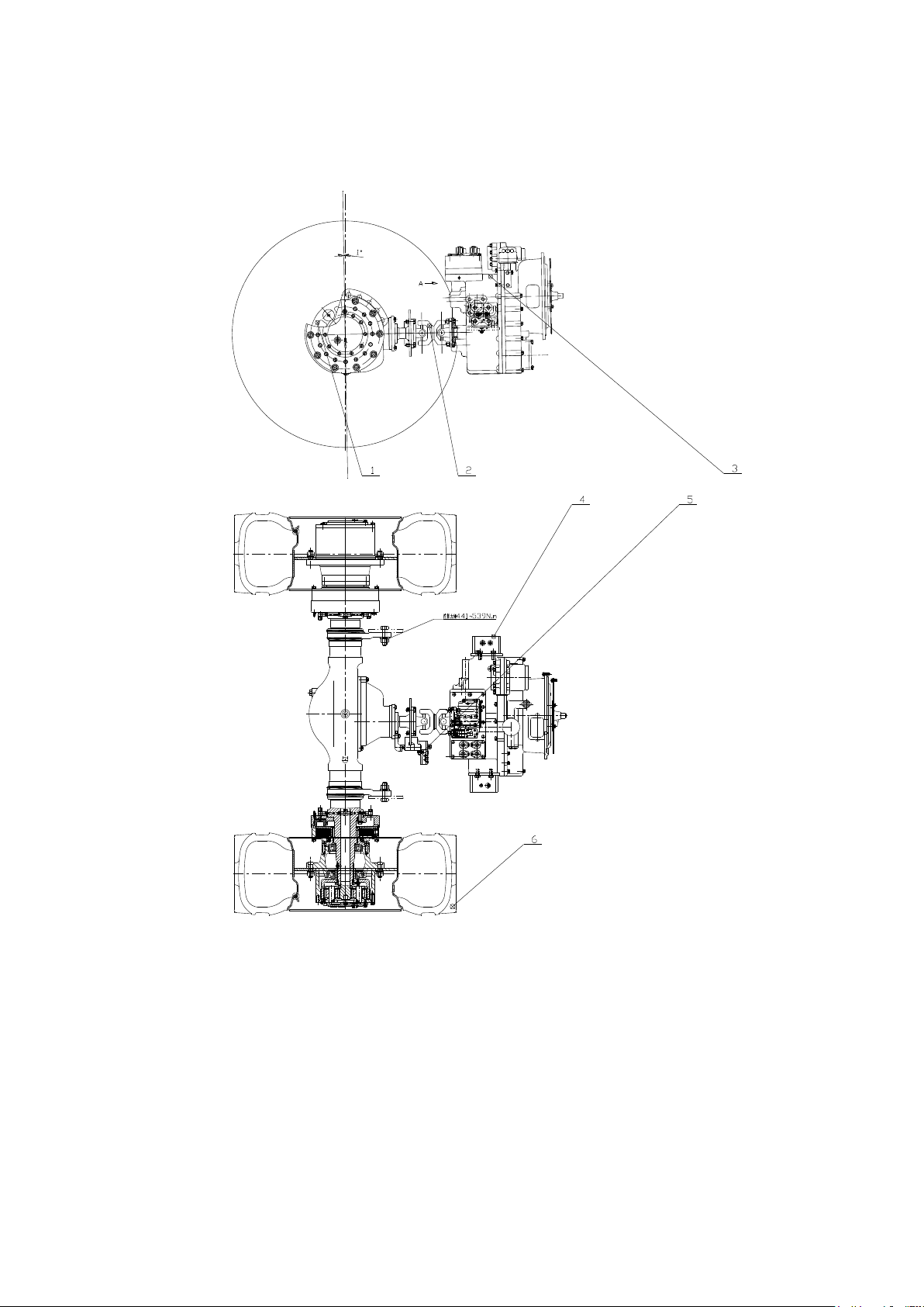
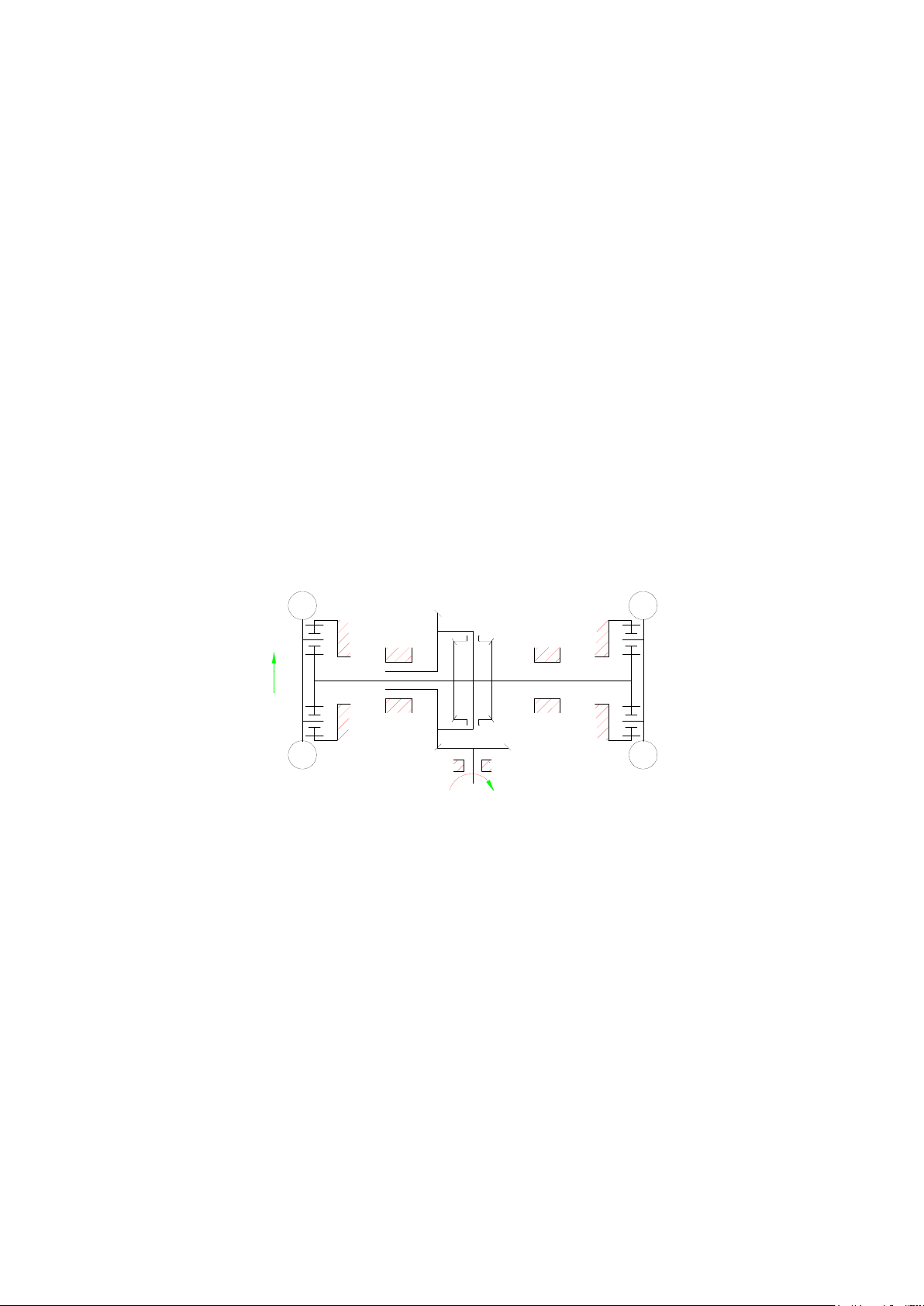
3. Driving axle..................................................................................................................... 6
ⅢSteering system.................................................................................................................. 13
1 Structure introduction ................................................................................................. 13
Ⅳ.Brake system...................................................................................................................... 26
1.Data............................................................................................................................... 26
2.Fault diagnoses and corrections................................................................................... 27
3.Brake inching pedal adjustment.................................................................................... 29
4.Brake valve and accumulator........................................................................................ 30
5.Hand brake.................................................................................................................... 32
6.Service brake................................................................................................................ 38
7.Hydraulic brake malfunction diagnosis......................................................................... 40
8.Exhaust of air in the hydraulic system.......................................................................... 40
Ⅴ.Hydraulic system ................................................................................................................ 40
1.Oil pump........................................................................................................................ 40
2.Multiple directional control valve................................................................................... 42
3.Rotary type piping filter ................................................................................................. 50
4.One-way governor valve............................................................................................... 50
5.Lifting cylinder............................................................................................................... 50
6.Tilting cylinder ............................................................................................................... 51
7.Air exhaust in hydraulic system .................................................................................... 51
8.Hydraulic system fault diagnosis and corrections......................................................... 52
9.Hydraulic system schematic diagram........................................................................... 53
Ⅵ. Lifting system..................................................................................................................... 54
1.Assemble debugging data ............................................................................................ 55
2.Fault diagnosis and corrections.................................................................................... 56
3.Summary....................................................................................................................... 61
4.Mast dismantle and install adjustment.......................................................................... 62
5.Disassembly and installation of lifting cylinder ............................................................. 67
6.Disassembly and installation of tilting cylinder ............................................................. 68
7.Noticing proceeding of debugging................................................................................ 69
Ⅶ.Electrical system ................................................................................................................ 70
1.Control box assembly.................................................................................................... 70
2.Instrument,sensor and relay ......................................................................................... 71
3.Lighting system............................................................................................................. 74
4.Electrical system diagram............................................................................................. 80

1
Ⅰ. Power System
1.Engine for Forklift
Engine
Parameter
Diesel
QSF3.8t3TC112(Cummins)
Rated power
kw
86
Rated rotate
r/min
2200
Max Torque
N·m/speed r/min
470/1100-1700
Forklift truck
model
LS-RT50
LS-RT50-4

2
Ⅱ.Drive system
1. Summarize
Fig2-1 Drive system(Two-wheel drive)
1.Drive axle
2.Drive ShaftAssembly
3.Hydraulic
transmission
gearbox
4.Gearbox bracket
5.Hand Brake Bracket
6.Tyre Assembly

3
Fig. 2-2 Drive system(Four-wheel drive)
1.Drive axle assembly
2.Drive Shaft
Assembly
3.Hydraulic
transmission gearbox
4.Rear Drive Shaft
Assembly
5.Gearbox bracket
6.Hand Brake Bracket
7Tyre Assembly

4
2.Hydraulic transmission gearbox (four-wheel drive)
1.Summary
4F35 hydraulic transmission gearbox is a new type gearbox for four-wheel drive rough terrain
forklift truck, with total 4 shifts (three forward and one reverse)and PTO interface, and time
sharing four-wheel drive can be realized based on the actual requirement.
Torque converter for 4F35 hydraulic transmission gearbox is comprehensive with signal
stage two phase and three working wheel, thus it owns automatic adaptability of hydraulic
transmission output, which can change its output torque and speed as the change of external
load, and absorb and remove the shock vibration from engine and external load to the drive
system; the adopted electronic-hydraulic shift with inching valve and cushion valve makes
operation simple, easy and smooth starting, and greatly reduces the fatigue strength of the
operation.
Axle disengaging mechanism is controlled by solenoid valve, and conversion between
two-wheel drive and four-wheel drive through hydraulic clutch can be carried out at any time
according to the condition of the road, thereby greatly improves the cross-country capacity of the
forklift
2.Main technical parameters
Product model
4F50
Rated output of matched engine Kw
55~74
Rated speed of matched engine r/min
2200~2400
Direction of rotation(face input end)
Clockwise
Drive ratio on
front axle
F1 gear
3.77
F2 gear
1.737
F3 gear
0.86
R gear
1.737
Drive ratio on
rear axle
F1 gear
4.188
F2 gear
1. 93
F3 gear
0.955
R gear
1.93
PTO transmission ratio
0.7838
Torque converter model
YJH315

5
Work oil temperature of gearbox
L-TSA32GB11120 turbine oil or 6#,
8# hydraulic transmission oil
3.Installment and use notice
3.1 The main oil pressure of gearbox is 1.0-1.3 MPa, and the oil pressure of converter is 0.5-0.7
MPa.
3.2 Normal working oil temperature is 70℃~95℃, maximum working oil temperature should not
exceed 120℃or last over 5 minutes.
3.3 Working oil should keep clean, have no other impurity. Replace oil after being used for 100
hours for the first time, and then replace oil per 1000hours or use after stopping for a long time.
3.4 Check the working oil level in the gearbox after the engine starts for 3 minutes, and the oil
level should be within the dipstick regulated scale.
3.5 When the vehicle need shift, first close inching valve and then shift. When braking, first close
inching valve, and then brake to avoid damage clutch or brake malfunction.
4.Fault reason and corrections
Item
Fault reason and corrections
Efficiency
decline and
over high oil
temperature
1 Friction lining stuck or damage. Check if friction lining has gluing,
uneven contact or warpage;
2 Insufficient torque converter oil supply. Check if oil pump wear or
oil level is in normal position;
3 Bearing failure. Replace bearing;
4 Check if lubricating oil line blocks;
5 Torque converter one-way wheel stuck.
Oil leakage
1 Sealing gasket damage; Replace sealing gasket;
2 Rubber parts age or damage; Replace parts;
3 Parts damage. Replace.
Low clutch
pressure or
over large
swing
1 Low oil level. Check oil level and add oil to normal oil level;
2 Input shaft assembly and piston sealing ring wear or the joint is
wedged when assembling. Replace sealing ring or be careful when
assembling.
3 Oil pump wear; Replace oil pump.
4 Inching valve rod not reset.

6
3.Drive axle
1. Structure and Working Principle
1.1 Structure and Working Principle
The basic structure of the driving axle is shown in Fig. 2-5. It is mainly composed of axle
housing assembly, main drive, half axle, wheel-side reducer and wet multi-disc brake.Its working
principle is shown in Fig. 1. The driving moment is input into the main drive, and the direction of
power is changed by the vertical installation of active bevel gears and driven bevel gears.The
speed is reduced and the transmitted torque is increased. Then the power is transmitted to the
wheel edge through differential and half axle. After further deceleration by the wheel edge
deceleration mechanism, the motion and moment are transmitted to the two driving wheels.
Fig. 1 Working schematic diagram
1.2.Wheel Edge Reducer and Bridge Shell Structure
The wheel side reducer is a planetary deceleration mechanism, mainly composed of
planetary gear frame, internal gear, planetary gear, solar gear, etc. The internal gear is fixed on
the wheel support axle by spline, and the planetary gear frame and hub are fixed in one. Details
are shown in Figure 2, Figure 3 and Detailed Table 1.

7
1.3.Main transmission structure
The main transmission structure is composed of a pair of spiral bevel gears and a differential.
Differential is a differential planetary gear transmission consisting of two conical spur half-axle
gears, four conical Spur Planetary gears, the left and right shells of the differential, the friction
discs of the differential and the cross axle. See Figure 4 and Table 2 for details.
1.4.Structure and Principle of Wet Brake
The structure of wet brake is detailed as shown in Fig. 5 and Table 3. It is mainly composed
of piston cylinder, brake shell, piston, dynamic friction disc, static friction disc, gear ring and
floating seal seat.At a certain pressure, the brake oil enters the tubing to the piston oil chamber
from the oil inlet, and forms a certain working pressure on the piston's ring section, thus pushing
the piston to the left.Because the dynamic friction disc is fixed on the gear ring and moves at
equal angular velocity with the hub, the static disc is fixed on the inner gear ring, and its angular
velocity is zero.Under the action of positive pressure, the dynamic and static friction discs
generate friction between the friction layers due to the relative motion between them, and the
integral of the friction force at each point in the braking radius is the braking moment.Wheel edge
is braked under the action of braking moment. When oil is cut off, the braking moment is relieved
and the wheel edge can run normally.
1.5.Main technical performance parameters
Total transmission
ratio
i=21
Maximum Input
Torque
M主=2500(N.m)
Single Drive axle
Torque
M制=21 (KN.m)
Driving axle load
W1 =18500(Kg)
Total length of single
drive axle
A=2000 (mm)
Rim Installation
Spacing
B=1660 (mm)
Single Drive axle
Weight
Q1=600(Kg)

8
2. Use of Drive axle
2.1 Installation of drive axle
Rim nuts are M22 *1.5, all Rotate to the right, tightening moment is 633N.m. A set of rim nuts
should be coated with 242 Letai glue before tightening, and must be symmetrical and uniform.In
normal use, it is necessary to check whether the nut is loose and tightened in time. The ball end
of the nut should match the rim socket, and make sure that it is contacted and compacted so that
the connection is firm.
2.2 Fueling method of driving axle
First, open the oil face hole bolts on the bridge package and the left and right sides of the
wheel, and make the arrows on the left and right hubs face down. Add the lubricant at the left,
right and middle positions at the same time until the oil face overflows, as shown in the following
figure. (Note: GL-585W/90 heavy-duty vehicle gear oil, standard code GB12895-92 is generally
used.)
2.3 Correct Use of Wet Brake
The working pressure of the brake is 11.8 MPa.Before the main engine moves, please adjust
the foot brake to make the brake flexible and reliable.When debugging, first tighten the deflation
screw (serial number 13) and press the foot brake continuously until it feels hard to step forward.
At this time, press the foot brake firmly, release the air screw (serial number 13) to deflate,
release the air bubbles, then tighten the deflation screw and release the foot brake. Repeat these

9
steps until no bubbles appear.Both left and right brakes are operated according to the above
requirements. (Brake medium is hydraulic fluid)
2.4 Hoisting and storage
2.4.1 When the driving axle is hoisted, it is hoisted through the suspension rope at the
position indicated by the arrow in the figure. If it is shoveled, it will still be shoveled up at the
position indicated by the arrow in the figure. Whether it is lifting or shoveling, it is strictly forbidden
to bump or fall off.
Drive axle is bare package. During transportation, partition should be set between bridge and
bridge to avoid collision. Flange of main reducer should be wrapped with moisture-proof paper to
avoid rust. Vent hole of bridge and oil outlet of brake should be blocked with rubber plug.
2.4.2 Safeguard of Drive Axle
It should be stored in the warehouse, not in the open field. The driving axle should be stored
for no more than one year, otherwise the vulnerable parts should be replaced.
3. Common troubleshooting methods of driving axle
Serial
numb
er
Fault
characteristics
Reason
Exclude
1
Sometimes there
are abnormal
sounds at work.
1、Parts friction
2、Poor meshing of
gears
3、Poor lubrication
1、Dismantling, overhauling
or replacing parts
2、Reassembly adjustment
3、Improving Lubrication

10
2
Oil leakage
1、Oil Seal Burning
Aging
2、Bolt loosening
3、Poor lubrication
4、Excessive oil level
5、Wear or insufficient
pressure of floating
ring
1、Replacement of Oil Seal
Slip
2、Tighten bolts
3、Improving Lubrication
4、Delivery of oil to
specified position
5、Replacement of floating
ring or adjustment of
pressure of floating ring
3
Driving axle
temperature is too
high
1、Poor lubrication
2、Improper assembly
of gears and
bearings
1、Improving Lubrication
2、Adjustment according to
drawing requirements
4
Brake lock
1、Brake piston stuck
2、There is a problem
with brake return
circuit
3、Axial movement of
dynamic and static
friction discs is not
effective or stuck
1、Cleaning Brake Cavity
and Piston
2、Check brake return
circuit
3、Check whether there is
any debris or bump on
the surface of the jointed
teeth and repair it.
4. Regular technical maintenance
4.1Level 1 Technical Maintenance (about 50 hours)
4.1.1 If a new car is running in, replace the gear oil. (Note: When changing oil, first start
heating, then drain oil, and then rinse with kerosene. Then, refuel to the designated position.)
4.1.2 Check the movement of each transmission, and do not have abnormal sound.
Check whether the external fasteners of wheel edge, main drive and wet brake are loose and
tightened, and tightening moment according to Table 5.
Serial
number
Specifications
Tightening Torque
(Unit: N.m)
Remarks
3
M12×1.25×114
125
Differential shell bolts (Fig. 3)
45
M24×1.5
1040
Locking nuts (Fig. 3)
12
M16×95
283
Bearing cap bolts (Fig. 3)
15
M14×1.5×40
134
Pelvic Tooth Connecting Bolts
(Fig. 3)
32
M12×70/50
78
Bearing sleeve connecting bolts
(Fig. 3)

11
8
M12×35/60
78
Bracket bolts (Fig. 2)
42
M14×1.5×40
134
Ring retaining bolts (Fig. 2)
30
M14×1.5×45
134
Fixed bolts for planetary frame
(Fig. 2)
13
M10×25
50
End Cover Fixed Bolts (Fig. 2)
9
M12×1.5×100
85
Brake housing connecting bolts
(Fig. 4)
4.1.3 Check the oil leakage situation in each part and repair and remove it in time. All seals
shall not be reused once disassembled.
4.2 Secondary Technical Maintenance (about 1200 hours)
4.2.1 Check and adjust clearance of bearing and pelvic angle teeth according to 3.3.2
requirements.
4.2.2 Change gear oil according to season or overhaul requirements. When changing oil, first
drive to heat, then drain oil, then wash with kerosene, and then refuel to the prescribed position.
4.2.3 Check to clean oil, dirt and dust, especially air plug on front and rear axle housing to
keep unblocked.
4.2.4 Check and fasten external fasteners. If loose, apply Lotai 242 anti-loosening glue, then
tighten.
4.3 Level 3 Technical Maintenance (about 2400 hours)
4.3.1 The front and rear axle wheel reducer, main drive and brake are disassembled and
inspected to repair and replace damaged parts. When assembling, clean the original sealant with
solvent, then apply SD-314 silica gel after drying.All fastener bolts should also be cleaned, dried,
coated with Lotai 242 anti-loosening glue, then tightened, tightening moment to meet the
requirements of Table 5.
4.3.2 Adjustment of main drive and wheel side deceleration mechanism.
4.3.2.1 Axial clearance of active spiral bevel gear bearings (serial number 38) is 0.06-0.10 mm.
At this time, the gears should rotate flexibly, and the sense of no axial movement should be
propelled by hand. The axial clearance of bearings should be adjusted by gasket (serial number
37).
4.3.2.2 The installation distance of spiral bevel gears must be adjusted to the correct position to
ensure correct meshing marks and clearances.Adjustable nut (serial number 1) to achieve.The
axial clearance of bearings is 0.05-0.10 mm, and the side clearance of active and passive spiral
bevel gears is 0.20-0.35 mm. The meshing marks are checked by coloring method. The correct
marks of driven spiral bevel gears are shown in Fig. 5.Contact spots are not less than 50% along
the direction of tooth height and tooth length. The adjustment method of improper marks is shown
in Table 7.

12
4.3.2.3 The minimum meshing clearance between the half-axle gear and planetary gear of the
differential is 0.1 mm, which is adjusted by the half-axle gear gasket to ensure that after assembly,
the differential can be rotated easily by hand without jamming.
4.3.2.4 Wheel-side reducer gears are repaired and replaced. Contact spots should be checked
by coloring method. The height of teeth should be more than 45% and the length of teeth should
be more than 50%.The hub is installed and rotated by hand, so that the bearing is in the correct
position. The round nut is tightened gradually until the hub can only barely rotate, and then the
round nut is returned to 1/10 circles.At this time, the hub rotates freely and there is no axial
movement and swing. Finally, the protrusion of the locking plate is embedded in the slot of the
round nut, so that the axial clearance is controlled within 0.1 mm.
4.3.2.5 When replacing needles in planetary wheels, all needles must be grouped and matched
so that the difference of diameter in the same group is not more than 0.005mm, the needle
cylinder is 0.003mm, and the radial clearance between needle hobbing, gear bore and pin shaft is
0.02-0.03mm.
4.4Detailed List of Vulnerable Parts (Table 6)
Serial
numbe
r
Code number
Name
Specifications
Numbe
r
Remarks
46
HG4-692-67
oil seal
SG60×90×12
1
Main
reducing
flange
43
PR35·39K·2-3
Heavy
floating oil
seal
2
Brake

13
Driven gear contact area
Adjustment way
Adjustment direction
First reduce the adjusting
shim thickness of the bearing
sleeve, get driving bevel gear
close driven bevel gear, if the
backlash is too small, move
driven bevel gear outward.
First increase the adjusting
shim thickness of the bearing
sleeve, deviate driving bevel
gear from driven bevel gear,
if the backlash is too big,
move driven bevel gear
inward.
Ⅲ.steering system
1 Structural Introduction
The steering system is mainly composed of steering device and steering axle assembly, as
shown in Figure 3-1.
The steering device is mainly composed of steering wheel assembly, steering pipe device,
locking handle, full hydraulic steering gear, etc. See Figure 3-2 for details. The steering string and
steering wheel can be adjusted back and forth with an adjustable angle of 6 degrees to meet the
needs of different drivers.

14
The steering axle assembly is mainly composed of steering axle body, steering knuckle,
steering hub, steering wheel, steering cylinder, etc. See Fig. 3-3 for details.
转向桥总成
转向装置
Fig 3-1 Steering System Diagram
Steering gear
Steering axle
assembly

15
1.1Full hydraulic steering gear
1.1.1 Summary
The hydraulic steering gear is load sensing type. The steering gear is equipped with an LS
port, which is connected to the priority valve, so that the steering load pressure signal of the
steering gear is transmitted to the priority valve through the tubing to control the fuel supply of the
steering gear.
In load-sensing steering system, regardless of the load pressure and speed of steering wheel,
the corresponding flow can be assigned priority according to the requirements of steering oil
circuit to ensure that steering is reliable, sensitive and portable.
In addition to the flow required by the steering system, the remaining part of the output flow
of the oil pump can be used for the working oil pipeline, thus eliminating the power loss caused by
excessive oil supply to the steering oil pipeline and improving the efficiency of the system.
Fig 3-2 Steering Device Structure

16
Fig 3-3 Oil Circuit Principle of Full Hydraulic Steering Device
1.1.2 Notices for Installation and Use
1)When the steering gear is installed, it should be coaxial with the steering column, and
there should be clearance between the axes. After installation, check whether the steering wheel
is flexible. Pipeline installation should follow "P" - multi-way valve Ps port; "T" - hydraulic tank; "A"
- turn to the left chamber of the cylinder; "B" - turn to the right chamber of the cylinder; "Ls" -
multi-way valve Ls port.
2)Oil must be kept clean to prevent stolen goods from sticking to the internal parts of the
steering gear and causing steering failure. Therefore, it is necessary to check the condition of
filter element and oil frequently and replace it when necessary.
3)If the steering gear is found to be heavy or malfunctioning in use, the reasons should be
carefully searched first. The steering wheel should not be hard pulled, and the steering gear
should not be easily dismantled to avoid damage to the parts. It is strictly forbidden for two people
to turn the steering wheel at the same time.
1.1.3 Troubleshooting
Trouble
Cause
Phenomenon
Exclusion method
Oil leakage
Bolt loosening at
joint
Tighten bolts
Damage of Seal Ring
at Joint Surface or
Shaft Neck
Replacement of Seal Ring
Washer damage
Replacement of gaskets
Other manuals for LS-RT50
1
Table of contents
Other LiftSmart Forklift manuals