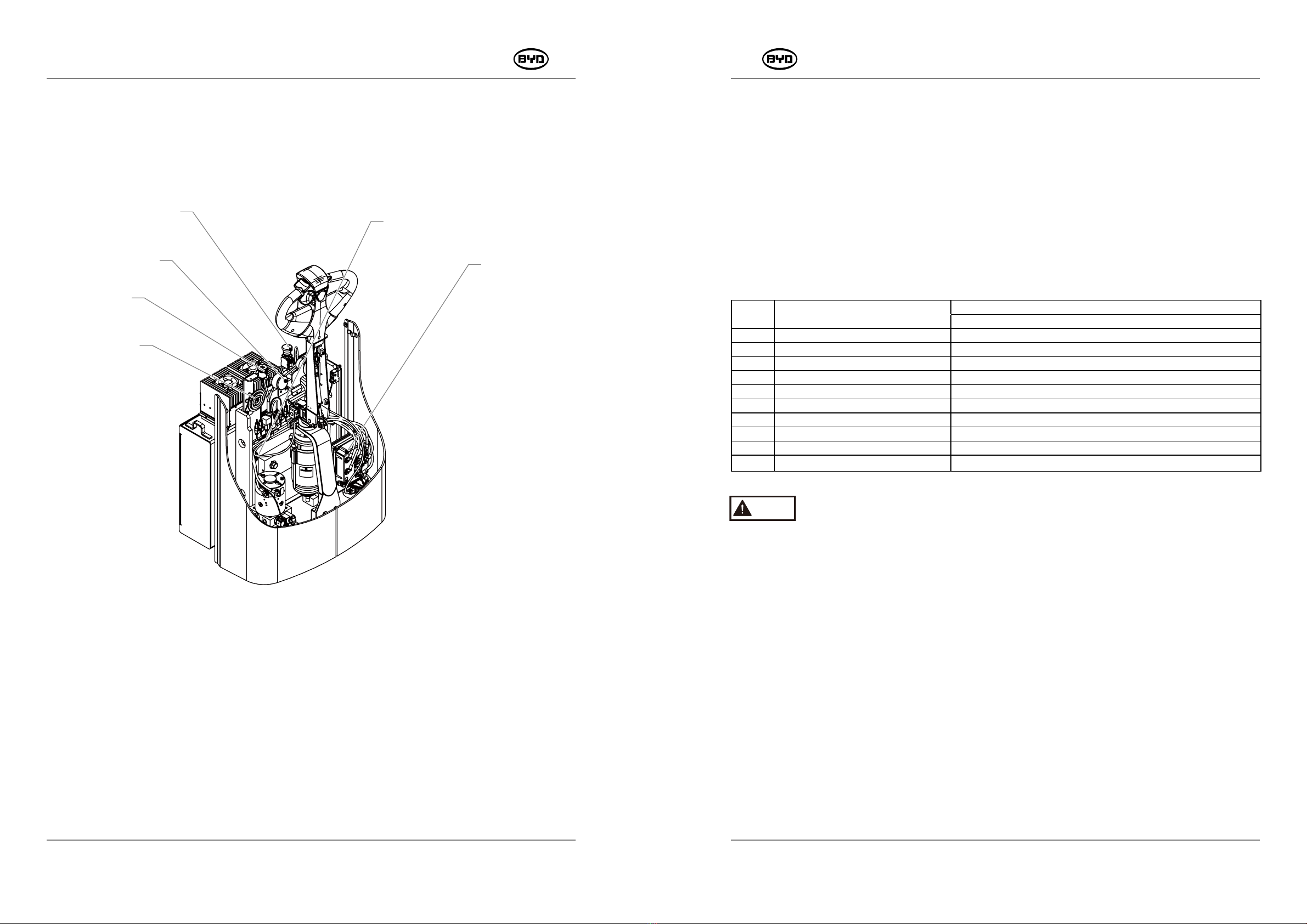
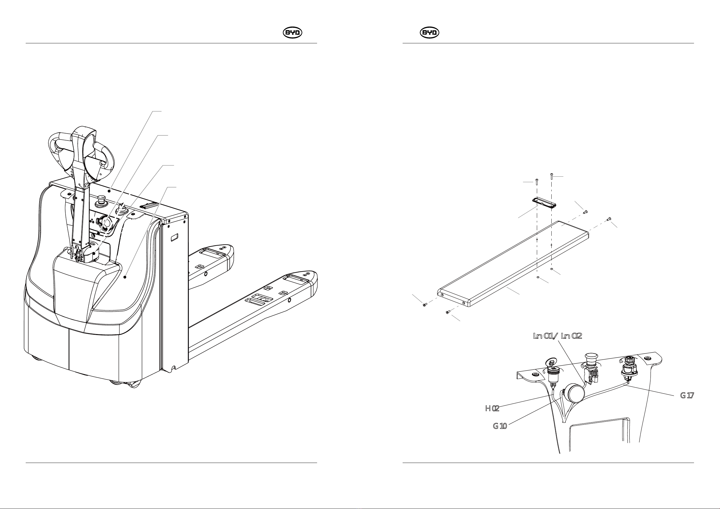
BYD PMW20 User manual

<SM-PMW202020001-EN >
PMW20
SERVICE MANUAL

This manual is applicable to the maintenance of BYD
forklift for authorized personnel.

PMW20
4SM-PMW202020001-EN
PMW20
5
SM-PMW202020001-EN
TABLE OF CONTENTS
INTRODUCTION
1.1 ENTIRE FORKLIFT 8
1.2ATTACHMENTS 9
1.3 CHASSIS 10
1.4 HYDRAULIC DEVICE 11
1.5 ELECTRIC DEVICE 12
DAILY MAINTENANCE
2.1 TIME AND ITEMS 13
2.2 DESCRIPTION 14
REGULAR MAINTENANCE
3.1 TIME AND ITEMS 17
3.2 CATEGORY, DOSAGE AND MODEL OF ACCESSORIES 17
3.3 DESCRIPTION 17
MAINTAIN ATTACHMENTS
4.1 REMOVE AND INSTALL GUARD 19
MAINTAIN CHASSIS
5.1 REMOVE AND INSTALL THE OPERATING HANDLE 22
5.2 REMOVE AND INSTALL THE HANDLE LEVER 24
5.3 REPLACE THE AIR-ACTUATED SPRING 25
5.4 REMOVE AND INSTALL THE STEERING-CONNECTED ASSEMBLY 26
5.5 REMOVE AND INSTALL DRIVE ASSEMBLY 2 7
5.6 SEPARATE DRIVE MOTOR ASSEMBLY FROM REDUCTION GEARBOX
ASSEMBLY
29
5.7 REPLACE DRIVE WHEELS 30
5.8 REPLACE BALANCE WHEELS 31
5.9 REPLACE THE BALANCE MECHANISM 32
5.10 REMOVE AND INSTALL THE ASSISTING SUPPORT ASSEMBLY 36
5.11 REMOVE AND INSTALL THE ASSISTING SUPPORT ASSEMBLY 37
5.12 REMOVE AND INSTALL THE LIFT MECHANISM 38
41
MAINTAIN THE HYDRAULIC DEVICE
4 5
49
54
55
6.1 WORKING PRINCIPLE OF THE HYDRAULIC SYSTEM
6.2 PARTS OF THE HYDRAULIC SYSTEM
6.3 ADD HYDRAULIC OIL
6.4 REMOVE AND INSTALL THE POWER UNIT
6.5 REMOVE AND INSTALL THE POWER UNIT 56
5.13 REMOVE AND INSTALL MAIN BEARING OF COMPOUND ROLLERS

PMW20
6
PMW20
7
8.7 TABLE OF FAULT CODES 122
8.8 ELECTRICAL MAINTENANCE DIAGNOSIS 128
8.9 DESCRIPTION OF ELECTRICAL COMPONENT SYSTEM CONTROL 166
MAINTAIN TUQUE
9.1 CHECK THE TORQUE OF THE KEY FASTENERS 185
APPENDIX
10.1 TABLE OF THE TORQUE VALUE 186
10.2 ONBOARD TOOL 187
10.3 WIRING HARNESS 188
10.4 ELECTRICAL SCHEMATIC DIAGRAM 192
10.5 PARAMETERS OF THE CONTROLLER 196
OTHER INFORMATION 204
6.6 REMOVE AND INSTALL THE LIFT CYLINDER 58
6.7 COMPLETE MAINTENNACE OF THE LIFT CYLINDER 59
MAINTAIN ELECTRIC DEVICE
7.1 ELECTRIC CHECK 62
7.2 CHECK THE MAIN CONTROLLER 60
7.3 REMOVE THE MAIN CONTROLLER 61
7.4 REMOVE THE HORN 66
7.5 REMOVE THE MAIN CONTACTOR 67
7.6 REMOVE THE LIMIT SWITCH 68
TROUBLE SHOOTING
8.1 ELECTRICAL MAINTENANCE DIAGNOSIS 72
8.2 COMPARISON TABLE OF THE DISPLAY ERROR CODES AND
CONTROLLER ERROR CODES
73
8.3 PROGRAM AND SOFTWARE 76
8.4 ADJUST PARAMETERS 97
8.5 MONITOR DATA 105
8.6 BURNING PROCEDURES OF THE SERIAL PORT 112
SM-PMW202020001-EN SM-PMW202020001-EN
OTHER INFORMATION

PMW20
8
PMW20
9
1.1 ENTIRE FORKLIFT
1.2 ATTACHMENTS
INTRODUCTION
Fork
Front
Forklift
Body
Rear
Forkift
Body
Operating
Handle
Assembly
Cover Plate Of The Battery Box
Instrument Panel
Guard Of Tiller
Guard Plate Of The Rear Forklift Body
SM-PMW202020001-EN SM-PMW202020001-EN

PMW20
10
PMW20
11
1.3 CHASSIS 1.4 HYDRAULIC DEVICE
SM-PMW202020001-EN SM-PMW202020001-EN
Steering-Connected Assembly
Welding Assembly of Handle Lever
Operating Handle Assembly
Drive Assembly
Support
Wheel
Assembly
Lift Mechanism
Support Wheel Assembly
Lift Mechanism
Balance Mechanism
Drive Wheel
Balance Mechanism
Cylinder
Hydraulic Power Unit
Cylinder

PMW20
12
PMW20
13
Note
Inspect before each operation.
Hint
Review the last failure before routine inspection.
1.5 ELECTRIC DEVICE
SM-PMW202020001-EN SM-PMW202020001-EN
Controller Assembly
Safety Device
Instrument
Assembly
Emergency Switch
Electric Horn
USB Charging
Connector
DAILY MAINTENANCE
2.1 TIME AND ITEMS
Daily items are inspected daily (or every 8 hours) and weekly (or every 40 hours),
whichever
comes first. For example, if the working hours are less than 8 hours per day, the forklift
shall be inspected daily. If the working hours are more than 8 hours per day, the forklift
shall be inspected every 8 hours.
The list of items to be checked are as follows:
No. Item 1 Day 1 Week
8 Hours 40 Hours
Shape Check
2Wheels Clean and tighten Clean and tighten
3Hydraulic Device Check
4Instrument Check
5Warning Apparatus Check
6Brake Check Check
7Driving, Steering and Operating Check
8Electric Device Check
9Clean Clean
10 Other Abnormalities Check
1

PMW20
14
PMW20
15
2.2 DESCRIPTION
1. Shape
(1) Check whether the forklift is damaged or deformed.
(2) Check whether oil is leaked on the ground where forklifts are put.
(3) Check whether nameplates or signs are complete.
(4) Check whether parts are loose or fall off.
Note
If oil leaks, please identify the position and contact after-sale personnel of BYD.
2. Wheels
(1) Check whether the fastener of wheels is loose. If yes, tighten it.Remove debris
embedded in the tire.
(2) If wheels are worn seriously wherein the wear between left and right wheels are
uneven, or rims are found broken or bent, please replace wheels.
3. Hydraulic Device
Check the device through the level of hydraulic oil.
4. Instrument
(1) Check whether the battery voltage and power on the instrument are displayed
normally.
(2) Check whether a fault indicating lamp appears on the instrument.
5. Warning Device
(1) Press "horn" button and check whether the horn can honk.
(2) Check whether other warning devices are working normally.
6. Brake Performance
Put the handle lever in the brake area and check whether the brake performance is good.
7. Driving, Steering and Checking
(1) Swing the control handle right and left and up and down. Check whether it can rotate
smoothly and make sure no abnormal sound appears in the operation process.
(2) Check whether buttons can work normally.
(3) Check whether fasteners are loose or fall off.
8. Electric Check
(1) Check whether connection terminals of electric device are loose. If any, tighten it.
Check whether joints among the wiring-connected sections are abnormally.
(2) Check whether the safety device of the master controller works normally. If necessary,
replace it.
(3) Check whether the copper bar of the master controller is burned. If
necessary, replace it.
(4) Check whether the low-voltage insurance and relay can work normally. If
necessary,replace them.
SM-PMW202020001-EN SM-PMW202020001-EN

PMW20
16
Warning
Disconnect power before the electric check.
9. Clearance
Clear the entire forklift with compressed air.
10. Other Abnormal Parts
Check whether there are other abnormal parts.
PMW20
17
REGULAR MAINTENANCE
3.1 TIME AND ITEMS
For example, if the service time within 6 weeks are less than 250 hours, the reference
time will be calculated as 6 weeks. Otherwise, 250 hours are preferred. Other reference
time is calculated likewise.
If the operating conditions are relatively poor, the maintenance period should be
shortened and negotiated with the after-sales personnel.
3.2 CATEGORY, DOSAGE AND MODEL OF ACCESSORIES
The amount of accessories is marked with the maximum while the actual amount should
be subject to use.
3.3 DESCRIPTION
1. Hydraulic device
Replace hydraulic oil regularly.
2. Electric device
(1) Check the circuit of the entire forklift.
(2) Check safety device and relay.
(3) Check the main controller.
3. Other Checks
Check the torque of key fasteners.
SM-PMW202020001-EN SM-PMW202020001-EN
Note
Category Item 6(Weeks) 3 6 9 12 Month
250 500 1000 1500 2000 Hour
Hydraulic
Device Replace Hydraulic Oil Replace
Electric
Device Check Electric Device Check
Other
Checks
Check Torque of
Key Fasteners Check
Item Category Dosage Model
Replace
Hydraulic Oil Hydraulic Oil 1L Anti-Wear Hydraulic Oil _Hydraul Ⅰ C-O Ⅰ L-AW46
Note

PMW20
18
PMW20
19
4.1 REMOVE AND INSTALL GUARD
1. REMOVE(Remove the cover plate of the battery box)
1) Remove the guard with the cross screwdriver (Codes13/15/18).
2) Remove the fastener on the battery cover plate with a 4mm Allen wrench (Code 10).
3) Unscrew the instrument assembly on the instrument panel, dual USB charging
connector, self-resetting ignition switch and emergency switch.
4) Unplug the wire harness connectors (H02/G17/Ln01/Ln02/G10).
11
12
13
14
14
13
10
10
10
10
MAINTAIN ATTACHMENTS
This chapter will describe how to maintain attachments.
.
2T2T
-
-
SM-PMW202020001-EN SM-PMW202020001-EN
Cover Plate of the Battery Box
Instrument Panel
Guard of Tiller
Guard Plate of the Rear Forklift Body

PMW20
20
PMW20
21
2. Remove the Guard of the Motor MAINTAIN CHASSIS
This chapter will describe how to maintain chassis.
CODE PART NAME QTY OTHER INFORMATION
10 HEXAGON SOCKET COUNTERSUNK HEAD CAP SCREWS _M6×16 4
11 COVER PLATE OF THE BATTERY BOX 1
12 DOCUMENT CLAMP 1
13 CROSS RECESSED PAN HEAD SCREWS _M4×20 2
14 HEXAGON THIN NUTS 2
15 HEXAGON SOCKET PAN HEAD SCREW_M6×16 5
16 INSTRUMENT PANEL 1
17 GUARD OF TILLER 1
18 CROSS RECESSED PAN HEAD SCREWS _M4×10 2
19 GUARD PLATE OF THE REAR FORKLIFT BODY 1
2. Install
Follow steps in reverse order to install the guard.
15
15
15
15
17
18
19
15
16
18
SM-PMW202020001-EN SM-PMW202020001-EN
Operating Handle Assembly
Welding Assembly Of Handle Lever
Steering-Connected Assembly
Drive Assembly
Support Wheel Assembly
Lift Mechanism
Lift Mechanism
Balance Mechanism
Drive Wheel
Balance
Mechanism

PMW20
23
PMW20
22
5.1 REMOVE AND INSTALL THE OPERATING HANDLE
1. Remove
(1) Unscrew the screw (Code 11) on the controlling handle with a 5mm Allen wrench and
then open the upper and lower covers on the controlling handle.
(2) Remove the screw (Code 11) connecting the handle and aluminium casting witha
5mm Allen wrench and then unplug the data cable G05 (Code 13).
(3) Unscrew the screw (Code 14) on the handle connection block with a 5mm Allen
wrench and then remove the controlling handle.
16
14
14 14
14
15
15 11
11
11
12
13
CODE PART NAME QTY OTHER INFORMATION
11 HEXAGON SOCKET HEAD CAP SCREWS M6×10 3
12 OPERATING HANDLE ASSEMBLY 1
13 DATA CABLE 1
14 HEXAGON SOCKET HEAD CAP SCREWS M6×30 4
15 HEXAGON SOCKET FLAT ROUND HEAD SCREWS M8×15 2
16 ALUMINUM CASTING CONNECTING TO THE HANDLE 1
2. Install
1) Install the screw (Code 14) connecting the handle and aluminium casting.
2) Connect the screw (Code 15) on the lower cover and then plug the data cable (Code 13).
3) Tighten the screw (Code 11) after the upper and lower covers are closed.
4) After installation, start the key and then check whether all buttons are normal.
10
11
12
12
12
12
13
13
14
14
15
16
17
18
19
20
21
22
23
24
24
24
25
26
26
27
27
28 28
28 28
29
30
30
31
32
33
CODE PART NAME QTY OTHER INFORMATION
10 OPERATING HANDLE ASSEMBLY 1
11 COVER OF THE HORN 1
12 SPRING 1 FOR THE HORN SWITCH 1 4
13 SPRING FOR ANTI-COLLISION SWITCH 2
14 PIN BUSHING 2
15 HANDLE PIN 1
16 SHIM 2
17 HEXAGON SOCKET HEAD CAP SCREWS M3×16 2
18 TORISPHERICAL BUTTON (LEFT) 1
19 TORISPHERICAL BUTTON (RIGHT) 1
20 HINGE SPRING (LEFT) 1
21 HINGE SPRING (RIGHT) 1
22 UPPER COVER 1
23 COVER OF THE SPEED REDUCTION SWITCH 1
24 HEXAGON SOCKET HEAD CAP SCREWS M6×10 3
25 LOWER COVER 1
26 HINGE SPRING 2
27 ROCKER OF THE SENSOR 2
28 MAGNET 4
29 COMMUNICATION CIRCUIT BOARD 1
30 MAGNETIC FIXED ROCKER 2
31 LEFT ROCKER 1
32 RIGHT ROCKER 1
33 OVER OF THE ANTI-COLLISION SWITCH 1
Wear antistatic gloves when removing and installing circuit boards.
OPERATING
HANDLE PARTS
SM-PMW202020001-EN SM-PMW202020001-EN
Note

PMW20
25
PMW20
24
12
10
11
5.2 REMOVE AND INSTALL THE HANDLE LEVER
1. Remove
1) Remove the guard. Refer to 4.1 REMOVE AND INSTALL GUARD for details.
2) Remove the bolt (Code 10) with a 8mm open-end wrench or socket wrench and
then tap out the handle axle assembly (Code 11).
3) Remove the bolt (Code 12) on the air-actuated spring with a 13mm wrench and
then unplug the data cable connector.
CODE PART NAME QTY OTHER INFORMATION
10 HEXAGON FLANGE BOLT _M6×10 1
11 HANDLE AXLE ASSEMBLY 1
12 HEXAGON FLANGE BOLT _M8×25 1
2.Install
1) Plug the data cable and then install the handle axle assembly (Code 11).
2) Tighten the screw (Code 10).
3) Keep the handle vertical and then install the lower end of the air-actuated spring .
Tighten the bolt (Code 12).
4) After installation, check whether the handle can rotate freely.
5.3 REPLACE THE AIR-ACTUATED SPRING
1. Remove
1) Open the rear cover of the handle lever and remove the screw (Code 10) with a 3mm
Allen wrench.
2) Remove the bolt (Code 14) on the air-actuated spring with a 10mm open-end wrench.
3) Remove the air-actuated spring.
15
15
13
14
10
10
10
11
10
16
12
CODE PART NAME QTY OTHER INFORMATION
10 HEXAGON SOCKET COUNTERSUNK HEAD CAP SCREWS _M5×12 4
11 1
12 1
13 1
14 1
15 2
16 1
2. Install
1) Install the bolt (Code 14) on the air-actuated spring.
2) Tighten the screw (Code 10) after the upper and lower covers are closed.
3) Install the socket under the lower end of the air-actuated spring. Refer to 5.2.2.3 for
details.
4) Check the air-actuated spring after installation (Press the handle down and check
whether it springs when released).
SM-PMW202020001-EN SM-PMW202020001-EN
REAR COVER OF THE HANDLE LEVER
AIR-ACTUATED SPRING
WELDING ASSEMBLY OF HANDLE LEVER
HEXAGON FLANGE BOLT_M8×25
CROSS RECESSED PAN HEAD SCREWS _M3×10
LIMIT SWITCH ON THE HANDLE

PMW20
27
PMW20
5.4 REMOVE AND INSTALL THE STEERING-CONNECTED ASSEMBLY
1. Remove
1) Remove the handle lever. Refer to REMOVE AND INSTALL THE HANDLE LEVER for
details.
2) Unscrew the screw (Code 11) with a 6mm Allen wrench and remove the steering
connection assembly.
3) Remove the parts of the steering-connected assembly.
CODE PART NAME QTY OTHER INFORMATION
10 STEERING-CONNECTED ASSEMBLY 1
11 HEXAGON SOCKET HEAD CAP SCREWS _M8×35 4
12 HEAVY TYPE SPRING WASHERS 4
13 HEXAGON SOCKET HEAD CAP SCREWS _M5×10 2
14 HANDLE LIMIT MOUNTING BLOCK 1
15 HANDLE LIMIT CUSHIONING PAD 1
16 CROSS RECESSED PAN HEAD SCREWS _M4×10 1
17 BUSHING 2
2. Install
1)Install the parts of the steering-connected assembly first and then install the bushing
Code 17) , handle limit cushioning pad (Code 15) and the handle limit mounting block
(Code 14).
2)2After the position of holes is adjusted, tighten the screw (Code 11) and heavy type
spring washer (Code 12).
26
12
12
11
11
11
11
10
17
17
16
15
13
13
14
5.5 REMOVE AND INSTALL DRIVE ASSEMBLY
1. Remove
(1)Open the guard first and then remove the steering handle assembly.
(2)Disconnect the power line (U/V/W) on the drive motor and unplug the connectors on
on the G32 drive motor temperature sensor and G07 drive motor encoder and G08
motor brake.
(3)Remove the fastener (Code 11) of the drive assembly with a 21mm socket wrench
and lift the drive assembly.
(4)Place the drive assembly on the firm ground or tray.
11
11
10 11
SM-PMW202020001-EN SM-PMW202020001-EN
CODE PART NAME QTY OTHER INFORMATION
10 1
11 4
FASTENER OF THE DRIVE ASSEMBLY
HEXAGON FLANGE BOLT _M16×35

PMW20
29
PMW20
28
2.Install
1) Lift the drive axle into the mounting position.
2) Tighten the bolt (Code 11) on the drive axle.
3) Connect the power lines (U/V/W) on the drive motor.
4) Plug the connectors on the G32 drive motor temperature sensor and G07 drive
motor encoder and G08 motor brake.
G08 Motor Brake
G32 Drive Motor Temperature Sensor
G07 Drive Motor Encoder
Note
Lift the heavy drive assembly with the lifting tool.
5.6 SEPARATE DRIVE MOTOR ASSEMBLY FROM REDUCTION GEARBOX
ASSEMBLY
1.Remove the motor
Remove the bolt (Code 19) for the pivotal bearing of the motor and reduction gearbox with
a 6mm Allen wrench and then take the motor and seal ring down.
2.Remove the Reduction Gearbox Assembly
1) Remove the bolt (Code 14) for the pivotal bearing of the reduction gearbox and reduction
gearbox with a 6mm Allen wrench.
2) Remove the bolt (Code 14) for the pivotal bearing of the reduction gearbox and the
bracket of the reduction gearbox with a 6mm Allen wrench.
12
11
10
19
13
14
15
16
14
17
18

PMW20
31
PMW20
30
1) Lift the rear of the forklift with a jack ,make it has room to operate, and then fill up a
solid piece of wood.
2) Unscrew the nut (Code 11) with the adjustable wrench and replace the drive wheels.
CODE PART NAME QTY OTHER INFORMATION
11 5 90 N-m
12 5
11
12
CODE PART NAME QTY OTHER INFORMATION
10 1
11 1
12 1
13 1
14 24
15 1
16 1
17 1
18 1
19 HEXAGON SOCKET HEAD CAP SCREWS M8X175 4
2.Install
1) Install the pivotal bearing of the reduction gearbox and the bracket of the reduction
gearbox. After the position of holes is adjusted, tighten the bolt (Code 14)
symmetrically.
2) Install the bolt (Code 14) for the pivotal bearing of the reduction gearbox and the
bracket of the reduction gearbox and tighten it.
3) Install the pivotal bearings of the motor and reduction gearbox. Install the seal ring
(Code 17) and then tighten the bolt (Code 19).
5.8 REPLACE BALANCE WHEELS
1) Lift the rear of the forklift with a jack ,make it has room to operate, and then fill up a
solid piece of wood.
2) Unscrew the nut (Code 10) with a 18mm open-end or socket wrench and take out
the bolt (Code 11) and the bushing (Code 12). Then replace the balance wheels.
3) Replace the balance wheel on the other side in the same way.
11
10
12
12
13
CODE PART NAME QTY OTHER INFORMATION
10 1
11 HEXAGON BOLT _M12X90 1
12 MOUNTING BUSHING ON THE BALANCE WHEEL 2
13 BALANCE WHEEL ASSEMBLY 1
SM-PMW202020001-EN SM-PMW202020001-EN
MOTOR
LEVEL-ONE REDUCTION PINION
LOCK NUT
ENCODER
HEXAGON SOCKET HEAD CAP BOLTS M8X25
REDUCTION GEARBOX
TURNING BEARING OF THE REDUCTION GEARBOX
NITRILE RUBBER
FIXED SUPPORT OF THE REDUCTION GEARBOX
HEXAGON FLANGE NUT
SPHERICAL RESILIENT CUSHION
TYPE 1 NON-METALLIC INSERT, HEXAGON LOCK NUT
5.7 REPLACE DRIVE WHEELS

PMW20
32
PMW20
33
18
18
19
A
14
16
16
17
12
12
11
10
15
13
21
17
23
22
22
16
24
25
A
5.9 REPLACE THE BALANCE MECHANISM
5.9.1 Replace the Balance Wheel (Refer to 5.9.2 for details)
5.9.2 Adjustable Balance wheels
1. Remove
1) Remove the bolt (Code 12) with a 13mm socket wrench and then remove the balance
wheel assembly.
2) Remove the circlips for shaft (Code 13) with the circlip plier. Remove the bearing
support of the assisting wheels (Code 11) and then turn it over. Remove the circlips for
hole (Code 15) and then take out the bearing (Code 14).
3) Remove the turning fork assembly (Code 19) and limit fork assembly (Code 25).
Unscrew the nut (Code 16) with a 18mm wrench.
4) Remove the limit fork assembly (Code 25) and the balance wheel assembly (Code
23). Unscrew the nut (Code 16) with a 18mm wrench.
26
19
25
SM-PMW202020001-EN SM-PMW202020001-EN
CODE PART NAME QTY OTHER INFORMATION
10 BACKING PLATE OF THE BALANCE WHEELS 1
11 BEARING SUPPORT OF THE ASSISTING WHEELS 1
12 HEXAGON FLANGE BOLT _M10×25 4
13 CIRCLIPS FOR SHAFT 1
14 DOUBLE ROW ANGULAR CONTACT BALL BEARING WITH SEALING
RING ON BOTH SIDES -3206A-2RS
1
15 CIRCLIPS FOR HOLE 1
16 TYPE 1 NON-METALLIC INSERT, HEXAGON LOCK NUT _M12 3
17 WIDTH LIMIT SLEEVE FOR TURNING SUPPORT OF ASSISTING WHEELS 2
18 HEXAGON-HEADED BOLT_M12×110 2
19 TURNING FORK ASSEMBLY OF ASSISTING WHEELS 1
21 HEXAGON-HEADED BOLT _M12×90 1
22 MOUNTING BUSHING ON THE BALANCE WHEEL 2
23 BALANCE WHEEL ASSEMBLY 1
24 BUFFER SPRING OF ASSISTING WHEELS 1
25 LIMIT FORK ASSEMBLY OF ASSISTING WHEELS 1

PMW20
34
PMW20
35
3. Adjustment Standard for Assisting Wheels
The lowest positions of the drive wheel and the assisting wheels on both sides are on the
same horizontal level.
Assisting tool: spirit level.
Horizontal
Line
Adjustable Bolt
H
CODE PART NAME QTY OTHER INFORMATION
19 TURNING FORK ASSEMBLY OF ASSISTING WHEELS --- ADJUSTABLE 1
25 TURNING FORK ASSEMBLY OF ASSISTING WHEELS ---- ADJUSTABLE 1
26 HEXAGON SOCKET FLAT ROUND HEAD SCREWS _M16×75 1
Note
Before removing the adjustable balance wheels, remove the screws (Code 26).
2. Install
When screwing the bolt to
the right, the height H will
decrease.
Instead, when screwing to
the left, the height H will
increase.
SM-PMW202020001-EN SM-PMW202020001-EN
1) Install the bushing and then tighten the nut (Code 16). Install the the limit fork
assembly (Code 25) and the balance wheel assembly (Code 23).
2) Install the turning fork assembly (Code 19) and limit fork assembly (Code 25). Then
tighten the nut (Code 16).
3) Install the bearing (Code 14) and the bearing support (Code 11). Then install the
circlips for hole.
4) Install the (Code 11) and the turning fork assembly (Code 19). Then install the the
circlips for shaft (Code 13).

PMW20
36
PMW20
37
5.10 REMOVE AND INSTALL THE ASSISTING SUPPORT ASSEMBLY
1. Remove
1) Lift the rear of the forklift with a jack, Unscrew the bolt (Code 13) and remove the
assisting support plate.
2) Then unscrew the bolt (Code 11) and remove the assisting mounting plate.
3) Replace the assisting support assembly on the other side in the same way.
13
12 11
13
10
11
2 Install
When the assisting support plate (Code 12) is worn, adjust the holes on the support plate
downwards in turn.
5.11 REMOVE AND INSTALL THE ASSISTING SUPPORT ASSEMBLY
1) Lift the front end of the fork ,fill up a solid piece of wood,press the emergency stop
switch.
2) Unscrew the screw (Code 10) with a 13mm open-end wrench and then unscrew
the screw (Code 11) with a 4mm Allen wrench. Tap out the mounting shaft for the
support wheel with a copper rod (Code 12) and then replace the support wheel
assembly (Code 13).
3) Replace the support wheel assembly of the other side of the fork.
13
12
11
10
SM-PMW202020001-EN SM-PMW202020001-EN
CODE PART NAME QTY OTHER INFORMATION
10 ASSISTING MOUNTING PLATE 1
11 HEXAGON FLANGE BOLT _M10×20 4
12 ASSISTING SUPPORT PLATE 1
13 HEXAGON FLANGE BOLT _M10×25 2
CODE PART NAME QTY OTHER INFORMATION
10 TYPE 1 HEXAGON NUT _M8 1
11 HEXAGON SOCKET SET SCREW_M8×20 1
12 MOUNTING SHAFT FOR SUPPORT WHEELS -Φ25×144 1
13 SUPPORT WHEEL ASSEMBLY -Φ82×110 1
1)Install the assisting mounting plate first and then tighten the bolt (Code 11).
2)Install the assisting support plate and tighten the bolt (Code 13).
Note

PMW20
38
PMW20
39
5.12 REMOVE AND INSTALL THE LIFT MECHANISM
1. Remove
1) Tap out the pin (Code 11) and the rotation shaft (Code 10) with an appropriate tool.
2) Unscrew the nut (Code 14) with a 13mm open-end wrench.
3) Unscrew the screw (Code 13) with a 4mm Allen wrench and then tap out the rotation
shaft (Code 12) for removing the lift mechanism.
13 14
11
10
12
2. Install
1) Place the lift mechanism into the installation position.
Hammer into the the rotation shafts (Code 10 and Code 12) with the copper bar.
2) Hammer into the pin (Code 11).
3) Tighten the screw (Code 13) and the nut (Code 14).
Note
If the the pull rod has been removed or the nut is loose, adjust the height of the fork
timely and then tighten the nut.
3. Adjust the Height After Installation
Adjustment standard: The minimum height H is 82 ~ 83mm.
H
Obey the following steps to adjust the minimum height of the fork:
1) Tighten the nut 1 and leave enough room to adjust the nut 2.
2) Unscrew the nut 3 and then adjust the nut 2 until the fork reaches the height set.
3) Tighten the loose nut 3.
4) Tighten the nut 1.
When screwing the nut to the right, the height H will decrease.
Instead, when screwing to the left, the height H will increase.
SM-PMW202020001-EN SM-PMW202020001-EN
CODE PART NAME QTY OTHER INFORMATION
10 ROTATION SHAFT OF THE SUPPORT WHEEL ARM 1
11 ELASTIC ROUND PIN 1
12 ROTATION SHAFT OF THE CONNECTION LEVER -190×550 1
13 HEXAGON SOCKET SET SCREW 1
14 HEXAGON FLANGE NUT_M8 1
Table of contents
Other BYD Forklift manuals
Popular Forklift manuals by other brands

Hyundai
Hyundai 160D-9L manual

Presto Lifts
Presto Lifts Power Stak PPS2200-150AS Installation, operation and service manual

Ravas
Ravas 100 Series owner's manual

Still
Still RX60 25-35 Original instructions

Manitou
Manitou MLA 628 -120 LSU 3-E2 Series Operator's manual

Hyster
Hyster B262 Service & repair manual