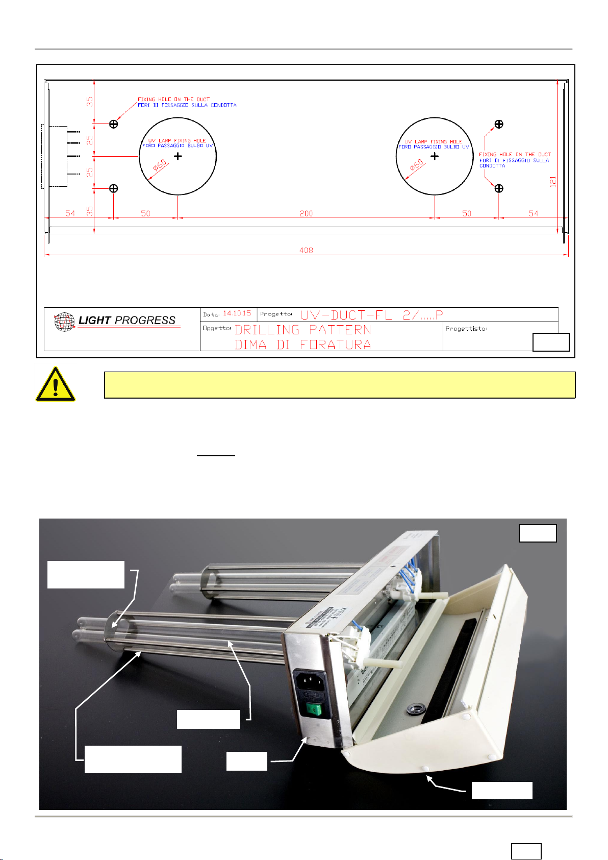
LIGHT PROGRESS DUCT-FL [eng]
apr-2020 Pag. 2/16
SECURITY WARNINGS
The Company has ensured that every care is taken in the design and production of its machinery. In order to guar-
antee, as far as possible, that it is safe when used correctly. However, the laws on accident prevention require all users
of the machinery to ensure that whoever is responsible for installation, maintenance, use and sale of these products is
shown the instruction provided by our company and is made aware of the precautions to be taken.
According to the circumstances, the appropriate recommendations made in these instructions must be made available,
together with any other relative information, to any company or person involved in the installation of LIGHT PRO-
GRESS products.
Only use this appliance for its intended purpose as described in this booklet.
If the appliance is wrongly operated for a purpose other than that for which it is intended, no liability can be accept-
ed for any possible damage. The manufacturer cannot be responsible for any damage to people, animals and objects
caused by use or operation of the appliance contrary to these instructions.
As with all electrical appliances the safety information and precautions contained in this booklet must be carefully
observed, including following:
Before maintenance or cleaning ensure that the appliance is switched off and unplugged from the mains supply.
Should the appliance become faulty please contact our authorized Service Centre direct and in case of repairs ask
for genuine parts.
Improper repairs may damage the appliance and place the user at serious risk.
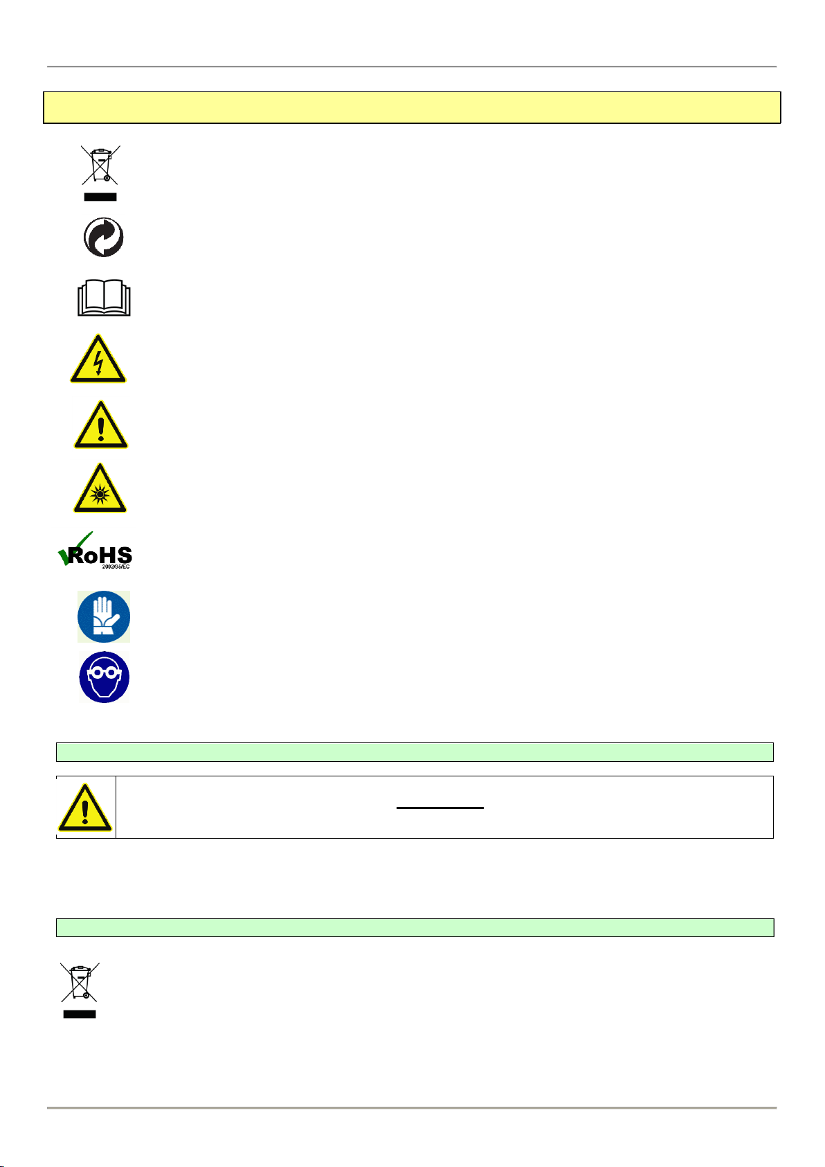
WARNING
Avoid exposition to UV-C rays emitted by the germicidal lamps, even for few sec-
onds, it may cause severe conjunctivitis and erythema
Plastic or painted surfaces exposed to direct uv-c rays may turn yellow with time,
and show an aspect of aging-waving bright as if exposed to sunlight for long
periods.
The intended use is as a germicidal lamp for sterilization, any other use is im-
proper and dangerous
The lamp, as supplied, cannot be modified or designed for use with accessories
or tools
We disclaim all responsibilities and void the warranty in case of tampering or
lack of maintenance
Read carefully the following instruction before use
In case of opening of the UV section, must be provided a shut-off of the UVC devices in
order to avoid exposure to UVC light emitted by the germicidal lamp; It may cause severe
conjunctivitis and erythema.
Remove the protection film from the device before light-on the UV-C lamp.
This device can be used by children with no less than 8 years and by persons with re-
duced physical, sensory or metal capacities or with no experience or knowledge, as long
as under supervision or often they have receiv3ed the related instructions about the safe
use of the device and the related risks. Kids do not have to play with this device.