Lightware LW24 LiDAR User manual

LW24 LiDAR sensor
MicroLiDAR for obstacle detection
Disclaimer
Information found in this document is used entirely at the reader’s own risk and whilst every effort has been made to ensure
its validity, neither LightWare Optoelectronics (Pty) Ltd nor its representatives make any warranties with respect to the
accuracy of the information contained herein.
LW24/C/SI microLiDAR™ sensor - Product guide |Version 0|03 March 2022 Page 1of 36

Table of contents
Overview 5
Product support 5
Specifications 5
Quickstart guide 6
Package contents 11
The LW24/C box includes: 11
Dimensions 12
Components 12
Optical assembly 12
Heatsink & EMI shield 13
Connectors & indicators 14
Communication cable pinout 14
Installation 14
Mounting 14
Operating concepts 16
Distance measuring 16
Serial port baud rate 17
Startup mode 17
I2C address 17
I2C bus speed 17
Update rate 17
Zero distance offset 17
Lost signal threshold 17
Enable median filter 18
Median filter size 18
Enable rolling average filter 18
Rolling average size 18
Enable smoothing filter 18
Smoothing filter strength 18
Firmware change log 18
Upgrading firmware 18
Safety & maintenance 18
Safety overview 18
Laser eye safety 19
Electrical safety 19
Mechanical safety 20
LW24/C/SI microLiDAR™ sensor - Product guide |Version 0 |03 March 2022 Page 2of 36

Service & maintenance 20
Cleaning 20
Serial interface 20
Packets 21
Checksum 22
C/C++ 22
JavaScript 22
Receiving packets 23
Handling request & response 24
I2C interface 24
Overview 24
Command list 26
Command descriptions 27
0. Product name 27
1. Hardware version 27
2. Firmware version 27
3. Serial number 28
7. UTF8 text message 28
9. User data 28
10. Token 28
12. Save parameters 28
14. Reset 28
16. Stage firmware 29
17. Commit firmware 29
27. Distance output 30
30. Stream 30
44. Distance data in cm 31
45. Distance data in mm 31
50. Laser firing 32
57. Temperature 32
66. Update rate 32
74. Noise 33
75. Zero offset 33
76. Lost signal counter 33
79. Baud rate 33
80. I2C address 34
82. Median filter enable 34
83. Median filter size 34
84. Smoothing filter enable 34
85. Smoothing factor 35
LW24/C/SI microLiDAR™ sensor - Product guide |Version 0 |03 March 2022 Page 3of 36

Overview
The LW24/C is an IP67 LiDAR sensor designed for applications where communication interfaces Serial and I2C or RS232
are required. The LW24/C LiDAR sensor uses a time-of-flight system to make very fast, accurate distance and speed
measurements. The LW24/C LiDAR is effective in most weather conditions, even in direct sunlight. The LW24/C is
virtually immune to background light, wind, and noise, making it an ideal sensor to detect unexpected obstacles.
The LW24/C can take up to 388 readings per second and the configurable features and multiple hardware interfaces
make the LW24/C easy to connect with different types of controllers.
Product support
This document supports the following devices:
Product
Hardware
Firmware
Supported
LW24/C/SI
1
2.0.0
Yes
Revision
Date
Notes
0
01/01/2022
Initial release
Specifications
Performance
Range
0.2 … 100 m / 0.6 … 328 ft (white wall in daylight conditions)
Update rate
48 … 388 readings per second
Resolution
1 cm / 0.033 ft
Accuracy
±10 cm / ±0.33 ft
Connections
Power supply voltage
4.5 V … 5.5 V
Power supply current
55 mA typical
Outputs & interfaces
Serial and I2C (3.3 V TTL, 5V tolerant)
Form Factor
Dimensions
35 mm x 47 mm x 38 mm / 1.4” x 1.85” x 1.5”
Weight
28.7 g / 1.01oz (excluding cables)
Enclosure rating
IP67
Optical
Approvals
FDA: 1710193-000 (2020/09)
Laser safety
Class 1M (refer to www. lightware.co.za/safety for full details)
Optical aperture
10 mm
Beam divergence
< 0.5°
Environmental
Operating temperature
-10 ... + 50°C / 14 … 122 °F
LW24/C/SI microLiDAR™ sensor - Product guide |Version 0 |03 March 2022 Page 5of 36

Shipping temperature
- 40 … + 80 °C / - 40 … +176 °F
Accessories
Main cable
Tensility International Corp Straight 4 position female to wire, 1.83 m (DigiKey:
839-1553-ND)
Optional
Tensility International Corp Right-angled 4 position female to wire, 1.83 m (DigiKey:
839-10-03635-ND)
Default settings
Serial port settings
115200 baud, 8 data bits, 1 stop bit, no parity, no handshaking
I2C address
0x66 (Hex), 102 (Dec)
Update rate
48 readings per second
Quickstart guide
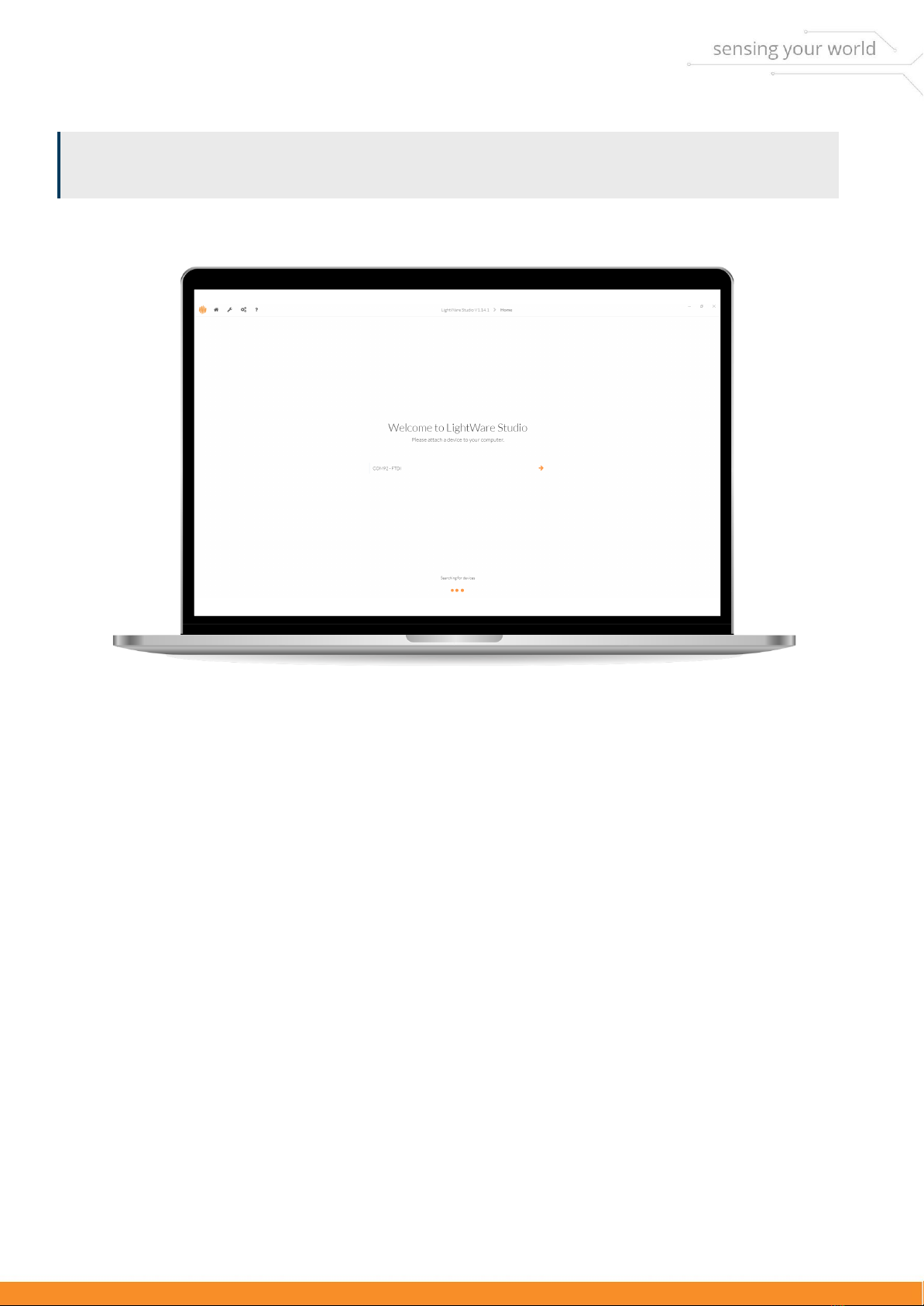
LightWare Studio is an application (available for Windows, macOS, and Linux) that can configure, update, and visualize
data for the LW24/C.
In this guide we will use LightWare Studio to view distance data from the LW24/C.
LightWare Studio can be found here. Download the version compatible with your operating system and proceed with
installation. You can safely install over an existing version of LightWare Studio if you are upgrading.
Insert the communication cable into the LW24/C and a serial to USB adaptor.
You will need a serial to USB adaptor to connect the LW24/C to a computer. Any serial TTL 3.3 V USB adaptor will work,
this guide uses one available from LightWare LLChere.
LW24/C being connected to a cable
LW24/C/SI microLiDAR™ sensor - Product guide |Version 0 |03 March 2022 Page 6of 36

Windows users: Please wait for Windows to install the generic communication driver after connecting the LW24/C for
the first time.
Run LightWare Studio. You will be presented with a home screen that shows devices connected to your computer. Your
USB adaptor will be recognized and displayed here.
LightWare Studio device connection screen
You can register your device by clicking on the Register to receive firmware update notifications banner.
Click on the USB adaptor to establish a connection. From here you can access tools to inspect and configure the
LW24/C.
LW24/C/SI microLiDAR™ sensor - Product guide |Version 0 |03 March 2022 Page 7of 36

LightWare Studio device information screen
Click on the Upgrade tool in the left panel. It is recommended to make sure your LW24/C has the latest firmware. You
can see the changes that have been made to each version, and the option of downgrading is also available. If you
choose to upgrade, then click the Install button and follow the instructions.
LightWare Studio device upgrade screen.
LW24/C/SI microLiDAR™ sensor - Product guide |Version 0 |03 March 2022 Page 8of 36

Click the Distance tool in the left panel. This tool shows you distance readings gathered by the LW24/C. Feel free to
point the LW24/C at various surfaces to measure their distances.
LightWare Studio LW24/C scanning screen.
Parameters are shown in the panel on the top right of theLightWare Studiowindow. Modify these parameters to fit
your application.
LW24/C/SI microLiDAR™ sensor - Product guide |Version 0 |03 March 2022 Page 9of 36

LightWare Studio LW24/C scanning parameters.
For a detailed breakdown on what the parameters do and how they affect the operation of the LW24/C, see
theoperating conceptssection.
What's next?
The next step is to integrate the LW24/C into your platform of choice. Please follow one of the integration guides, or
consult the communication protocol reference for building your own system to interact with the LW24/C.
LW24/C/SI microLiDAR™ sensor - Product guide |Version 0 |03 March 2022 Page 10 of 36

Package contents
The LW24/C box includes:
1 x LW24/C MicroLiDAR unit
1 x Tensility straight DigiKey:
839-1553-ND
Optional:
1 x Tensility 90 degree DigiKey:
839-10-03635-ND
5 x M2 x 12 Pan slotted screw)
5 x M2 hex nut
5 x Flat washer
Hardware
Dimensions
LW24/C dimensions
LW24/C/SI microLiDAR™ sensor - Product guide |Version 0 |03 March 2022 Page 11 of 36

Components
LW24/C view from above and below
Optical assembly
The optical assembly comprises the laser and receiver lenses.
LW24/C optical assembly
Heatsink & EMI shield
The lid lowers EMI radiation entering or leaving the LW24/C. It also acts as a heatsink to draw heat away from the
LW24/C.
LW24/C/SI microLiDAR™ sensor - Product guide |Version 0 |03 March 2022 Page 12 of 36

LW24/C shield
Connectors & indicators
LW24/C connectors & indicators
Communication cable pinout
Pin
Function
Notes
1
+5V
4.5 V … 5.5 V, 55mA I(typical)
2
RXD/SDA
RXD when using Serial, SDA when using I2C.
3
TXD/SCL
TXD when using Serial, SCL when using I2C.
4
GND
Ground
LW24/C/SI microLiDAR™ sensor - Product guide |Version 0 |03 March 2022 Page 13 of 36

Installation
Mounting
Make sure the LW24/C is functional before installation. You can use LightWare Studio to verify operation. See the quick
start with LightWare Studio for details.
The LW24/C requires a clear line-of-sight to measure distance to a target surface. It can be mounted with a vertical or
horizontal lens orientation.
LW24/C mounting orientations
The LW24/C can be mounted in a downward facing orientation for altimetry, terrain following or precision landing
applications. For terrain following, install the rangefinder at an angle to reduce lag time in reaction. The angle depends
on the speed traveled, and the overall system lag, but should be between 20 and 45 degrees. The LW24/C can be
mounted forward facing orientation for sense-and-avoid or position-hold applications.
LW24/C mounting directions
LW24/C/SI microLiDAR™ sensor - Product guide |Version 0 |03 March 2022 Page 14 of 36

Take note:
●Make sure the LW24/C is securely mounted to prevent false readings or damage.
●Allow for proper ventilation.
●Secure the communication cable to prevent it from pulling on the connector.
Ensure that nothing is in the path of the laser beam. Ensure that no shiny or highly reflective surfaces are near the path
of the beam.
Operating concepts
Distance measuring
The LW24/C is a single point distance measuring LiDAR. It uses time of flight technology to determine the distance of a
target at a configurable update rate of 48 Hz to 388 Hz.
The LW24/C can be connected to a host controller with the serial or I2C interface. The serial port (3.3 V logic level, 5 V
tolerant) has a configurable baud rate. The I2C serial bus (3.3 V logic level and 3.3 k pull up resistors, 5 V tolerant) has a
configurable address and is an alternative to the serial port when multiple devices are connected on a common bus.
LightWare Studio showing measurements from the LW24/C
LW24/C/SI microLiDAR™ sensor - Product guide |Version 0 |03 March 2022 Page 15 of 36

Parameters
LW24/C parameters can be adjusted with LightWare Studio or from the platform of your choice through the serial or
I2C communication interfaces.
LightWare Studio parameters screen
Serial port baud rate
Controls the baud rate used by the serial UART interface in kbps.
(The baud rate should be as high as possible to accommodate high measurement update rates.)
Startup mode
Determines the communication behavior of the LW24/C when turned on.
I2C address
The address used to communicate on the I2C bus.
I2C bus speed
The speed of the I2C bus
Update rate
The number of measurements per second. From 48 Hz to 388 Hz.
Zero distance offset
An offset applied to the measured distance value.
LW24/C/SI microLiDAR™ sensor - Product guide |Version 0 |03 March 2022 Page 16 of 36

Lost signal threshold
The number of failed measurements before a loss of signal is reported.
Enable median filter
The median filter is used to disregard short unwanted measurements.
Median filter size
Determines response time of median filter.
Enable rolling average filter
The rolling average filter averages over a specified number of distance measurements.
Rolling average size
The number of distance measurements to use for the rolling average filter.
Enable smoothing filter
The smoothing filter is used to remove noise from the measurements.
Smoothing filter strength
Determines response of the smoothing filter.
Firmware change log
Upgrading firmware
The LW24/C firmware can be upgraded by using LightWare Studio. Download LightWare Studio here.
Follow the Quick start with LightWare Studio guide for details on downloading and using LightWare Studio.
2.0.0
Notes:
●Initial release.
Safety & maintenance
Safety overview
The LW24/C should not be disassembled or modified in any way. The laser eye safety rating depends on the
mechanical integrity of the optics and electronics. There are no user serviceable parts and maintenance, or repair must
only be carried out by the manufacturer or a qualified service agent.
LW24/C/SI microLiDAR™ sensor - Product guide |Version 0 |03 March 2022 Page 17 of 36

Always observe the following safety precautions when operating the LW24/C. Failure to comply with these precautions
or specific warnings given in this product guide violates the safety standards of the intended use for the sensor and
may damage the sensor. LightWare LLC assumes no liability for failure to comply with these requirements.
The LW24/C is not field serviceable. For any repairs, the equipment should be completely isolated, removed then
packaged carefully. Please visit LightWare LLC’srefund policyfor Return Merchandise Authorization (RMA) details, or
contact[email protected].
Laser eye safety
The LW24/C emits ionizing laser radiation. The level of the laser emission is Class 1M which indicates that the laser
beam is safe to look at with the unaided eye, but must not be viewed using binoculars or other optical devices.
Notwithstanding the safety rating, avoid looking into the beam and switch the unit off when working in the area.
The laser eye safety rating depends on the mechanical integrity of the optics and electronics, if these are damaged do
not continue using the LW24/C.
Laser emitting lens
The LW24/C is rated laser Class 1M eye safe. Class 1M laser is safe for all conditions of use however it is not safe to
view the laser through magnifying optics such as microscopes, binoculars, or telescopes.
The use of optical instruments with this product will increase eye hazard.
Class 1M laser radiation label
LW24/C/SI microLiDAR™ sensor - Product guide |Version 0 |03 March 2022 Page 18 of 36

Electrical safety
●Check all electrical connections are isolated and that there are no exposed wires.
●Make sure the power supplied to the device does not exceed the maximum rated voltages which are specified in
the technical specifications section.
●The electrical wiring layout of this device is provided in the hardware section.
Mechanical safety
●Ensure that there is adequate airflow permitted for the sensor.
●The mechanical dimensions for mounting the LW24/C are provided in the hardware overview.
Laser radiation information
Specification
Value/AEL
Notes
Eye safety classification
Class 1M
Laser wavelength
905 nm
Pulse width
16 ns
Pulse frequency
20 kHz
Average power
< 2.5 mW
NOHD
15 m
Distance beyond which binoculars
may be used safely.
Approximate values only. Please contact LightWare LLC if further information is required.
Service & maintenance
The LW24/C is not field serviceable. For any repairs, the equipment should be completely isolated, removed then
packaged carefully. Please visit LightWare LLC’srefund policyfor Return Merchandise Authorization (RMA) details, or
contact[email protected]
Cleaning
Use a dry and clean microfiber cloth to gently wipe across the lenses of the sensor, taking care not to scratch the
surface of the lenses.
LW24/C/SI microLiDAR™ sensor - Product guide |Version 0 |03 March 2022 Page 19 of 36

Serial interface
Overview
We suggest using the pre-built APIs for communicating with the LW24/C where possible.
The LW24/C uses a packet based binary protocol which can be accessed over the serial and I2C interfaces. All
higher-level APIs (C, Python, JavaScript) use this protocol to function.
If you require more control than the existing APIs offer or need to port the protocol to a different platform, then you
can use the information here to build a compatible system.
Communication is performed using encapsulated packets for both sending and receiving data. Every packet that is sent
to the LW24/C is known as a request and a correctly formatted request will always be replied to with a response. There
are cases where the LW24/C will send a request packet to the host, these packets are considered streaming packets as
they arrive without a direct request from the host - they do not require a response from the host.
Streaming data is only available through the Serial interface.
Requests are made using one of the available commands and are either flagged as read or write. When a read request
is issued then the response will contain the requested data. When a write request is issued then the contents of the
response will vary depending on the command.
Default serial interface properties
●Baud rate: 115200
●Data: 8 bit
●Parity: none
●Stop: 1 bit
●Flow control: none
Packets
A packet for both requests and responses is composed of the following bytes:
Header
Payload
Checksum
**Byte:**
Start
Flags Low
Flags High
ID
Data 0 .. N
CRC Low
CRC High
LW24/C/SI microLiDAR™ sensor - Product guide |Version 0 |03 March 2022 Page 20 of 36
Table of contents
Other Lightware Accessories manuals
Popular Accessories manuals by other brands

Sony
Sony AKA-RD1 operating guide

Fiamma
Fiamma F45s Series Maintenance and repairs

Dometic
Dometic 8700 Series MasterFlush Installation and operating manual

Kalamera
Kalamera KRC-70BV Instruction Manual & Operation Guide

Owlet Home
Owlet Home J1 quick start guide

MHS Boilers
MHS Boilers CRUZ belt Installation, operation & maintenance manual