manuals.online logo
Brands
  1. Home
  2. •
  3. Brands
  4. •
  5. Lightware
  6. •
  7. Matrix Switcher
  8. •
  9. Lightware MX2-8X8-HDMI20-AUDIO User manual

Lightware MX2-8X8-HDMI20-AUDIO User manual

Quick Start Guide
MX2-8X8-HDMI20-AUDIO
Further Information
The document is valid with the following rmware version: 1.0.0
The User’s manual of this appliance is available on www.lightware.eu.
See the Downloads section on the website of the product.
Contact Us
[email protected]
+36 1 255 3800
[email protected]
+36 1 255 3810
Lightware Visual Engineering LLC.
Peterdy 15, Budapest H-1071, Hungary
Doc. ver.: 1.0
19200044
Important Safety Instructions
Please read and keep the information in the attached safety instructions supplied with the
product before you start using the device.
Introduction
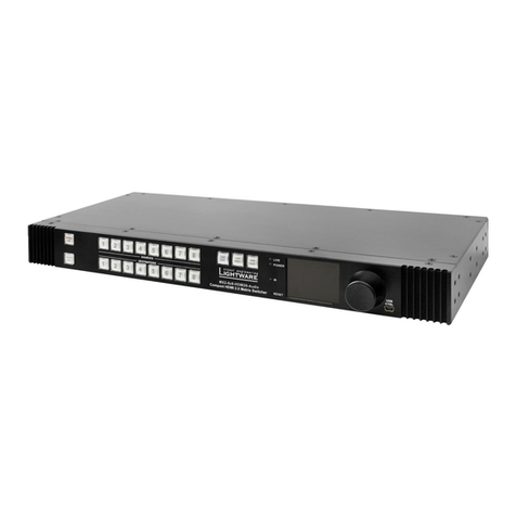
The MX2-8x8-HDMI20-Audio is the rst Lightware HDMI 2.0 standalone matrix router that
supports uncompromised 4K UHD resolution at 60Hz 4:4:4. Thanks to its compact size and
silent design, it is particularly suitable for ofces and meeting rooms, for 4K live events, and
for futureproof operation centers.
Box Contents
Device Concept
The matrix is compatible with the HDMI
2.0 standard. The feature allows to switch
4K x 2K signals with 60Hz and 4:4:4 color
space from any input to any output. Additional analog audio input and output connectors allow
to embed a different audio signal in the HDMI stream or breakout the audio signal from the
HDMI stream on the output.
HDMI 2.0 to 2x HDMI 1.4 Splitting
The device supports vertical splitting of an HDMI 2.0 4k@60Hz 4:4:4 input signal to left and
right halves allowing for the transmission of a 18Gbps HDMI 2.0 signal over two HDMI1.4
compliant links. The two halves can then be recombined at the signal destination. The feature
is demonstrated on the application diagram, see the rear side of this guide.
Analog Audio Options
An external audio signal can be embedded in the HDMI stream by the Analog Audio input
port. In this case the audio from the analog input port is converted and embedded in the HDMI
stream. Furthermore, the Analog audio output ports allow to de-embed the audio of the HDMI
output stream - see the port diagram on the rear side of this guide.

Please note that only stereo LPCM can be de-embedded from the HDMI signal.
HDMI 2.0
Analog
audio
HDMI 2.0
Analog
audio
1
Output Lock Locking one or more outputs.
2
Control Lock Disables or enables front panel operations. Red light means
the switching and function buttons are disabled.
3
Sources Buttons to select an input, to select a preset number or to
view the state of the selected input port.
4
Destinations Buttons to select an output or to see the state of an output.
5
Function Buttons Switching between working modes (Take / Autotake) and
performing Preset operations.
6
Status LEDs Blinking LIVE LED indicates normal operation; POWER
LED is dark in the case of an internal voltage problem.
Front View
7
IR detector LED Reserved for future developments.
8
Reset Button Reboots the matrix (the same as disconnecting from the
power source and reconnecting again).
9
Color Display LCD screen showing the most important settings and
parameters in the front panel menu.
q
Jog Dial Control
Knob
Easy setting and menu navigation by the jog dial control.
Keep dial and click while getting feedback on the LCD.
w
USB Control USB connector for local control functions (e.g. Lightware
Device Controller software).
Rear View
1
AC Connector Standard IEC connector accepting 100-240 V, 50 or 60 Hz.
2
Service Button Hidden button for special operations.
3
RS-232 Port 3-pole Phoenix connector for RS-232 serial port.
4
LAN RJ45 connector to control the matrix via LAN/Ethernet.
5
Input Ports HDMI input ports for sources.
Audio input ports (5-pole Phoenix) for balanced analog
audio input signal.
6
Output Ports HDMI output ports for connecting sink devices.
Audio output ports (5-pole Phoenix) for balanced analog
audio output signal. The signal is de-embedded from the
given HDMI port.
Mounting Options

M4x8 size is the longest allowed screw for xing the ears to the housing. Longer
screw may touch internal parts.
Mounting as a Standard Rack Installation - with front rack ears
Two rack ears are supplied with the product, which
are xed on left and right side as shown in the picture.
The default position allows mounting the device as a
standard rack unit installation.
Under-desk Mounting - with front and rear rack ears

Two rack ears supplied with the product; further
rack ears can be purchased separately.
Please do the following steps:
1. Release and remove the xing screws of both
rack ears on the matrix.
2. Rotate the rack ears by 90° to the desired
direction.
3. Insert the screws into the holes and x the front ears to the matrix.
4. Fix the two other rear ears (not supplied with the product) by the screws on both sides.
5. Fix the matrix by the rack ears to the desired surface (screws not supplied).
Ventilation

To ensure the correct ventilation and avoid overheating let enough free space
around the appliance. Do not cover the appliance, let the ventilation holes free.
The following pictures show the direction of the airow:
Installation
1
Connect the desired source to an HDMI input port.
2
Optionally connect an audio source to the Audio input port which is located next to
the connected HDMI input port.
3
Connect a sink device to an HDMI output port.
4
Optionally connect an audio device (e.g. amplier) to the Phoenix Audio output port
which is located next to the connected HDMI output port.
5
In order to control the matrix via Ethernet, connect the device to a LAN switch/router,
and connect a controller (e.g. Touch panel).
6
Connect the power cord to the AC power socket and to the matrix.

Always use high-quality HDMI cables for connecting sources and displays.
Powering on
Connect the power cord to the AC input connector; the matrix is immediately powered on. After
the self-test (about 20 seconds), the router reloads its last conguration and it is ready to use.

After switching ON, the router reloads the latest settings which had been used before it was
turned off. The router has an internal emergency memory that stores all current settings and
crosspoint states. This memory is independent from the presets and invisible for the user. This
built-in feature helps the system to be ready immediately in the case of a power failure or an
accidental power down.
Software Control – Using Lightware Device Controller (LDC)
The device can be controlled from a computer using the Lightware Device
Controller software. The application is available at www.lightware.eu (Support
/ Downloads section), install it on a Windows PC or a Mac OS X and connect
to the device via LAN, USB or RS-232.
HDMI
cable
1Audio
cable
2
4K PC Media player
HDMI
cable
3
4K projector
Audio amplifier
Touch control
Ethernet
Audio
cable
4CATx
cable
5
Power outlet
6
Power
cable
1
3 4
5
6
2
2 6 7
w8
3 5
4
1q9
MX2-8x8-HDMI20-Audio
Matrix Router
IEC Power Cable LAN Cross-link Cable,
CAT5e type, 3 m length
Phoenix Combicon
3-pole Connector
Safety and Warranty info,
Quick Start Guide
Phoenix Combicon
5-pole Connector (16x)
Safety and
warranty
info
Quick
Start
Guide
Switching Operations
1. First press and release the desired source button.
The pressed source button and all destination buttons
which are currently connected to the source lights up.
SOURCES
DESTINATIONS
2. Press and release the desired destination buttons
which have to be (dis)connected to/from the selected
source. The preselected destination buttons will blink.
SOURCES
DESTINATIONS
3. Press and release Take button; the selected input is
switched to the selected output(s).
Locking an Output
1. Press and release the Output Lock button; it starts to
blink and all the buttons of any locked destinations light
up (view state).
OUTPUT
LOCK
CONTROL
LOCK
2. Press and release a destination button; it starts to
blink (more destinations can be selected sequentially).
OUTPUT
LOCK
CONTROL
LOCK
3. Press and release the Take button. The selected
destinations are now locked.
Switching and Locking Operations in TAKE Mode
Take mode allows the user to connect or disconnect multiple outputs to an input
at once. This mode is useful when time delay is not allowed between multiple
switching. The commands are only realized when the Take button is pressed.
TAKE
AUTO
LOAD
PRESET
SAVE
PRESET
TAKE
AUTO
LOAD
PRESET
SAVE
PRESET
TAKE
AUTO
Control Lock
If the button illuminates in red the switching and function buttons, and the jog dial control knob
are disabled. Press and hold the Control lock button for three seconds to toggle the state.

When the front panel buttons are locked, remote control (RS-232, USB, Ethernet) is still
available.
Typical Application Diagram
Port Diagram
Network Settings
The TCP/IP settings of the matrix are available in the front panel menu. The desired network
parameters can be set as follows:
1. Navigate to the System Settings / Network / DHCP and press the knob to enter.
2. Select the desired option:
a. To get a dynamic IP address set the parameter to Enabled by the jog dial. Press
the knob to store and step back to the previous menu.
b. To get a static IP address set the parameter to Disabled by the jog dial. Press the
knob to set and step back to the previous menu.
3. Select the Save option to apply the new setting; the buzzer will sound.
4. To set the desired static IP address, please do the following steps:
a. Select the Static IP, Static Subnet, and Static Gateway parameters from the
System Settings / Network submenu and press the knob to enter.
b. Use the jog dial to move between the octets, press the knob to edit and use the jog
dial to change the value. Press the knob to store the new value.
c. When all parameters are set select the Save option in the Network menu to apply
changes.
Factory Default Settings
The settings and parameters can be set to factory default via the front panel menu as follows:
1. Navigate to the System Settings / Reset to Factory Defaults submenu and press the
button to enter.
2. Select Yes to conrm the process.
3. The matrix is rebooted and the factory default values are restored - see the attached table.
Factory Default Settings
IP address Dynamic (DHCP is enabled)
RS-232 port setting 57600 BAUD, 8, N, 1
RS-232 port control protocol LW3 protocol
Crosspoint setting Input 1 on all outputs
HDCP mode Auto
Color space / color range Auto / Auto
HDMI mode Auto
Emulated EDID F49 - (Universal HDMI, all audio, deep color support)
EDID memory storage 144 factory / 100 User memory slots
Audio source Embedded audio
Analog audio output Enabled (de-embedded from HDMI signal)
ID Resolution EDID type ID Resolution EDID type
F1 640x480p60.00Hz DVI F22 1920x1200p50.00Hz DVI
F2 848x480p60.00Hz DVI F23 1920x1200p59.56Hz DVI
F3 800x600p60.32Hz DVI F24 2048x1200p59.96Hz DVI
F4 1024x768p60.00Hz DVI F25-F28: Reserved
F5 1280x768p50.00Hz DVI F29 Universal DVI EDID
F6 1280x768p59.94Hz DVI F30 1440x480i60.05Hz HDMI
F7 1280x768p75.00Hz DVI F31 1440x576i50.08Hz HDMI
F8 1360x768p60.02Hz DVI F32 640x480p59.95Hz HDMI
F9 1280x1024p50.00Hz DVI F33 720x480p59.94Hz HDMI
F10 1280x1024p60.02Hz DVI F34 720x576p50.00Hz HDMI
F11 1280x1024p75.02Hz DVI F35 1280x720p50.00Hz HDMI
F12 1400x1050p50.00Hz DVI F36 1280x720p60.00Hz HDMI
F13 1400x1050p60.00Hz DVI F37 1920x1080i50.04Hz HDMI
F14 1400x1050p75.00Hz DVI F38 1920x1080i50.00Hz HDMI
F15 1680x1050p60.00Hz DVI F39 1920x1080i60.05Hz HDMI
F16 1920x1080p50.00Hz DVI F40 1920x1080i60.05Hz HDMI
F17 1920x1080p60.00Hz DVI F41 1920x1080p24.00Hz HDMI
F18 2048x1080p50.00Hz DVI F42 1920x1080p25.00Hz HDMI
F19 2048x1080p60.00Hz DVI F43 1920x1080p30.00Hz HDMI
F20 1600x1200p50.00Hz DVI F44 1920x1080p50.00Hz HDMI
F21 1600x1200p60.00Hz DVI F45 1920x1080p60.00Hz HDMI
F46 1920x1080p60.00Hz HDMI F121 1440x1080p59.91Hz HDMI
F47
Universal; HDMI, PCM audio
F122 2560x2048p59.98Hz HDMI
F48
Universal; HDMI, all audio
F123 1280x800p59.91Hz HDMI
F49
Univ.; HDMI, all audio, deep color
F124 1440x900p59.90Hz HDMI
F50-F97: Reserved F125 1368x768p59.85Hz HDMI
F98 1280x720p60.00Hz HDMI F126 1600x900p59.98Hz HDMI
F99 1920x1080p60.00Hz HDMI F127 2048x1080p60.00Hz HDMI
F100 1024x768p60.00Hz HDMI F128 2560x1080p60.00Hz HDMI
F101 1280x1024p50.00Hz HDMI F129 3440x1440p24.99Hz HDMI
F102 1280x1024p60.02Hz HDMI F130 3440x1440p29.99Hz HDMI
F103 1280x1024p75.02Hz HDMI F131 4096x2160p25.00Hz HDMI
F104 1600x1200p50.00Hz HDMI F132 4096x2160p30.00Hz HDMI
F105 1600x1200p60.00Hz HDMI F133 4096x2160p60.00Hz HDMI
F106 1920x1200p59.56Hz HDMI F134 3440x1440p23.99Hz HDMI
F107 2560x1440p59.95Hz HDMI F135 4096x2160p24.00Hz HDMI
F108 2560x1600p59.86Hz HDMI F136 3840x2400p29.99Hz HDMI
F109 3840x2400p24.00Hz HDMI F137 3840x2160p60.00Hz HDMI 2.0
F110 3840x2160p24.00Hz HDMI F138 3840x2160p50.00Hz HDMI 2.0
F111 3840x2160p25.00Hz HDMI F139
Univ.; HDMI 2.0, UHD, PCM audio
F112 3840x2160p30.00Hz HDMI F140
Univ.; HDMI 2.0, UHD, all audio
F113-F117: Reserved F141 4096x2160p60.00Hz HDMI 2.0
F118
Universal; HDMI, 4K, PCM audio
F142 4096x2160p50.00Hz HDMI 2.0
F119
Universal; HDMI, 4K, all audio
F143
Univ.; HDMI, 4K, PCM audio
F120 3840x2160p60.00Hz HDMI F144
Univ.; HDMI, 4K, PCM audio
Factory EDID Memory Structure

Minor changes in the factory EDID list may be applied in farther rmware versions.
LCD Menu and Navigation
The front panel has a color LCD showing the most important settings and parameters. The jog
dial control knob can be used to navigate between the menu items or change the value of a
parameter. The knob can be pressed to enter a menu or edit/set a parameter.
System Settings
Display Brightness
The brightness of the LCD can be set as follows:
1. Navigate to the System Settings / Display Brightness menu and press the knob to enter.
2. Use the jog dial to set the desired setting.
3. Press the knob again to store the new value.
Buzzer on/off
There is a beeper in the matrix which can be enabled/disabled via the front panel menu:
1. Navigate to the System Settings / Buzzer submenu and press the knob to enter.
2. Set the desired state by the jog dial.
3. Press the knob again to store the new setting.
Switching Operations
1. Press and release the desired destination button.
The pressed destination button and the actually
connected source button light up green. If no source is
connected (the output is muted) no source button will
light up.
SOURCES
DESTINATIONS
2. Press and release the desired source button. The
switch action will be executed immediately. Switching
between sources to the selected destination can be done
directly.
SOURCES
DESTINATIONS
Locking an Output
1. Press and release the required destination button.
Now the selected destination button and the currently
congured source button light up (view mode).
OUTPUT
LOCK
CONTROL
LOCK
2. Press and release the Output Lock button; it lights up
in red, and lock function is activated at once. No source
can be changed at the locked destination.
OUTPUT
LOCK
CONTROL
LOCK
Front Panel Operations
Switching and Locking Operations in AUTOTAKE Mode
Autotake mode is useful when immediate actions must be done or fast switching
is needed between sources on a particular destination. In this mode switching
occurs immediately upon pressing one of the input selector buttons.
TAKE
AUTO
HDMI Crosspoint 8x8
8x
HDMI in
Analog
Audio in
Embedder De-embedder 8x
HDMI out
Analog
Audio out
Video
Converter
Sn:
ein EU, Hungary
TXRX
RS-232
LAN
Sn
SERVICE
Mad
INPUTS
HDMI2.0 HDMI2.0 HDMI2.0 HDMI2.0 HDMI 2.0 HDMI2.0 HDMI 2.0 HDMI2.0
OUTPUTS
AUDIO AUDIO AUDIO AUDIO AUDIO AUDIO AUDIO AUDIO
2345678
1
2345678
1
Sn:
MadeinEU,Hungary
RoHS
Ethernet10/100
BidirectionalIR
BidirectionalRS-232
HDMI,3D,4K supported
HHDDMMII--TTPPSS--RRXX9977
Sn:
TTPPSSLLoonnggDDiissttaanncceeRReecceeiivveerr
PIN:2mm
12V1ADC
Forbestperformance useAWG23 CAT6 or CAT7 SFTP cable
Devicecanbe remote powered over TPS link with PoE
(IEEE802.3af)
TPSINPoE
( )
Sn:
MadeinEU,Hungary
RoHS
Ethernet10/100
BidirectionalIR
BidirectionalRS-232
TTPPSSLLoonnggDDiissttaannccee TTrraannssmmiitttteerr
HDMI,3D,4K supported
Forbestperformance useAWG23 CAT6 or CAT7 SFTP cable
PIN:2mm
12V1ADC
HDMI--TPS--TX97
Devicecanbe remote powered over TPS link with PoE
(IEEE802.3af)
TPSOUTPoE
( )
Audio amplifier
HDMI-TPS-RX97
Control active speakers
Projector
Video Source
4Kx2K@60Hz 4:4:4
with embedded
stereo LP CM
4K Control monitor
2K×2K@60Hz
4:4:4
4K×2K@60Hz4:4:4
TPS
(up to 170 m) HDMI
HDMI
HDMI HDMI
HDMI
HDMI
HDMI-TPS-
TX97
MX2-8x8-HDMI20-Audio
Projector screen
2K×2K@60Hz
4:4:4
HDMI-
TPS-RX97
Analog audio
Balanced
analog audio
HDMI-TPS-
TX97 TPS
(up to 170 m)
MAIN MENU
> System Settings
Input Ports
Output Ports
EDID
Health
Up Down
Menu navigation
& change parameter
Menu selection
& set parameter
Press

Other manuals for MX2-8X8-HDMI20-AUDIO

3

Other Lightware Matrix Switcher manuals

Lightware 4x4DVI-DL User manual

Lightware

Lightware 4x4DVI-DL User manual

Lightware MMX6x2-HT200 User manual

Lightware

Lightware MMX6x2-HT200 User manual

Lightware MX2-8X8-HDMI20-AUDIO User manual

Lightware

Lightware MX2-8X8-HDMI20-AUDIO User manual

Lightware MX2-4x4-HDMI20-CA User manual

Lightware

Lightware MX2-4x4-HDMI20-CA User manual

Lightware MMX4x2 Series User manual

Lightware

Lightware MMX4x2 Series User manual

Lightware MMX6x2-HT200 User manual

Lightware

Lightware MMX6x2-HT200 User manual

Lightware MMX8x8-HDMI-4K-A User manual

Lightware

Lightware MMX8x8-HDMI-4K-A User manual

Lightware MX6x6DVI User manual

Lightware

Lightware MX6x6DVI User manual

Lightware MX16x16DVI-Plus User manual

Lightware

Lightware MX16x16DVI-Plus User manual

Lightware MMX8x4-HT400MC User manual

Lightware

Lightware MMX8x4-HT400MC User manual

Lightware MX4x4DVI User manual

Lightware

Lightware MX4x4DVI User manual

Lightware MX2-8X8-HDMI20-AUDIO User manual

Lightware

Lightware MX2-8X8-HDMI20-AUDIO User manual

Lightware MX32x32HDMI-Pro User manual

Lightware

Lightware MX32x32HDMI-Pro User manual

Lightware MMX8x4-HT420M User manual

Lightware

Lightware MMX8x4-HT420M User manual

Lightware MX2-8x8-HDMI20-L User manual

Lightware

Lightware MX2-8x8-HDMI20-L User manual

Lightware UMX4x4-Pro User manual

Lightware

Lightware UMX4x4-Pro User manual

Lightware MX2-8x8-DH-4DPio-A User manual

Lightware

Lightware MX2-8x8-DH-4DPio-A User manual

Lightware MX9x9DVI-Plus User manual

Lightware

Lightware MX9x9DVI-Plus User manual

Lightware MMX8x4-HT Series User manual

Lightware

Lightware MMX8x4-HT Series User manual

Lightware MMX8x4-HT420M User manual

Lightware

Lightware MMX8x4-HT420M User manual

Lightware MX4x4DVI User manual

Lightware

Lightware MX4x4DVI User manual

Lightware MX-FR Series User manual

Lightware

Lightware MX-FR Series User manual

Lightware MMX2 Series User manual

Lightware

Lightware MMX2 Series User manual

Lightware MX2M-FR24R User manual

Lightware

Lightware MX2M-FR24R User manual

Popular Matrix Switcher manuals by other brands

Black Box IS290A manual

Black Box

Black Box IS290A manual

SC&T HE04M user manual

SC&T

SC&T HE04M user manual

WolfPack HDTV444K60 user manual

WolfPack

WolfPack HDTV444K60 user manual

Intelix FLX-3232 Installation and operation guide

Intelix

Intelix FLX-3232 Installation and operation guide

Kramer VS-3232A user manual

Kramer

Kramer VS-3232A user manual

Kramer VP-729 user manual

Kramer

Kramer VP-729 user manual

Kramer VP-2x2 user manual

Kramer

Kramer VP-2x2 user manual

CYP CMSI-46PL Operation manual

CYP

CYP CMSI-46PL Operation manual

Kramer VS-88FO user manual

Kramer

Kramer VS-88FO user manual

Woxcon MUH44E-H2 KIT user manual

Woxcon

Woxcon MUH44E-H2 KIT user manual

Octava HDMX42-V1.3 installation guide

Octava

Octava HDMX42-V1.3 installation guide

Honeywell HMAX082 Owner's operation guide

Honeywell

Honeywell HMAX082 Owner's operation guide

Extron electronics FOX3 Matrix Series user guide

Extron electronics

Extron electronics FOX3 Matrix Series user guide

Siemens VIS3I-328 installation manual

Siemens

Siemens VIS3I-328 installation manual

Extron electronics CrossPoint 450 Plus 64 Series Setup guide

Extron electronics

Extron electronics CrossPoint 450 Plus 64 Series Setup guide

Extron electronics DMS 1600 user guide

Extron electronics

Extron electronics DMS 1600 user guide

Kramer VP-88 user manual

Kramer

Kramer VP-88 user manual

Extron electronics DXP DVI Pro Setup guide

Extron electronics

Extron electronics DXP DVI Pro Setup guide

manuals.online logo
manuals.online logoBrands
  • About & Mission
  • Contact us
  • Privacy Policy
  • Terms and Conditions

Copyright 2025 Manuals.Online. All Rights Reserved.