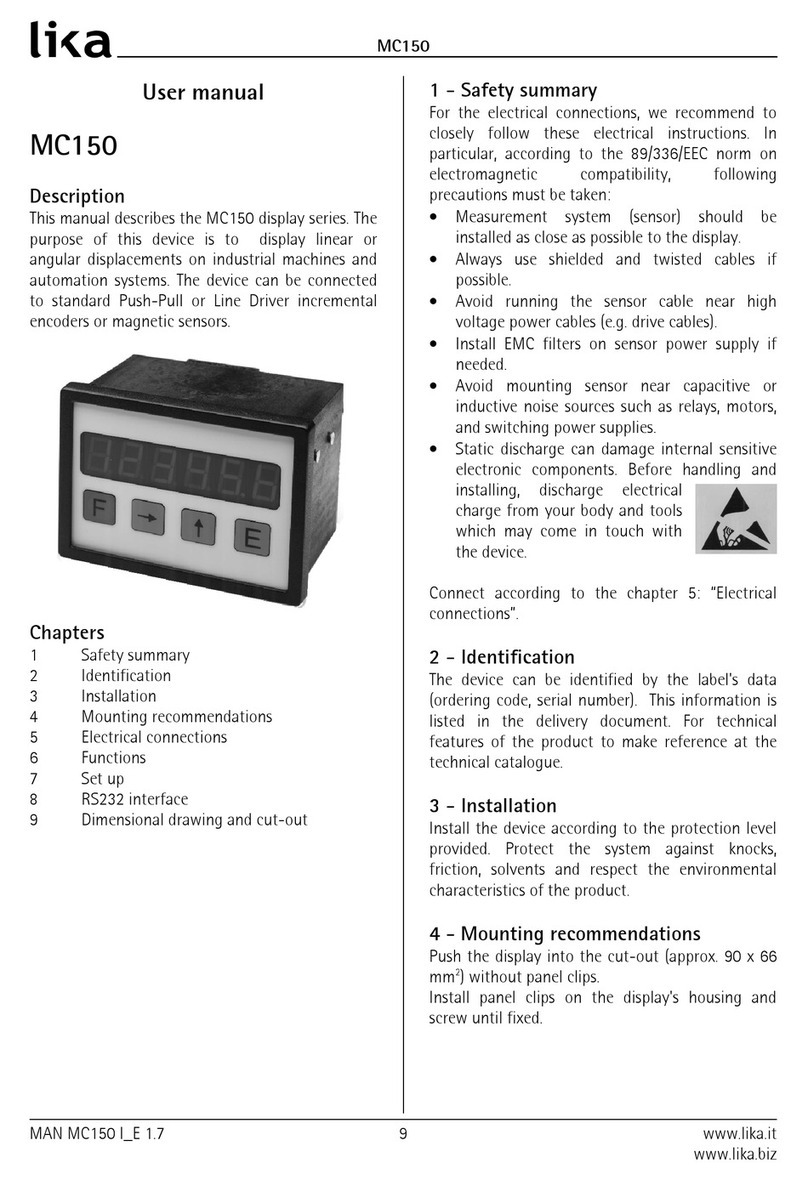
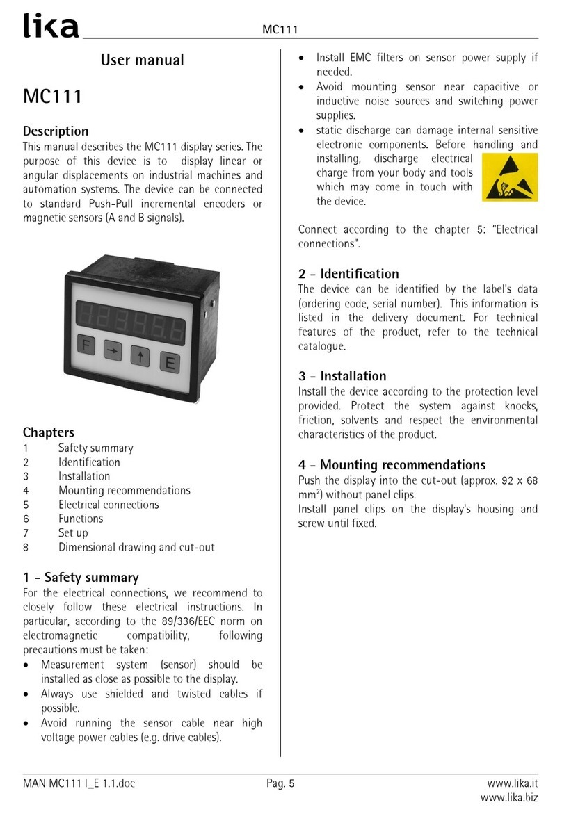
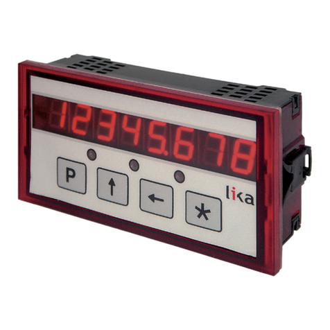
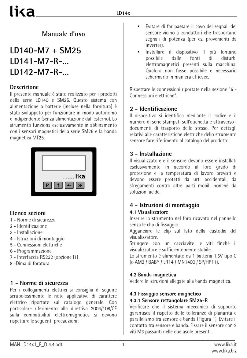
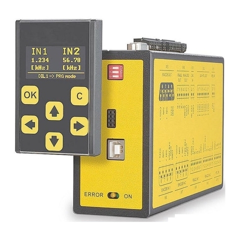
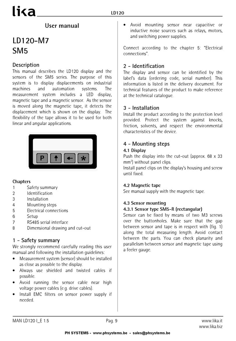
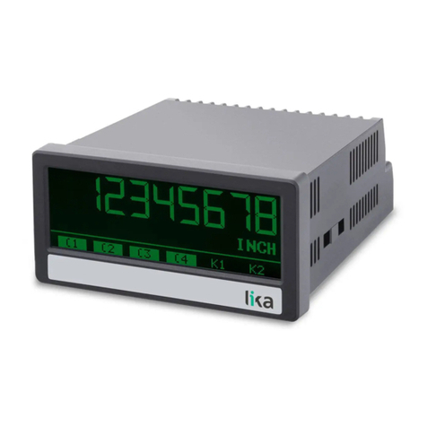
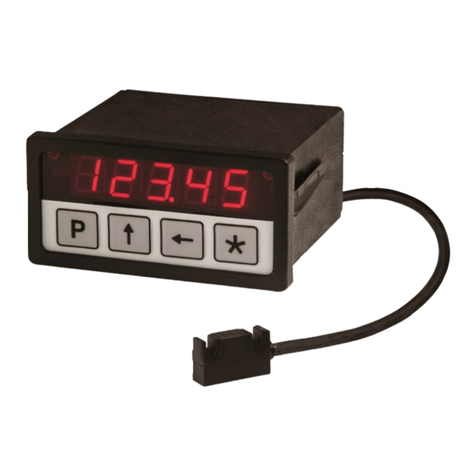
Lika LD14 Series User manual

LD14x
Manuale d’uso
LD140-M7 + SM25
LD141-M7R …
LD142-M7R …
Descrizione
Il presente manuale descrive i prodotti della serie
LD14x e SM25. Questo sistema con alimentazione a
batterie (incluse nella ornitura) è stato sviluppato
per unzionare in modo autonomo e indipendente
(senza alimentazione esterna). Lo strumento
unziona esclusivamente in abbinamento con i
sensori magnetici della serie SM25 e la banda
magnetica MT25.
Elenco sezioni
1 - Norme di sicurezza
2 - Identi icazione
3 - Installazione
4 - Istruzioni di montaggio
5 - Connessioni elettriche
6 - Programmazione
7 - Inter accia RS-232 (opzione I1)
8 -Dima di oratura
1 - Nor e di sicurezza
Per i collegamenti elettrici si consiglia di seguire
scrupolosamente le note applicative di carattere
elettrico riportate sul catalogo generale. Con
particolare ri erimento alla direttiva 2014/30/UE
sulla compatibilità elettromagnetica si devono
rispettare le seguenti precauzioni:
•Evitare di ar passare il cavo dei segnali del
sensore vicino a conduttori che trasportano
segnali di potenza (per es. provenienti da
inverter).
•Installare il dispositivo il più lontano possibile
dalle onti di disturbi elettromagnetici
presenti sulla macchina. Qualora non osse
possibile è necessario schermarlo in maniera
e icace.
Rispettare le connessioni riportate nella sezione “5 -
Connessioni elettriche”.
2 - Identificazione
Il dispositivo si identi ica mediante il codice e il
numero di serie stampati sull'etichetta e attraverso i
documenti di trasporto dello stesso. Per dettagli
relativi alle caratteristiche elettriche dello strumento
sensore are ri erimento al catalogo del prodotto.
3 - Installazione
Il visualizzatore e il sensore devono essere installati
esclusivamente in accordo al loro grado di
protezione e la temperatura di lavoro previsti e
devono essere protetti da urti accidentali, da
s regamenti contro altre parti mobili nonché da
soluzioni acide.
4 - Istruzioni di ontaggio
4.1 Visualizzatore
LD141: utilizzare quattro viti M2 x 14 con
distanziale.
LD140 / LD142: inserire lo strumento nel oro
ricavato nel pannello senza le clip di issaggio.
Agganciare le clip sul lato della custodia del
visualizzatore.
Stringere con un cacciavite le due viti M3 x 30
inché il visualizzatore è su icientemente stabile.
Lo strumento è alimentato da 1 batteria 1,5V tipo C
(o AM2 / BABY / LR14 / MN1400 / SP/HP11).
4.2 Banda agnetica
Vedere le istruzioni allegate alla banda magnetica.
4.3 Fissaggio sensore agnetico
4.3.1 Sensore rettangolare SM25-R
Veri icare che il sistema meccanico di supporto
garantisca il rispetto delle tolleranze di planarità e
parallelismo tra sensore e banda (Figura 1). Evitare il
____________________________________________________________________________________________
MAN LD14x I_E_D 4.5.odt 1 www.lika.it
www.lika.biz

LD14x
contatto tra sensore e banda. Fissare il sensore con 2
viti M3 passanti nelle due asole presenti.
Figura 1
Distanza sensore/ banda D = 0,1 - 1,0
4.3.2 Fissaggio sensore circolare SM25-C
Veri icare che il sistema meccanico di supporto
garantisca il rispetto delle tolleranze di planarità e
parallelismo tra sensore e banda ponendo particolare
attenzione all’allineamento tra il marker di
ri erimento e l’asse della banda magnetica (Figura 2).
Fissare il sensore (Ø 10 ) in un oro adeguato
mediante i due dadi orniti con il dispositivo.
Figura 2
Distanza sensore / anello D = 0,1 - 1,0
5 - Connessioni elettriche
5.1 Sensore SM25
(solo per LD140)
Connettere il sensore magnetico al connettore Mini-
DIN (circolare) presente sullo strumento.
5.2 Interfaccia seriale RS-232
(disponibile solo con opzione -I1)
Collegare il PC a LD14x mediante il cavo di tipo NULL
MODEM COMPUTER AT CROSS OVER (9 pin emmina
- 9 pin emmina) disponibile in commercio.
Connessioni elettriche:
Pin PC Funzione Pin LD14x
1 - -
2 Rx 3
3 Tx 2
4 DTR 6 *
5 GND 5
6 DSR -
7 RTS 8 *
8 CTS -
9 - -
* L’alimentazione ornita attraverso l’inter accia RS-
232 evita il consumo della batteria. Se LD14x non è
connesso al PC ornire l’alimentazione (8-15Vdc)
attraverso i pin 6 o 8. L’alimentazione esterna non è
necessaria se si usa un cavo Modem computer!
Impostare un indirizzo valido (da 1 a 31) per abilitare
la comunicazione seriale (de ault = 0).
6 - Progra azione
6.1 Funzione dei tasti
: UP (modi ica valore)
: Shi t le t (cambia ci ra)
* : Save (memorizza dato)
P : Program (scorre nel menu)
6.2 Co binazioni di tasti / Funzioni rapide
Di de ault le unzioni rapide sono tutte disabilitate.
6.2.1 Reset (o azzera ento)
Premendo il tasto * per ca. 3 sec. si accede alla
unzione di Reset (sul display compare “rESEt”).
Premere P per uscire (no reset).
Premere 2 volte * per con ermare il reset (sul display
____________________________________________________________________________________________
MAN LD14x I_E_D 4.5.odt 2 www.lika.it
www.lika.biz

LD14x
compare “donE”).
Il valore visualizzato è = rEF + OFS1 + OFSx (dove
OFSx è l'O set attualmente impostato).
La unzione è attiva solo se il parametro F_rSt è
impostato su “yES”.
6.2.2 Conteggio incre entale/assoluto
Premendo i tasti P e * il display commuta da
visualizzazione assoluta (punto decimale isso) a
incrementale (punto decimale lampeggiante) e
viceversa.
L’azzeramento -”6.2.1 Reset (o azzeramento)“- in
modalità incrementale non modi ica la quota
assoluta dello strumento.
La unzione è attiva solo se il parametro F_rEL è
impostato su “yES”.
6.2.3 Visualizzazione /pollici
Premendo il tasto per ca. 3 sec. il display
commuta l'unità di misura visualizzata da mm a
pollici (e viceversa). La unzione è attiva se il
parametro F_nnI è impostato su "yES".
6.2.4 Offset
Premendo i tasti P e si accede al primo valore di
O set (OFS1). Con i tasti e è possibile
modi icare il valore di OFS1 e memorizzarlo con il
tasto *. I valori OFS 2 e OFS 3 sono modi icabili
solo tramite set-up.
La unzione è attiva se il parametro F_oFS è
impostato su “yES”.
Premendo il tasto si visualizzano in sequenza i
valori OFS1, OFS 2 e OFS 3, dove:
OFS1 = quota attuale + OFS1 + rEF
OFS 2 = quota attuale + OFS1 + OFS 2 + rEF
OFS 3 = quota attuale + OFS1 + OFS 3 + rEF
6.2.4.1 Offset in pollici e frazioni
Con visualizzazione delle quote in pollici e razioni di
pollici la modi ica dei valori di O set (OFSx) avviene
come segue:
- 1° ci ra lampeggiante tasto increm. di 1/64".
- 2° ci ra lampeggiante tasto increm. di 1/32".
- 3° ci ra lampeggiante tasto increm. di 1/16".
- 4° ci ra lampeggiante tasto increm. di 1/8".
- 5° ci ra lampeggiante tasto incrementa di 1".
- 6° ci ra lampeggiante tasto increm. di 10".
6.2.5 Reference (o Preset)
Premendo i tasti P e si accede al valore di Preset
rEF. Con i tasti e è possibile modi icare il
valore di rEF e memorizzarlo con il tasto *.
La unzione è attiva se il parametro F_rEF è
impostato su “yES”
6.3 Setup
Premendo il tasto P per 3 sec. si entra in
programmazione. Sul display appare “SEtUP”.
Premendo il tasto si entra nel Menu 1, vedi
sezione “6.3.2 Elenco parametri MENU 1“.
Premendo il tasto * si entra nel Menu 2, vedi
sezione “6.3.4. Elenco parametri MENU 2“.
Con parametro visualizzato, premendo P si passa
dalla visualizzazione all'impostazione del parametro.
Premendo il tasto P per 3 sec. si esce dal set-up.
6.3.1 Para etri di default
I valori di de ault sono evidenziati in GRASSETTO.
Lo strumento può essere riportato alle impostazioni
di de ault (impostazione di abbrica) nel seguente
modo:
togliere la batteria e attendere 10 sec.;
inserire nuovamente la batteria tenendo
premuto il tasto * (si visualizza “dEFPar”).
6.3.2 Elenco para etri MENU 1
Unit
Unità di misura [dEc, FrEE, dG1, dG2, IdEc, IFrct]
Imposta unità di misura e modo di visualizzazione.
dEc = visualizzazione deci ale per misure lineari
FrEE = visualizz. con attore di conversione libero
dG1 = visualizz. angoli (-..-0,1°..0,0°..+0,1°..+)
dG2 = visualizz. angoli (..359,9°..0,0°..359,9°..0,0°..)
IdEc = pollici con decimali
IFrct = pollici con razioni (es. 12.31.64 = 12" 31/64)
* = salvare, P = prossimo, P x 3 sec. = uscire
COn
Fattore di conversione solo se Unit = FrEE, dG1, dG2
Permette di impostare un attore di conversione
della misura per visualizzare angoli o misure non
metriche.
Valori ammessi: 0,00001 – 9,99999 (1,00000)
0,00000 non applica attore di conversione.
____________________________________________________________________________________________
MAN LD14x I_E_D 4.5.odt 3 www.lika.it
www.lika.biz

LD14x
Ese pio 1
Si vuole visualizzare un angolo da 0° a 90° con
risoluzione 0,1° su una tavola girevole di diametro
250 mm.
La corsa su 360° pertanto è 250 * 3,14 = 785,4 mm;
su 90,0° è: 785,4 / 4 = 196,35 mm
COn = 900 : 19635 = 0,045836
Ese pio 2
Si vogliono visualizzare angoli con risoluzione 0,1° su
un anello magnetico di diametro 114,5 mm.
La circon erenza è 114,5 * 3,14 = 359,53 mm
COn = 3600 / 35953 = 0,10013
* = salvare, P = prossimo, P x 3 sec. = uscire
rES
(solo con Unit = dEc, FrEE, dG1, dG2, IdEc)
Impostazione della risoluzione da visualizzare.
Unit dEc, FrEE, dG1, dG2 = 0.001, 0.005, 0.01,
0.05, 0.1, 0.5, 1
Unit IdEc = 0.0001, 0.0005, 0.001, 0.005, 0.01,
0.05, 0.1
* = salvare, P = prossimo, P x 3 sec. = uscire
dir
Direzione di conteggio [uP, dn]
uP = direzione di conteggio standard
dn = direzione di conteggio invertita
* = salvare, P = prossimo, P x 3 sec. = uscire
6.3.3 Funzioni supple entari del MENU 1
F_nnI
Abilitazione mm/pollici [yES, no]
Abilitazione della unzione di passaggio da mm a
pollici e viceversa tramite tasto .
yES = abilitato
no = disabilitato
* = salvare, P = prossimo, P x 3 sec. = uscire
F_rEL
Abilitazione conteggio assoluto /increment. [yES, no]
Abilitazione della unzione di conteggio assoluto /
incrementale tramite combinazione di tasti P e *.
yES = abilitato
no = disabilitato
* = salvare, P = prossimo, P x 3 sec. = uscire
F_rSt
Abilitazione reset [yES, no]
Abilitazione della unzione di reset tramite tasto *.
yES = abilitato
no = disabilitato
Il display visualizza il valore rEF+OFS1+OFSx (dove
OFS x è l'O set attualmente impostato).
* = salvare, P = prossimo, P x 3 sec. = uscire
F_rEF
Abilitazione Preset [yES, no]
Abilitazione della modi ica del valore di Preset
tramite combinazione di tasti P e .
yES = abilitato
no = disabilitato
* = salvare, P = prossimo, P x 3 sec. = uscire
F_oFS
Abilitazione O set [yES, no]
Abilitazione della modi ica degli o set tramite
combinazione di tasti P e .
yES = abilitato
no = disabilitato
* = salvare, P = prossimo, P x 3 sec. = uscire
rEF
Valore di Preset [-999999, 999999, 000000]
Valore Preset (o Re erence). Può essere visualizzato
premendo il tasto * per 3 sec. (tiene conto anche dei
valori di O set impostati).
Parametro disponibile solo se F_rEF è abilitato.
* = salvare, P = prossimo, P x 3 sec. = uscire
OFS1
O set 1 [-999999, 999999, 000000]
Valore di o set (ad es. spessore utensile). Se
richiamato viene aggiunto alla quota attuale, vedi
sezione “6.2.4 O set“.
Parametro disponibile solo se F_oFS è abilitato.
* = salvare, P = prossimo, P x 3 sec. = uscire
OFS 2
O set 2 [-999999, 999999, 000000]
Secondo valore di o set (vedi anche parametro
precedente) aggiunto alla quota attuale e a OFS1.
Parametro disponibile solo se F_oFS è abilitato.
* = salvare, P = prossimo, P x 3 sec. = uscire
____________________________________________________________________________________________
MAN LD14x I_E_D 4.5.odt 4 www.lika.it
www.lika.biz
LD14x
OFS 3
O set 3 [-999999, 999999, 000000]
Terzo valore di o set (vedi anche parametro OFS1)
aggiunto alla quota attuale, a OFS1 e a OFS 2.
Parametro disponibile solo se F_oFS è abilitato.
* = salvare, P = prossimo, P x 3 sec. = uscire
Al termine del set-up compare la scritta “rESEt”.
Premendo 2 volte il tasto * si e ettua l'azzeramento
della quota e si esce dal set up (tiene conto di Preset
e O set). Appare “donE”.
Premendo il tasto P compare la scritta “no rSt”, non
si azzera la quota e si esce dal set-up.
6.3.4. Elenco para etri MENU 2
Ad xx
Indirizzo del dispositivo [00, 31, 00]
Impostazione dell'indirizzo del display per collegare
più dispositivi in rete seriale (opzione I1), indirizzi
validi da 01 a 31, 00 riservato per modalità
broadcast.
Usare i tasti e per impostare l’indirizzo.
* = salvare, P = prossimo
H cntr
Contaore (decimi di ora)
Visualizza in decimi di ora (6 min.) il tempo di
unzionamento dello strumento con alimentazione
collegata.
* = salvare, P = prossimo
7 - Interfaccia RS-232 (opzione I1)
Qualora lo strumento sia completo di porta seriale
RS-232 (opzione -I1) si possono eseguire i seguenti
comandi e impostazioni.
7.1 I postazioni porta seriale
Baud rate = 9600, Bit di dati = 8
Parità = nessuna, Bit di stop = 1
Controllo di lusso = Xon/Xo
7.2 Co andi porta seriale
La struttura dei comandi da inviare via seriale è la
seguente:
| A D C M N D = X C R L F
dove :
| è il carattere della tastiera PC (in alto a sinistra
sulla tastiera PC) = inizio comando
AD : indirizzo dispositivo (da 01 a 31), 2 caratteri
CMND : comando (vedi “7.2.1 Elenco comandi”)
X : eventuale valore da inviare (vedi sotto)
CR : Carriage Return = messaggio completato
LF : Line Feed = comando su riga successiva
Nel caso di invio errato il display risponde con lo
stesso comando inviato seguito da ? e checksum (es.:
comando inviato |02azs risposta 02azs?EF).
E' possibile inviare i comandi tramite qualsiasi
emulatore di terminale (ad es. Hyperterminal). Il
comando viene inviato alla pressione del tasto
ENTER (Carriage Return).
La struttura della risposta del display è la seguente:
ADCMND:SXXXXXXXXCHKSCR
dove:
AD : indirizzo dispositivo
CMND : comando
S : segno + / -
XXXXXXXX : valore
CHKS : Checksum
CR : Carriage Return = messaggio completato
Il checksum corrisponde al byte meno signi icativo
della somma di tutti i valori esadecimali dei caratteri
trasmessi.
Ese pio
La quota visualizzata corrisponde a 8,29. Si richiede
la quota al dispositivo con indirizzo 01 tramite il
comando |01TPOS:
|01TPOSCRLF = 7C 30 31 54 50 4F 53 0D 0A
La risposta sarà: 01TPOS:+000008299FCR = 30 31
54 50 4F 53 3A 2B 30 30 30 30 30 38 32 39 9F 0D
La somma dei valori esadecimali di ogni lettera
trasmessa è:
30+31+54+50+4F+53+3A+2B+30+30+30+30+30+
38+32+39 = 39F
Il byte meno signi icativo di 39F è pertanto 9F che
costituisce il checksum.
____________________________________________________________________________________________
MAN LD14x I_E_D 4.5.odt 5 www.lika.it
www.lika.biz

LD14x
7.2.1 Elenco co andi
(N.B.: di seguito con AD viene indicato in modo
generico l’indirizzo del dispositivo)
Azzera ento indirizzo display in rete
|00RSET
Impostazione a 0 dell’indirizzo di tutti i display
connessi in rete.
I postazione indirizzo display in rete [1, 31]
|00INIT=X
Assegnazione dell’indirizzo X a tutti i display in rete.
Visualizza indirizzo
|00DADR
Visualizzazione dell'indirizzo del display ino alla
pressione del tasto P.
I postazione indirizzo [1, 31]
|ADRADR=X
Impostazione dell’indirizzo da AD a X.
Risposta: ADTADR:+XCHKSCR (dove X è il valore,
CHKS è il checksum e CR il Carriage Return).
Lettura indirizzo
|ADTADR
Lettura dell'indirizzo impostato.
Risposta: ADTADR:+XCHKSCR
Lettura quota attuale
|ADTPOS
Lettura della quota attuale del display con indirizzo
AD (la quota viene inviata in centesimi di mm o
millesimi di pollice).
Risposta: ADTPOS:+XXXXXXXXCHKSCR
I postazione direzione conteggio [0, 1]
|ADRDIR=X
Impostazione della direzione di conteggio.
X=0 uP = direzione di conteggio standard
X=1 dn = direzione di conteggio invertita
Risposta: ADTDIR:+0000000XCHKSCR
Lettura direzione conteggio
|ADTDIR
Lettura della direzione di conteggio.
X=0uP , X=1dn
Risposta: ADTDIR:+0000000XCHKSCR
I postazione unità di isura [0, 5]
|ADRUNI=X
Impostazione dell’unità di misura del display.
X=0 dEc = visualizzazione decimale
X=1 FrEE = attore di conversione libero
X=2 dG1 = vis. angoli (-...-0,1°...0,0°...+0,1°...+)
X=3 dG2 = angoli (...359,9°...0,0°...359,9°...0,0°...)
X=4 IdEc = pollici con decimali
X=5 IFrct = poll. con raz. (es. 12.31.64 = 12" 31/64)
Risposta: ADTUNI:+0000000XCHKSCR
Lettura unità di isura
|ADTUNI
Lettura dell’unità di misura impostata.
Risposta: ADTUNI:+0000000XCHKSCR
I postazione risoluzione [1, 5, 10, 50, 100, 500, 1000]
|ADRRES=X
Valore della risoluzione lineare in mm o
pollici
.
X=1 0.001/
0.0001
, X=5 0.005/
0.0005
,
X=10 0.01/
0.001
, X=50 0.05/
0.005
,
X=100 0.1/
0.01
, X=500 0.5/
0.05
,
X=1000 1/
0.1
Risposta: ADTRES:+XCHKSCR
Lettura risoluzione
|ADTRES
Lettura della risoluzione lineare impostata.
Risposta: ADTRES:+XCHKSCR
I postazione fattore di conversione COn
[se FrEE 0,00001 - 1,00000 / se dG1, dG2 0,00001 - 9,99999]
|ADRCON=X
Impostazione del attore di conversione COn (vedi
parametri in “6.3.2 Elenco parametri MENU 1“).
Risposta: ADTCON:+XCHKSCR
Lettura fattore di conversione COn
|ADTCON
Lettura del attore di conversione COn impostato.
Risposta: ADTCON:+00X.XXXXCHKSCR
I postazione visualizzazione /pollici [0, 1]
|ADRMMI=X
Imposta la visualizzazione (non l'unità di misura) in
mm o pollici.
X=0 mm, X=1 pollici
Risposta: ADTMMI:+0000000XCHKSCR
____________________________________________________________________________________________
MAN LD14x I_E_D 4.5.odt 6 www.lika.it
www.lika.biz

LD14x
Lettura visualizzazione /pollici
|ADTMMI
Lettura dello stato della visualizzazione mm/pollici.
X=0 mm, X=1 pollici
Risposta: ADTMMI:+0000000XCHKSCR
Abilitazione conteggio assoluto/incre . [0, 1]
|ADRRAE=X
Abilitazione della unzione di conteggio assoluto /
incrementale (tramite combinazione di tasti P e *).
X=0 oFF, X=1 on
Risposta: ADTRAE:+0000000XCHKSCR
Lettura abilitazione conteggio assoluto/incre .
|ADTRAE
Lettura dello stato dell'abilitazione del conteggio
assoluto / incrementale.
X=0 oFF, X=1 on
Risposta: ADTRAE:+0000000XCHKSCR
I postazione conteggio assoluto/incre . [0, 1]
|ADRRLA=X
Impostazione del conteggio incrementale o assoluto.
X=0 assoluto, X=1 incrementale (relativo)
Risposta: ADTRLA:+0000000XCHKSCR
Lettura conteggio incre entale o assoluto
|ADTRLA
Lettura del tipo di visualizzazione (incrementale o
assoluta).
X=0 assoluta, X=1 incrementale (relativo)
Risposta: ADTRLA:+0000000XCHKSCR
Abilitazione funzione di Reset [0, 1]
|ADRRSE=X
Abilitazione della unzione di Reset tramite tasto *.
X=0 oFF, X=1 on
Risposta: ADTRSE:+0000000XCHKSCR
Lettura funzione di Reset
|ADTRSE
Lettura dello stato della unzione di Reset.
X=0 oFF, X=1 on
Risposta: ADTRSE:+0000000XCHKSCR
Abilitazione funzione di Reference [0, 1]
|ADRRFE=X
Abilitazione della unzione di Re erence (tramite
combinazione di tasti P e ).
X=0 oFF, X=1 on
Risposta: ADTRFE:+0000000XCHKSCR
Lettura funzione di Reference
|ADTRFE
Lettura dello stato della unzione di Re erence.
X=0 oFF, X=1 on
Risposta: ADTRFE:+0000000XCHKSCR
Abilitazione funzione di Offset [0, 1]
|ADROFE=X
Abilitazione della unzione di O set (tramite
combinazione P e ).
X=0 oFF, X=1 on
Risposta: ADTOFE:+0000000XCHKSCR
Lettura funzione di Offset
|ADTOFE
Lettura dello stato della unzione di O set.
X=0 oFF, X=1 on
Risposta: ADTOFE:+0000000XCHKSCR
I postazione valore di Reference [-999999, 999999]
|ADRREF=X
Impostazione del valore di Re erence (o Preset). Può
essere visualizzato premendo il tasto * per 3 sec.
(tiene conto anche dei valori di O set impostati e
deve essere espresso in centesimi).
Risposta: ADTREF:XCHKSCR
Lettura valore di Reference
|ADTREF
Lettura del valore di Re erence impostato.
Risposta: ADTREF:XCHKSCR
I postazione valore di Offset1 [-999999, 999999]
|ADROF1=X
Impostazione del valore di O set1 (impostare il
valore in centesimi).
Risposta: ADTOF1:XCHKSCR
Lettura valore di Offset1
|ADTOF1
Lettura del valore di O set1 impostato.
Risposta: ADTOF1:XCHKSCR
____________________________________________________________________________________________
MAN LD14x I_E_D 4.5.odt 7 www.lika.it
www.lika.biz

LD14x
I postazione valore di Offset2 [-999999, 999999]
|ADROF2=X
Impostazione del valore di O set2 (impostare valore
in centesimi).
Risposta: ADTOF2:XCHKSCR
Lettura valore di Offset2
|ADTOF2
Lettura del valore di O set2 impostato.
Risposta: ADTOF2:XCHKSCR
I postazione valore di Offset3 [-999999, 999999]
|ADROF3=X
Impostazione del valore di O set3 (impostare il
valore in centesimi).
Risposta: ADTOF3:XCHKSCR
Lettura valore di Offset3
|ADTOF3
Lettura del valore di O set3 impostato.
Risposta: ADTOF3:XCHKSCR
Tras issione para etri
|ADTALL
Comanda la trasmissione dei valori impostati nei
parametri descritti sopra. Il sistema restituisce in
sequenza la risposta riportata nella descrizione di
ciascun parametro. Per esempio:
ADTADR:+XCHKSCR
ADTUNI:+0000000XCHKSCR
...
8 -Di a di foratura
8.1 LD140 e LD142
Predisporre un oro rettangolare di 94 x 68 mm.
8.2 LD141
Si veda il disegno dettagliato sul catalogo del
prodotto.
Rev. Vers.Man. Descrizione
0 1.0 Prima stampa
4.1 Aggiornamento SW e manuale
3 4.2 Correzione sezione “5 - Connessioni
elettriche“
4 4.3 Correzione unzione Reset, sezione “6.2.1
Reset (o azzeramento)“
5 4.4 Revisione generale, aggiornamento “6.2.2
Conteggio incrementale/assoluto“
6 4.5 Revisione sezione “7.2 Comandi porta
seriale”, revisione generale
S altire separata ente
Lika Electronic
Via S. Lorenzo, 25 - 36010 Carrè (VI) - Italy
Tel. +39 0445 806600
Fax +39 0445 806699
Italy: eMail in [email protected] - www.lika.it
World: eMail in [email protected] - www.lika.biz
____________________________________________________________________________________________
MAN LD14x I_E_D 4.5.odt 8 www.lika.it
www.lika.biz

LD14x
User's anual
LD140-M7 + SM25
LD141-M7-R-…
LD142-M7-R-…
Description
This manual describes the LD14x battery display
series and the sensors o the SM25 series. This
system is designed to display linear or angular
displacements on industrial machines and
automation systems. The measurement system
includes a battery powered LCD display, a magnetic
scale and a magnetic sensor. As the sensor is moved
along the magnetic scale, it detects the displacement
which is shown on the display. The lexibility o the
scale allows or use in both linear and angular
applications.
Table of Contents
1 - Sa ety summary
2 - Identi ication
3 - Installation
4 - Mounting recommendations
5 - Electrical connections
6 – Set up
7 - RS-232 serial inter ace (option -I1)
8 - Cut-out
1 - Safety su ary
We strongly recommend the user manual and the
installation guidelines to be read and ollowed
care ully:
Sensor head should be installed as close as
possible to the display.
Avoid running the sensor cable near high voltage
power cables (e.g. drive cables).
Avoid mounting the sensor head near capacitive
or inductive noise sources such as relays, motors
and switching power supplies.
Connect according to “5 - Electrical connections“.
2 - Identification
Display and sensor data are shown in the label (order
code, serial number). The same in ormation is listed
in the delivery document too. For technical eatures
please re er to the product catalogue.
3 - Installation
Install the device according to the protection level
provided. Protect the system against knocks, riction,
solvents, temperatures below –0°C (32°F) and over
+60°C (+140°F).
Be sure that the system is mounted where hard or
sharp objects (e.g. metal chips) do not come into
contact with the magnetic scale and the bottom o
the sensor head. I these conditions cannot be
avoided provide a wiper or pressurized air.
4 - Mounting reco endations
4.1 Mounting the display
LD141: use four M2 x 14 screws with spacer.
LD140 / LD142: mount the display through the
enclosure cut-out without mounting clips.
Install the clips in the display enclosure and screw
them until the display is ixed and stable (use two
M3 x 30 screws).
Power supply rom 1.5V commercial battery type C
(or AM2 / BABY / LR14 / MN1400 / SP/HP11).
4.2 Mounting the agnetic scale
Re er to the manual supplied with the scale.
4.3 Mounting the sensor
4.3.1 Sensor SM25-R (rectangular)
The sensor can be ixed by means o two M3 screws
inserted in the buttonholes. Make sure that the gap
between the sensor and the scale complies with the
values in Figure 1 along the whole measuring length.
Avoid contact between the parts. You can check
planarity and parallelism between the sensor and the
magnetic scale using a eeler gauge.
____________________________________________________________________________________________
MAN LD14x I_E_D 4.5.odt 9 www.lika.it
www.lika.biz

LD14x
Figure 1
Distance sensor / tape D = 0.1 – 1.0
4.3.2 Sensor SM25-C (circular)
The sensor can be ixed in a corresponding mounting
hole by means o the two nuts. Make sure that the
gap between the sensor and the scale complies with
the values in Figure 2 along the whole measuring
length. Please ind the correct align ent of the
arker on the tape. Avoid contact between the
parts. You can check planarity and parallelism
between the sensor and the magnetic scale using a
eeler gauge.
Figure 2
Distance sensor / ring D = 0.1 – 1.0
5 - Electrical connections
5.1 SM25 sensor
(LD140 only)
Plug in the sensor's Mini-DIN connector (circular) on
the backside o the display.
5.2 RS-232 serial interface
(option -I1 only)
Connect the PC to the LD14x panel with a NULL
MODEM COMPUTER AT CROSS OVER cable (9 pin
emale - 9 pin emale) commercially available.
Electrical cable connection:
Pin PC Function Pin LD14x
1 - -
2 Rx 3
3 Tx 2
4 DTR 6 *
5 GND 5
6 DSR -
7 RTS 8 *
8 CTS -
9 - -
* Power supply has to be provided to RS-232
inter ace to save battery li e. I not connected to the
PC provide (8-15Vdc) power supply to pins 6 or 8.
The external supply is not necessary i you use a
Modem computer cable!
Set a valid address ( rom 1 to 31) to enable the serial
communication (de ault = 0).
6 – Set up
6.1 Function of the keys
: UP (select value)
: Shi t le t (select digit)
* : Save (save data)
P : Program (programming/change parameter)
6.2 Key co binations / Quick functions
By de ault the quick unctions are disabled.
6.2.1 Reset (zero-setting)
Press * key or 3 sec. to access the reset unction
(“rESEt” will be displayed).
____________________________________________________________________________________________
MAN LD14x I_E_D 4.5.odt 10 www.lika.it
www.lika.biz

LD14x
Press P key to exit the unction (no reset).
Press * key twice to con irm the reset operation
(“donE” will be displayed).
Displayed value = rEF + OFS1 + OFSx (where OFSx
is the O set value currently set).
This unction is enabled only i F_rSt parameter is
set to “yES”.
6.2.2 Incre ental/absolute easure ent
Press P and * keys simultaneously to switch rom
absolute (decimal point lit solidly) to incremental
(blinking decimal point) measurement and vice versa.
Zero setting in incremental mode (see “6.2.1 Reset
(zero-setting)“) does not change the absolute value
in the background.
The unction is enabled only i F_rEL parameter is
set to "yES".
6.2.3 M /inch display ode
Mm/inch display mode can be switched by pressing
key or 3 sec. The unction is enabled only i
F_nnI parameter is set to "yES".
6.2.4 Changing the Offset value
Press P and keys simultaneously to display the
O set value 1 (OFS1). Use and keys to change
the value and save pressing * key. OFS 2 and OFS
3 O set values can be changed only in set up menu.
O set unction is enabled i F_oFS parameter is set
to “yES”.
key scrolls through OFS1, OFS 2 and OFS 3
values.
OFS1 = current value + OFS1 + rEF
OFS 2 = current value + OFS1 + OFS 2 + rEF
OFS 3 = current value + OFS1 + OFS 3 + rEF
6.2.4.1 Fractional inch offset display
The ractional inch display mode allows to set o set
values (OFSx) in the ollowing way:
- 1st digit blinking increases 1/64” pressing key.
- 2nd digit blinking increases 1/32” pressing key.
- 3rd digit blinking increases 1/16” pressing key.
- 4th digit blinking increases 1/8” pressing key.
- 5th digit blinking increases 1” pressing key.
- 6th digit blinking increases 10” pressing key.
6.2.5 Reference (o Preset) setting
Press P and keys simultaneously to display the
Preset value rEF. Use and keys to change the
value and save pressing * key.
This unction is enabled only i F_rEF parameter is
set to “yES”.
6.3 Setup / Para eter setting
Press P key or 3 sec. to enter set up mode, “SEtUP”
is displayed.
Press key to enter MENU 1 (parameters), see
“6.3.2 MENU 1 Parameter list” section.
Press * key to enter MENU 2 (RS-232 serial
inter ace), see “6.3.4 MENU 2 Parameter list” section.
With displayed parameter, press P key to switch rom
display to setting mode.
Press P key or 3 sec. to exit the set up at any point.
6.3.1 Default para eters (factory settings)
De ault values are highlighted in BOLD characters.
The display can be reset to de ault ( actory)
parameters by executing the ollowing procedure:
•remove the battery and wait 10 sec.;
•press * key while inserting the battery
(“dEFPar” is displayed).
6.3.2 MENU 1 Para eter list
Unit
Measurement unit [dEc, FrEE, dG1, dG2, IdEc, IFrct]
It sets the measurement unit and the display mode.
dEc = linear easure ent display (deci al)
FrEE = display with ree conversion actor
dG1 = angular display (-...-0.1°...0.0°...+0.1°...+)
dG2 = angular display (...359.9°...0.0°...359.9°...0.0°...)
IdEc = decimal inch display mode
Ifrct = ractional inch mode (eg. 12.31.64= 12" 31/64)
* = save, P = next parameter, P or 3 sec. = exit
COn
Conversion actor only i Unit = FrEE, dG1, dG2
It allows to set a ree conversion actor to display
non-metric units or angles.
Value range: 0.00001 – 9.99999 (1.00000)
0.00000 does not apply any conversion actor.
Exa ple 1
We want to display a 90° angle ( rom 0° to 90°) with
0.1° resolution on a 250 mm diameter rotary table.
The measurement length is 250 * 3.14 = 785.4 mm
____________________________________________________________________________________________
MAN LD14x I_E_D 4.5.odt 11 www.lika.it
www.lika.biz

LD14x
on 360°, thus it is 785.4 / 4 = 196.35 on 90.0°.
COn = 900 / 19635 = 0.045836
Exa ple 2
We want to display angles with 0.1° resolution on a
114.5 mm diameter magnetic ring.
The circum erence is 114.5 * 3.14 = 359.53 mm
COn = 3600 / 35953 = 0.10013
* = save, P = next parameter, P or 3 sec. = exit
rES
(only with Unit = dEC, FrEE, dG1, dG2, IdEc)
It sets the resolution to be displayed.
Unit = dEC, FrEE, dG1, dG2 = 0.001, 0.005, 0.01,
0.05, 0.1, 0.5, 1
Unit = IdEc = 0.0001, 0.0005, 0.001, 0.005, 0.01,
0.05, 0.1
* = save, P = next parameter, P or 3 sec. = exit
dir
Counting direction [uP, dn]
uP = up (standard counting direction)
dn = down (reversed counting direction)
* = save, P = next parameter, P or 3 sec. = exit
6.3.3 MENU 1 additional functions
F_nnI
mm/inch unction enable [yES, no]
It enables the mm/inch unction (pressing key).
yES = enabled
no = disabled
* = save, P = next parameter, P or 3 sec. = exit
F_rEL
Absolute/Increm. measurement unction [yES, no]
It enables the absolute/incremental measurement
unction (by pressing P and * keys).
yES = enabled
no = disabled
* = save, P = next parameter, P or 3 sec. = exit
F_rSt
Reset unction enable [yES, no]
It enables the reset unction (pressing * key).
yES = enabled
no = disabled
The display shows rEF + OFS1 + OFSx (where OFS
x is the O set value currently set).
* = save, P = next parameter, P or 3 sec. = exit
F_rEF
Preset setting unction enable [yES, no]
It enables the re erence (Preset) modi ication
unction (pressing P and keys).
yES = enabled
no = disabled
* = save, P = next parameter, P or 3 sec. = exit
F_oFS
O set setting unction enable [yES, no]
It enables the o set modi ication unction (pressing
P and keys).
yES = enabled
no = disabled
* = save, P = next parameter, P or 3 sec. = exit
rEF
Preset value [-999999, 999999, 000000]
Absolute re erence (Preset) value or the measuring
system. This value is displayed by pressing * key or
3 sec. (displayed value includes the o set values
previously set).
Only available i F_rEF is enabled.
* = save, P = next parameter, P or 3 sec. = exit
OFS1
O set1 value [-999999, 999999, 000000]
First o set value (e.g. tool thickness). This value is
added to the current position value (see “6.2.4
Changing the O set value“ section).
Only available i F_oFS is enabled.
* = save, P = next parameter, P or 3 sec. = exit
OFS 2
O set2 value [-999999, 999999, 000000]
Second O set value (see OFS1 above). This value is
added to the current value and OFS1 value.
Only available i F_oFS is enabled.
* = save, P = next parameter, P or 3 sec. = exit
____________________________________________________________________________________________
MAN LD14x I_E_D 4.5.odt 12 www.lika.it
www.lika.biz

LD14x
OFS 3
O set3 value [-999999, 999999, 000000]
Third O set value (see OFS1 above). This value is
added to the current value, to OFS1 and to OFS 2.
Only available i F_oFS is enabled.
* = save, P = next parameter, P or 3 sec. = exit
When the set up is carried out the display shows
"rESEt".
Press * key twice to reset the display and quit the
set up (Preset and O set values are calculated).
"donE" will be displayed.
Press P key to quit the set up without resetting the
display. "no rSt" will be displayed.
6.3.4 MENU 2 Para eter list
Ad xx
Device address [00, 31, 00]
It sets the device address or network connection,
only i the device is itted with serial inter ace
(option I1), valid values are rom 01 to 31, 00 is
reserved to broadcast mode.
Use and keys to set the address.
* = save, P = next parameter
H cntr
Hour meter (1/10 h)
Elapsed time indication (display connected to
battery). Resolution is 1/10 o an hour (6 minutes).
* = save, P = next parameter
7 - RS-232 serial interface (option -I1)
I the display is equipped with RS-232 serial
inter ace (option -I1), the commands described
herea ter can be used to communicate.
7.1 RS-232 para eters
9600 Baud rate, 8Bit, no Parity, 1 Stop bit, Xon/Xo
7.2 Serial co ands
Serial commands must have the ollowing structure:
| A D C M N D = X C R L F
where:
|: PC keyboard symbol = beginning o the command
AD: device address (01 to 31), 2 digits
CMND: command (see “7.2.1 Command list”)
X: value to be sent i requested (see below)
CR: Carriage Return = message completed
LF: Line Feed = new command in the ollowing line
Upon receipt o a wrong command the display will
respond with the same command + ? and checksum
(e.g. sent command: |02azs Response 02azs?EF).
Any common terminal program can be used or
communication with LD14x (e.g. Hyperterminal).
Commands will be sent a ter con irmation by ENTER
key (Carriage Return).
Responses have the ollowing structure:
ADCMND:SXXXXXXXXCHKSCR
where:
AD: device address
CMND: command
S: + / - sign
XXXXXXXX: value
CHKS: checksum
CR: Carriage Return = message completed
The checksum corresponds to the least signi icant
byte resulting rom the sum o the hex values o all
transmitted characters.
Exa ple
The displayed position is 8.29. The position o the
device with address 01 is read by means o the
|01TPOS command:
|01TPOSCRLF = 7C 30 31 54 50 4F 53 0D 0A
The response is: 01TPOS:+000008299FCR = 30 31 54
50 4F 53 3A 2B 30 30 30 30 30 38 32 39 9F 0D
The sum o hex values o all characters is as ollows:
30+31+54+50+4F+53+3A+2B+30+30+30+30+30+
38+32+39 = 39F
The least signi icant byte o 39F is 9F which is the
checksum.
____________________________________________________________________________________________
MAN LD14x I_E_D 4.5.odt 13 www.lika.it
www.lika.biz

LD14x
7.2.1 Co and list
(Device address is indicated with AD in the text)
All devices address zero-setting
|00RSET
The address o all connected devices is set to zero (0).
All devices address setting [1, 31]
|00INIT=X
It sets to X the address o all connected devices.
Device address reading
|00DADR
It displays the device address until P key is pressed.
Device address setting [1, 31]
|ADRADR=X
It changes the current device address AD to X.
Response: ADTADR:+XCHKSCR (CHKS is the
checksum, X is the value, CR is the Carriage Return).
Current position reading
|ADTPOS
It shows the current position o the device having
address AD (resolution is 0.01 mm or 0.001 inch
depending on settings).
Counting direction setting [0, 1]
|ADRDIR=X
It sets the counting direction.
X=0 uP = standard direction
X=1 dn = reversed direction
Response: ADTDIR:+0000000XCHKSCR
Counting direction reading
|ADTDIR
It shows the current counting direction.
X=0uP , X=1dn
Response: ADTDIR:+0000000XCHKSCR
Measure ent unit setting [0, 5]
|ADRUNI=X
It sets the measurement unit and the display mode.
X=0 dEc = decimal mode
X=1 FrEE = display with ree conversion actor
X=2 dG1 = angular (-..-0,1°..0.0°..+0.1°..+)
X=3 dG2 = angular (..359.9°..0.0°..359.9°..0.0°..)
X=4 IdEc = decimal inch display mode
X=5 IFrct = ractional inch (es. 12.31.64= 12" 31/64)
Response: ADTUNI:+0000000XCHKSCR
Measure ent unit reading
|ADTUNI
It shows the measurement unit currently set.
Response: ADTUNI:+0000000XCHKSCR
Resolution setting [1, 5, 10, 50, 100, 500, 1000]
|ADRRES=X
It sets the linear resolution in mm or
inch
.
X=1 0.001/
0.0001
, X=5 0.005/
0.0005
,
X=10 0.01/
0.001
, X=50 0.05/
0.005
,
X=100 0.1/
0.01
, X=500 0.5/
0.05
,
X=1000 1/
0.1
Response: ADTRES:+XCHKSCR
Resolution reading
|ADTRES
It shows the current resolution value (see values
above).
Response: ADTRES:+XCHKSCR
COn conversion factor setting
[with FrEE 0.00001 – 1.00000 / with dG1, dG2 0.00001 – 9.99999]
|ADRCON=X
It sets the COn conversion actor (see 6.3.2 MENU 1
Parameter list).
Response: ADTCON:+XCHKSCR
COn conversion factor reading
|ADTCON
It shows the value o the current COn actor.
Response: ADTCON:+00X.XXXXCHKSCR
M /inch display ode setting [0, 1]
|ADRMMI=X
It set the display mode between mm and inch.
X=0 mm, X=1inch
Response: ADTMMI:+0000000XCHKSCR
M /inch display ode reading
|ADTMMI
It shows the mm/inch display mode currently set.
X=0 mm, X=1 inch
Response: ADTMMI:+0000000XCHKSCR
Absolute/Incre ental easure ent enable [0, 1]
____________________________________________________________________________________________
MAN LD14x I_E_D 4.5.odt 14 www.lika.it
www.lika.biz

LD14x
|ADRRAE=X
It enables the absolute/incremental measurement
unction (key combination P and *).
X=0 oFF , X=1 on
Response: ADTRAE:+0000000XCHKSCR
Abs./Incre . easure ent enable reading
|ADTRAE
It shows whether the absolute/incremental
measurement unction is enabled.
X=0 oFF, X=1 on
Response: ADTRAE:+0000000XCHKSCR
Absolute/Incre ental easure ent setting [0, 1]
|ADRRLA=X
It switches rom absolute display mode to
incremental display mode (relative).
X=0 absolute, X=1 incremental (relative)
Response: ADTRLA:+0000000XCHKSCR
Abs./Incre . easure ent reading
|ADTRLA
It shows the absolute/incremental display mode
currently set.
X=0 absolute, X=1 incremental (relative)
Response: ADTRLA:+0000000XCHKSCR
Reset function enable setting [0, 1]
|ADRRSE=X
It enables the Reset unction (pressing * key).
X=0 oFF, X=1 on
Response: ADTRSE:+0000000XCHKSCR
Reset function enable reading
|ADTRSE
It shows whether the Reset unction is enabled.
X=0 oFF, X=1 on
Response: ADTRSE:+0000000XCHKSCR
Reference function enable setting [0, 1]
|ADRRFE=X
It enables the Preset unction (by P and key
combination).
X=0 oFF, X=1 on
Response: ADTRFE:+0000000XCHKSCR
Reference function enable reading
|ADTRFE
It shows whether the Preset unction is enabled.
X=0 oFF, X=1 on
Response: ADTRFE:+0000000XCHKSCR
Offset function enable setting [0, 1]
|ADROFE=X
It enables the O set unction (by P and key
combination.
X=0 oFF, X=1 on
Response: ADTOFE:+0000000XCHKSCR
Offset function enable reading
|ADTOFE
It shows whether the O set unction is enabled.
X=0 oFF, X=1 on
Response: ADTOFE:+0000000XCHKSCR
Reference value setting [-999999, 999999]
|ADRREF=X
It sets the Re erence (or Preset) value or the
measurement system (the value has resolution 0.01
mm or 0.001 inch depending on the display settings).
Response: ADTREF:XCHKSCR
Reference value reading
|ADTREF
It shows the Re erence value currently set.
Response: ADTREF:XCHKSCR
Offset1 value setting [-999999, 999999]
|ADROF1=X
It sets the O set1 value (the value has resolution
0.01).
Response: ADTOF1:XCHKSCR
Offset1 value reading
|ADTOF1
It shows the O set1 value currently set.
Response: ADTOF1:XCHKSCR
Offset2 value setting [-999999, 999999]
|ADROF2=X
It sets the O set2 value (the value has resolution
0.01).
Response: ADTOF2:XCHKSCR
____________________________________________________________________________________________
MAN LD14x I_E_D 4.5.odt 15 www.lika.it
www.lika.biz

LD14x
Offset2 value reading
|ADTOF2
It shows the O set2 value currently set.
Response: ADTOF2:XCHKSCR
Offset3 value setting [-999999, 999999]
|ADROF3=X
It sets the O set3 value (the value has resolution
0.01).
Response: ADTOF3:XCHKSCR
Offset3 value reading
|ADTOF3
It shows the O set3 value currently set.
Response: ADTOF3:XCHKSCR
Trans it all para eters
|ADTALL
It commands the transmission o all the above
described parameters. The display sends back the
responses reported under each item in sequence. For
instance:
ADTADR:+XCHKSCR
ADTUNI:+0000000XCHKSCR
...
8 - Cut-out
8.1 LD140 and LD142
Provide a 94 x 68 mm (w x h) cut-out.
8.2 LD141
Check details on product catalogue.
Rel. Man.Vers. Description
0 1.0 1^ issue
4.1 SW + Manual update
3 4.2 Section “5 - Electrical connections” update
4 4.3 Reset unction section “6.2.1 Reset (zero-
setting)“ update
5 4.4
General review, section “6.2.2
Incremental/absolute measurement”
update
6 4.5 Section “7.2 Serial commands” updated,
general review
Dispose separately
LIKA Electronic
Via S. Lorenzo, 25 - 36010 Carrè (VI) - Italy
Tel. +39 0445 806600
Fax +39 0445 806699
Italy: eMail in [email protected] - www.lika.it
World: eMail in [email protected] - www.lika.biz
____________________________________________________________________________________________
MAN LD14x I_E_D 4.5.odt 16 www.lika.it
www.lika.biz

LD14x
Betriebsanleitung
LD140-M7 + SM25
LD141-M7-R-…
LD142-M7-R-…
Beschreibung
Diese Betriebsanleitung enthält In ormationen und
Anwendungshinweise ür die Produkte der Serie
LD14x, SM25 und MT25.
Dieses Messsystem ist ür allgemeine Weg- und
Winkelmessungen in industriellen Bereichen
geeignet und besteht aus einer batteriebetriebenen
Anzeige, einem Sensor und einem Magnetband.
Der Sensor er asst die Position während er über das
Magnetband bewegt wird. Die Position wird au der
Anzeige dargestellt.
Inhalt
1 - Sicherheitshinweise
2 - Identi ikation
3 - Inbetriebnahme
4 - Montagehinweise
5 - Elektrischer Anschluss
6 - Parameter und Funktionsebene
7 - RS-232 Schnittstelle (Option -I1)
8 - Ausbruchsmaße
1 - Sicherheitshinweise
Bitte lesen Sie dieses Dokument vor der
Inbetriebnahme und Montage sorg ältig durch. Des
weiteren sollten beim elektrischen Anschluss
olgende Hinweise, gemäß der EMC-Vorschri ten,
beachtet werden.
Signalkabel sollten in möglichst großem Abstand
zu Leitungen, die mit Störungen belastet sind
verlegt werden (z.B. Antriebskabel, Inverterkabel,
usw.).
Das Gerät muss in möglichst großem Abstand zu
Antrieben, Invertern, usw. installiert werden oder
gg . durch Schirmbleche davon geschützt werden.
Stecker- oder Kabelbelegung sind am Produkt selbst
und in diesem Dokument beschrieben.
2 - Identifikation
Die Produkte können durch den Bestellschlüssel und
die Seriennummer au dem Typenschild identi iziert
werden. Diese In ormationen sind auch in den
Lie erdokumenten enthalten.
3 - Inbetriebnah e
Das gesamte System dar nur gemäß dem
angegebenen Schutzgrad und Arbeitstemperatur
eingesetzt werden. Sensor und Magnetband sollten
zusätzlich gegen Schläge, Reibung und
Lösungsmittel geschützt werden.
4 - Montagehinweise
4.1 Anzeige
LD141: das Gerät mit vier M2 x 14 Schrauben und
Abstandsstück be estigen.
LD140 / LD142: das Gerät wird in eine Schaltta el
mit einem geeigneten Ausbruch einge ührt und über
die Halter estgeschraubt.
Die Versorgung des Geräts er olgt mittels einer 1,5V
Batterie Type C (oder AM2 / BABY / LR14 / MN1400 /
SP/HP11).
4.2 Magnetband
Siehe Betriebsanleitung "Magnetband".
4.3 Montage Magnetsensor
4.3.1 Rechteckiger Sensor SM25-R
Die Mechanik bzw. Montagewinkel müssen au
dem gesamten Messweg die vorgegebenen
Toleranzen zwischen Sensor und Band
gewährleisten (s. Abbildung 1).
Der Kontakt zwischen Sensor und Band muss
verhindert werden.
Magnetsensor mit zwei M3 Schrauben an den
Langlöchern be estigen und gg . justieren.
____________________________________________________________________________________________
MAN LD14x I_E_D 4.5.odt 17 www.lika.it
www.lika.biz

LD14x
Abbildung 1
D = 0,1 - 1,0 mm
4.3.2 Runder Sensor SM25-C
Die Mechanik bzw. Montagewinkel müssen au
dem gesamten Messweg die vorgegebenen
Toleranzen zwischen Sensor und Band
gewährleisten (s. Abbildung 2).
Ein Kontakt zwischen Sensor und Band muss
verhindert werden.
Magnetsensor mit den zwei Muttern anziehen,
dabei besonders au die Zählrichtungsmarkierung
achten.
Abbildung 2
D = 0,1 – 1,0 mm
5 - Elektrischer Anschluss
5.1 Sensor SM25
(nur LD140)
Der Sensor kann direkt über den MiniDIN-Stecker an
die Anzeige angeschlossen werden.
5.2 Serielle Schnittstelle RS-232
(nur mit Option -I1 ver ügbar)
Die anzeige kann mit einem handelsüblichen NULL
MODEM COMPUTER AT CROSS OVER Kabel direkt an
einen PC angeschlossen werden. Kabelbelegung der
DSub-Stecker zwischen LD14x und PC ist wie olgt:
Pin PC Funktion Pin LD14x
1 - -
2 Rx 3
3 Tx 2
4 DTR 6 *
5 GND 5
6 DSR -
7 RTS 8 *
8 CTS -
9 - -
* Um die Betriebszeit der Batterie zu verlängern,
muss sie über die RS-232 Schnittstelle mit Spannung
versorgt werden. Falls nicht mit dem PC verbunden,
geben Sie eine Spannung (8-15Vdc) au Pin 6 oder 8.
Die externe Versorgung kann ent allen, wenn Sie ein
Modemkabel verwenden.
Um die serielle Kommunikation zu aktivieren
(Standard = 0), eine gültige Adresse einstellen (von 1
bis 31).
6 - Para eter und Funktionsebene
6.1 Funktion der Tasten
: UP (Wert inkrementieren)
: Shi t links (Dekadenwechsel)
* : Save (Daten speichern)
P : Program (Programmiertaste/Parameterwechsel)
6.2 Tastenko binationen
Standardmäßig sind die Tastenkombinationen
deaktiviert.
____________________________________________________________________________________________
MAN LD14x I_E_D 4.5.odt 18 www.lika.it
www.lika.biz

LD14x
6.2.1 Referenzwert (oder Eichung)
Nach Betätigung der Taste * ür ca. 3 s gelangt man
in Eichebene („rESEt" wird angezeigt).
Mit der Taste P verlässt man die Ebene (kein Reset).
Nach 2-maligem betätigen der Taste * wird die
Anzeige geeicht („donE " wird angezeigt).
Dieser ergibt sich aus rEF + OFS1 + OFSx (wobei
OFSx der jeweils eingestellte O set Wert ist).
Die Funktion ist nur dann aktiv wenn Parameter
F_rSt au „yES” eingestellt ist.
6.2.2 Ketten aß
Nach Betätigung der Tasten P und * wird die
Anzeige von Absolute- au Relativmaß (blinkender
Dezimalpunkt) umgestellt.
Die Nullstellung (siehe „6.2.1 Re erenzwert (oder
Eichung)„) im Relativmaßmodus ändert den
absoluten Wert im Hintergrund nicht.
Die Funktion ist nur dann aktiv wenn Parameter
F_rEL au „yES” eingestellt ist.
6.2.3 Anzeige odus /inch
Nach Betätigung der Taste ür ca. 3 s. wird der
Anzeigemodus von mm au Inch (Zoll) gewechselt.
Die Funktion ist nur dann aktiv wenn Parameter
F_nnI au „yES” eingestellt ist.
6.2.4 Offset (oder Versatz aß)
Mit der Tastenkombination P und wird der 1.
O setwert (OFS1) angezeigt. Mit den Tasten und
ist es möglich den Wert zu ändern und mit * zu
speichern. Die weiteren O setwerte OFS 2 und
OFS 3 können nur in der Parameterebene geändert
werden.
Die Funktion ist nur dann aktiv wenn Parameter
F_oFS au „yES” eingestellt ist.
Mit der Taste ist es möglich OFS1, OFS 2 und
OFS 3 nacheinander abzuru en.
OFS1 = Istwert + OFS1 + rEF
OFS 2 = Istwert + OFS1 + OFS 2 + rEF
OFS 3 = Istwert + OFS1 + OFS 3 + rEF
6.2.4.1 Offset it Inch Bruchteilung
Beim Anzeigemodus Inch mit Bruchteilung er olgt
die Änderung der O setwerte (OFSx) wie olgt:
- 1. Dekade blinkt Taste erhöht um 1/64".
- 2. Dekade blinkt Taste erhöht um 1/32".
- 3. Dekade blinkt Taste erhöht um 1/16".
- 4. Dekade blinkt Taste erhöht um 1/8".
- 5. Dekade blinkt Taste erhöht um 1".
- 6. Dekade blinkt Taste erhöht um 10".
6.2.5 Referenzwert (oder Preset)
Mit der Tastenkombination P e wird der
Re erenzwert rEF angezeigt. Mit den Tasten und
ist es möglich den Wert zu ändern und mit * zu
speichern.
Die Funktion ist nur dann aktiv wenn Parameter
F_rEF au „yES” eingestellt ist.
6.3 Para etereingabe (Setup)
Nach Betätigung der Taste P ür ca. 3 s wechselt man
von Anzeigemodus zu Parameterebene. Es wird
„SEtUP” angezeigt.
Mit Taste wechselt man zu MENÜ 1 (Parameter),
siehe „6.3.2 Parameterliste MENÜ 1“.
Mit Taste * wechselt man zu MENÜ 2 (RS-232),
siehe „6.3.4 Parameterliste MENÜ 2“.
Wenn der Parameter angezeigt wird, mit Taste P
wechselt man vom Parameter zur Parametereingabe.
Mit Taste P ür ca. 3 s verlässt man die
Parameterebene.
6.3.1 Werkseinstellungen (Default Para eter)
Werkseinstellungen sind FETT gedruckt.
Die Anzeige kann wie olgt au Werkseinstellung
zurückgesetzt werden:
Batterie ent ernen und ca. 10 s. Warten;
Batterie wieder ein ügen und gleichzeitig Taste *
betätigen („dEFPar“ wird angezeigt).
6.3.2 Para eterliste MENÜ 1
Unit
Messeinheit [dEc, FrEE, dG1, dG2, IdEc, IFrct]
Messeinheit und Anzeigemodus werden gesetzt.
dEc = Metrische Messeinheit (Linearmessungen)
FrEE = rei einstellbarer Faktor
dG1 = Winkelanzeige (-..-0,1°..0,0°..+0,1°..+)
dG2 = Winkelanzeige (..359,9°..0,0°..359,9°..0,0°..)
IdEc = Inch Anzeigemodus
IFrct = Inch mit Bruchteilung (z.B. 12.31.64 = 12" 31/64)
* = speichern, P = wechseln, P ür 3 s. = verlassen
COn
Nur wenn Unit = FrEE, dG1, dG2
Frei einstellbarer Faktor zur Anzeige von Winkeln
____________________________________________________________________________________________
MAN LD14x I_E_D 4.5.odt 19 www.lika.it
www.lika.biz

LD14x
oder nicht linearen (metrischen) Messwegen.
Grenzwerte: 0,00001 - 9,99999 - 1,00000
Beispiel 1
Anzeige eines 90° Winkels mit Au lösung 0,1° au
einem Drehtisch mit einem Durchmesser von 250
mm.
Der Ver ahrweg au 360° ist 250 * 3,14 = 785,4 mm;
daher ist 90,0°, 785,4 / 4 = 196.35 mm
COn = 900 : 19635 = 0,045836
Beispiel 2
Es sollen Winkel mit 0,1° Au lösung au einem
Magnetring mit Durchmesser 114,5 mm angezeigt
werden.
Der Um ang ist 114,5 * 3,14 = 359,53 mm
COn = 3600 / 35953 = 0,10013
* = speichern, P = wechseln, P ür 3 s. = verlassen
rES
(nur wenn Unit = dEc, FrEE, dG1, dG2, IdEc)
Einstellung der Au lösung in der zuvor gewählten
Messeinheit.
Unit dEc, FrEE, dG1, dG2 = 0.001, 0.005, 0.01,
0.05, 0.1, 0.5, 1
Unit IdEc = 0.0001, 0.0005, 0.001, 0.005, 0.01,
0.05, 0.1
* = speichern, P = wechseln, P ür 3 s. = verlassen
dir
Zählrichtungsumkehr [uP, dn]
uP = Standard Zählrichtung
dn = Invertierte Zählrichtung
* = speichern, P = wechseln, P ür 3 s. = verlassen
6.3.3 Sonderfunktionen i MENU 1
F_nnI
Mm/inch Funktion [yES, no]
Anzeigemodus kann von mm au Inch mit Taste
gewechselt werden.
yES = reigegeben
no = nicht freigegeben
* = speichern, P = wechseln, P ür 3 s. = verlassen
F_rEL
Kettenmaß unktion [yES, no]
Kettenmaß kann mit Tastenkombination P und *
au geru en werden.
yES = reigegeben
no = nicht freigegeben
* = speichern, P = wechseln, P ür 3 s. = verlassen
F_rSt
Eich Funktion [yES, no]
Anzeige kann mit * Taste geeicht werden.
yES = reigegeben
no = nicht freigegeben
Dieser ergibt sich aus rEF + OFS1 + OFSx (wobei
OFSx der jeweils eingestellte O set Wert ist).
* = speichern, P = wechseln, P ür 3 s. = verlassen
F_rEF
Eichwerteingabe [yES, no]
Eichwert kann mit Tastenkombination P und
geändert werden.
yES = reigegeben
no = nicht freigegeben
* = speichern, P = wechseln, P ür 3 s. = verlassen
F_oFS
O set unktion [yES, no]
O setwerten können mit Tastenkombination P und
geändert werden.
yES = reigegeben
no = nicht freigegeben
* = speichern, P = wechseln, P ür 3 s. = verlassen
rEF
Eichwert [-999999, 999999, 000000]
Absoluter Bezugspunkt (Re erenzwert) des
Messsystems. Dieser wird nach Betätigung der Taste
* ür ca. 3 s. angezeigt. Die eingestellten O setwerte
werden eben alls berücksichtigt.
Die Funktion ist nur dann aktiv wenn Parameter
F_rEF au „yES” eingestellt ist.
* = speichern, P = wechseln, P ür 3 s. = verlassen
OFS1
O set 1 [-999999, 999999, 000000]
Erster O setwert (z.B. Werkzeugkorrektur). Wird zum
Istwert addiert, siehe „6.2.4 O set (oder
Versatzmaß)“.
Die Funktion ist nur dann aktiv wenn Parameter
F_oFS au „yES” eingestellt ist.
____________________________________________________________________________________________
MAN LD14x I_E_D 4.5.odt 20 www.lika.it
www.lika.biz
Other manuals for LD14 Series
1
This manual suits for next models
6
Table of contents
Languages:
Other Lika Monitor manuals

Lika
Lika POSICONTROL LD111 Series User manual

Lika
Lika Posicontrol LD220 Series User manual

Lika
Lika MC111 User manual

Lika
Lika LD200 User manual

Lika
Lika LD140 Series User manual

Lika
Lika IFS-10-PM User manual

Lika
Lika SM5 Series User manual

Lika
Lika LD120-M7 User manual

Lika
Lika LD14 Series User manual

Lika
Lika MC150 series User manual