Lilliput PC-702 User manual

0
Embedded Computer
User Manual

1
Safety Maintenance:
Please maintain your system properly to make sure its service life and reduce the damage
risk.
It should be avoid the humidity and extreme temperature when being used.
Avoid prolonged exposure of the unit to direct sunlight or strong ultraviolet
light.
Do not drop the unit or let it be in any place with severe shock/vibration.
Please avoid the collision as the LCD screen is very easy to be scratched.
Do not use any sharp object to touch the screen.
To clean the outside, please turn off the power, unplug the power cord, wipe with
slightly damp soft cloth. When cleaning the screen, please wipe with the lint free soft
cloth.
Never attempt to disassemble or repair the machine, otherwise the unit may be
damaged.
Do not place the unit or accessories together with other flammable liquids, gases, or
other explosive materials to avoid danger.
YP-01190118

2
Content
1. Product Description .........................................................................................................3
1.1 Brief Introduction........................................................................................................3
1.2 Optional Functions.....................................................................................................3
1.3 Basic Parameters.......................................................................................................3
1.4 3G/4G Support Parameter&Switch............................................................................5
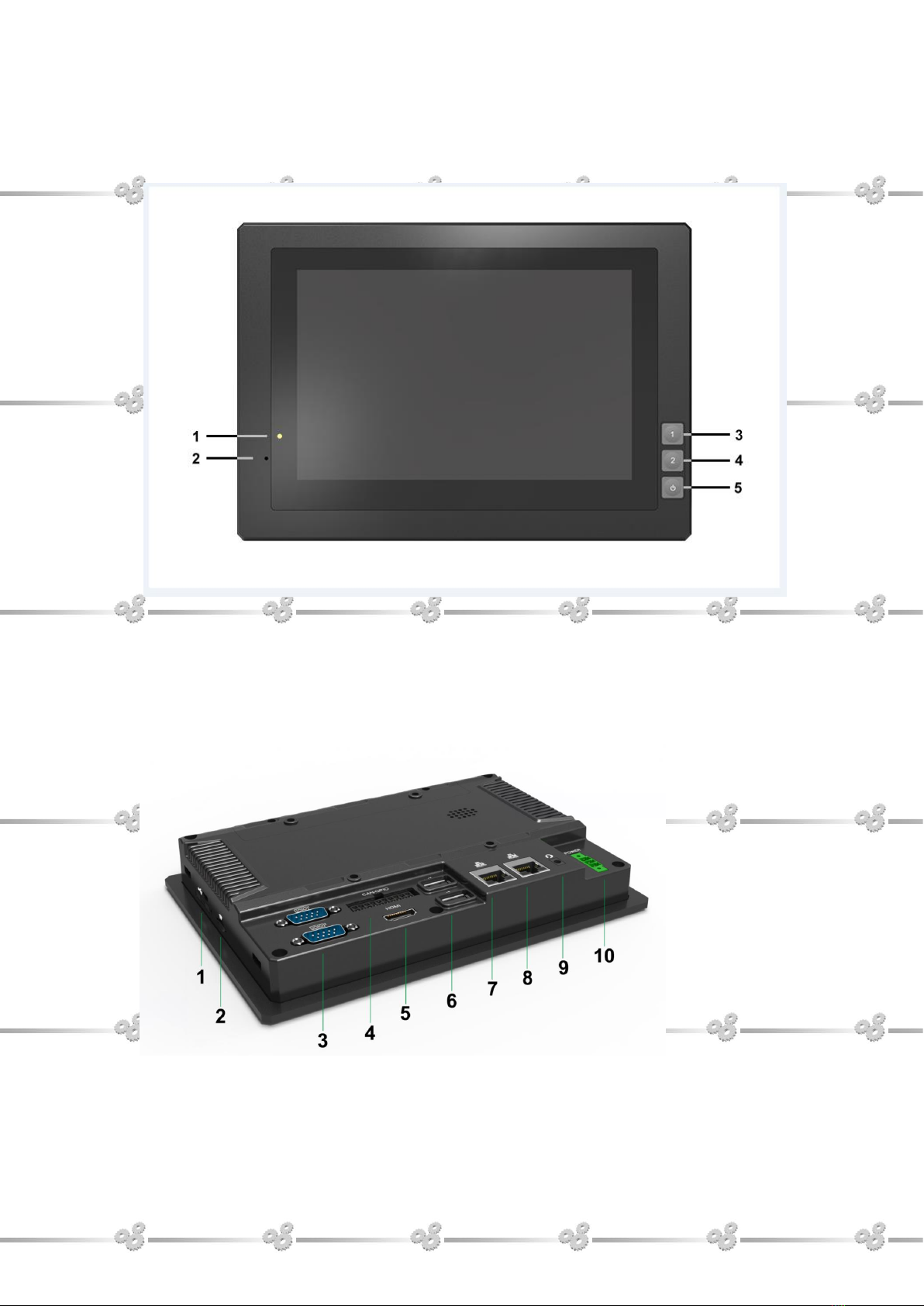
2. Structure Function Explanation........................................................................................6
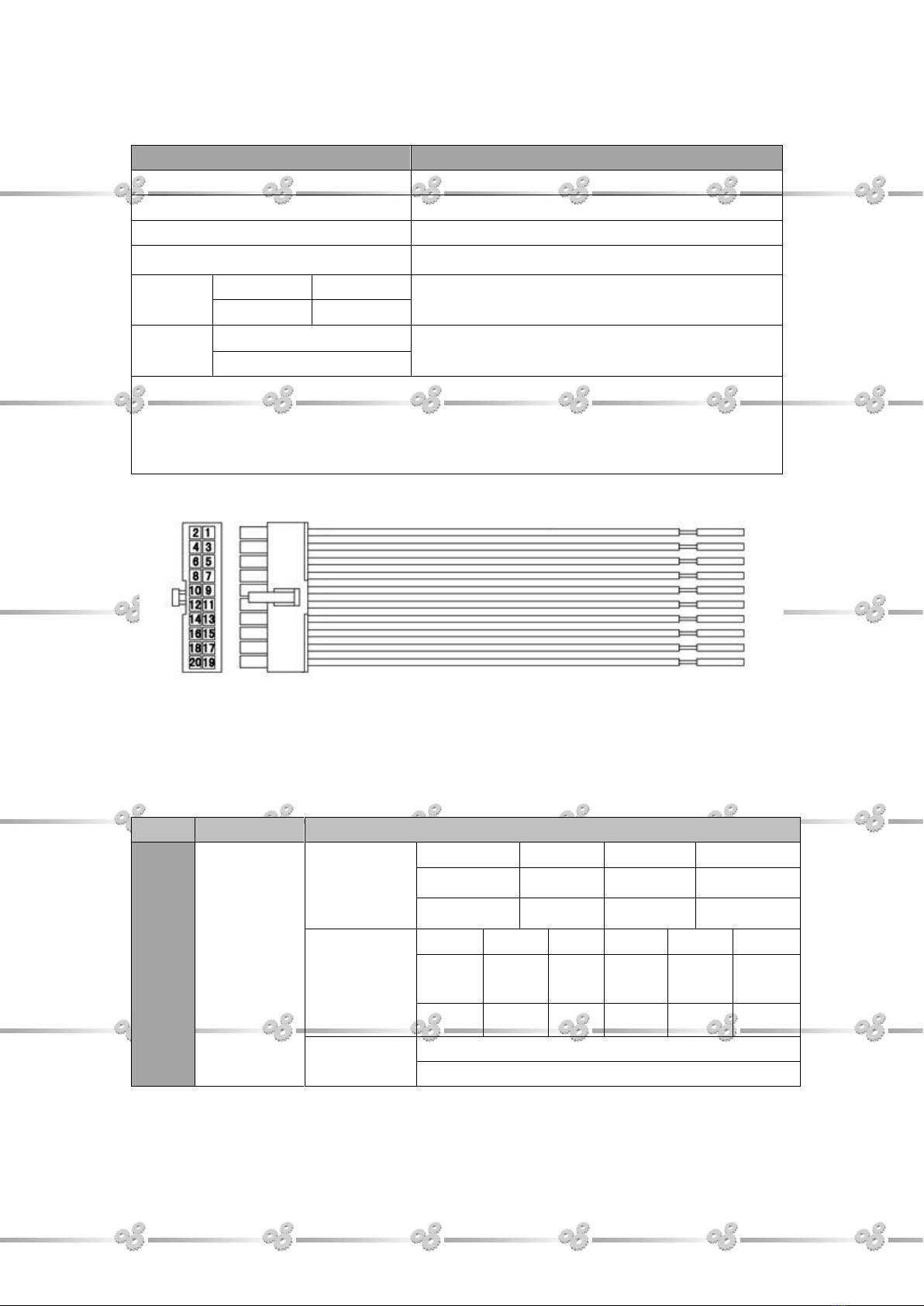
3. Extened Cable Definition.................................................................................................7
3-1 Serial Port................................................................................................................8
3-2 GPIO Interface ......................................................................................................11
4. Memory Card Instruction...............................................................................................12
5. Operation Guide ............................................................................................................12
Basic Operation............................................................................................................12
6. Mounting Methods.........................................................................................................16
7.Accessories....................................................................................................................15
8. Trouble Shooting............................................................................................................18

3
1. Production Description
1.1Brief Introduction
7" 16:10 multi point capacitive touch screen,1280x800 physical resolution.
Intel Atom Z8350 1.44G , 2G DRAM , 32G Emmc, Intel HD Graphic 400;
Windows 10 32-bit;
RS232x4/GPIO(4 input,6 output)/LANx2/USB2.0/USB3.0/HDMI
interface;
Micro SD(TF)card storage,mini SIM card slot.
1.2 Optional Functions
3G/4G (built-in)
Wi-Fi 802.11 b/g/n & Bluetooth 4.0(built-in)
PoE(built-in)
1.3 Basic Parameters
Configuration
Parameters
Display
7″
Touch panel
Capacitive
Physical Resolution
1280×800
Brightness
400cd/m²
Contrast
800:1
Viewing Angle
160°/160°(H/V)
System Hardware
CPU:Intel Atom Z8350 1.44GHz
ROM:32GB Emmc
RAM:2GB LPDDR3

4
GPU:Intel HD Graphic 400
OS:Windows 10 32-bit (Optional)
Interfaces
SIM card
1.8V/2.95V,mini SIM
TF card
1.8V/2.95V, up to 64G
USB
USB host 2.0×2 (support USB 3.0)
GPIO
Input×4, Output×6(See section "3. Extended
Cable Definition" for details.)
HDMI output
HDMIv1.4
LAN
100M×2
Serial Port
COM3 COM4 COM5 COM6
Ear Jack
1
Optional Function
Wi-Fi
802.11a/b/g/n 2.4GHZ
Bluetooth
Bluetooth 4.0 2402MHz~2480MHz
3G/4G
(See section 1.4 for details.)
GPS
External
PoE
25W
Multimedia
Audio
MP3/AAC/AAC+/WAV/FLAC/APE/
AMR/MP4/MOV/F4V…etc.
Video
Encode: 1080p30 H.264 BP/dual 720p
encoding
Decode: 1080p30 + D1
Input Voltage
DC 9~36V
Power Consumption
Overall ≤ 10W
Standby < 5W
Working Temperature
-10℃~50℃
Storage Temperature
-30℃~70℃
Dimension(LWD)
206×144×30.9mm
Weight
790g

5
1.4 3G / 4G Support Parameter & Switch
Band
(Different
versions support
different bands)
Version 1
China/India
FDD LTE: Band 1/Band 3/ Band 8
TDD LTE: Band 38/Band 39 /Band 40/Band
41
DC-HSPA+/HSPA+/HSPA/UMTS: Band
1/Band 5/Band 8/Band 9
TD-SCDMA: Band 34/Band 39
GSM/GPRS/EDGE: 1800 /900
Version 2
EMEA/South America
FDD LTE: Band 1/Band 2 /Band 3/Band 4
/Band 5 /Band 7/Band 8/Band 20
WCDMA/HSDPA/HSUPA/HSPA+: Band
1/Band 2/Band 5/Band 8
GSM/GPRS/EDGE: 850/900/1800/1900
Version 3
North America
LTE: FDD Band 2/Band 4/ Band 5/Band 12
/Band 13/Band 17
WCDMA/HSDPA/HSUPA/HSPA+: Band
2/Band 4/Band 5
Data
Transmission
LTE
LTE-FDD
Max 150Mbps(DL)/Max 50Mbps(UL)
LTE-FDD
Max 130Mbps(DL)/Max 35Mbps(UL)
DC-HSPA+
Max 42 Mbps(DL)/Max 5.76Mbps(UL)
WCDMA
Max 384Kbps(DL)/Max 384Kbps(UL)
TD-SCDMA
Max 4.2 Mbps(DL)/Max2.2Mbps(UL)
EDGE
Max 236.8Kbps(DL)/Max 236.8Kbps(UL)
GPRS
Max 85.6Kbps(DL)/Max 85.6Kbps(UL)

6
2. Structure Function Explanation
1. Power indicator
2. Reset & burn button
3. User-definable button1 (F1)
4. User-definable button2 (F2)
5. Power on/off button
1. Mini SIM card slot.
2. Micro SD slot
3. IOIO 1: (RS232 standard interface, connecting with DB9 standard cable to
convert to 3×RS232 ports).
IOIO 2: (RS232 standard interface, connecting with DB9 optional cable to

7
convert to 1×RS232, 1×RS422 and 1×RS485 ports).
4. GPIO (For extended cable definition, please refer to "3. Extended Cable
Definition").
5. HDMI output.
6. USB Host×2.
7. 100M LAN.
8. 100M LAN, POE function for optional.
9. Ear jack.
10. Power interface.
3. Extended Cable Definition

8
GPIO
Item
Definition
Com 3 RS232
COM3
Com 4 RS232
COM4
Com 5 RS232
COM5
COM 6 RS232
COM6
RS422
Red A
White Z
COM5
Black B
Green Y
RS485
Red Positive Pole
COM6
Black Negative Pole
Note: RS232 and RS422 are alternative for COM5.
RS232 and RS485 are alternative for COM6.
It should match with standard cable when using IOIO 1; Otherwise there is a risk of
short circuit.
No.
Item
Definition
1
Gpio
Interface
Gpio Input
2
4
6
8
Gpio_57
Gpio_82
Gpio_87
Gpio_92
Yellow
Yellow
Yellow
Yellow
Gpio Output
10
12
1
3
5
7
Gpio_
93
Gpio_
191
Gpio
_9
Gpio
_171
Gpio_
174
Gpio_
175
Blue
Blue
Blue
Blue
Blue
Blue
Gpio GND
13
Black

9
3-1 Serial Port
The COM port serial will change bases on the installation order of the 3G/4G device and
the FTDI USB serial port device, which affect the serial port access of RS485/RS422.
The following figure shows the serial port identifier after installing the 3G/4G driver first
and then installing the USB serial port driver.
COM7/COM8/COM9/COM10 show as USB Serial Port.
COM3/COM4/COM5/COM6 show as Quectel USB AT Port (3G/4G serial port). COM6 is
Modem data serial port.
The following figure shows the serial port identifier after installing the USB serial port
driver first and then installing the 3G/4G device.
COM3/COM4/COM5/COM6 show as USB Serial Port.
COM7/COM8/COM9/COM10 show as Quectel USB AT Port (3G/4G serial port). COM10
is Modem data serial port.

10

11
3-2 GPIO Interface
1. GPIO interface as shown below.
(GPIO0-GPIO3 is input port,GPIO4-GPIO9 is output port.)
For the implement and assess method, please see "GPIOTest demo " in CD coming
with the device for details.

12
4. Memory Card Instructions
The memory card and the card slot on the device are precision electronic
components. Please align to the position accurately when inserting the memory card
into the card slot to avoid of damage. Please slightly push the upper edge of the card
to loosen it when removing the memory card, then pull it out.
It is normal when the memory card getting hot after long time working.
The data stored on the memory card may be damaged if the card is not used correctly,
even the power is cut off or the card is pulled out when reading data.
Please store the memory card in packing box or bag if not used for a long time.
Do NOT insert the memory card by force to avoid of damage.
5. Operation Guide
Basic Operation
Soft keyboard
Figure1

13
Network settings: Network Connections shown as Figure2. Make sure the MAC
address shown on the screen should be match with the one labeled on the rear of
device as the device has two LAN ports.
Figure 2
Wi-Fi connection shown as Figure 3
Figure 3

14
Application of SIM Card (Please note the device should be restarted after SIM card
inserted) shown as Figure 4.
Figure 4
Browser shown as Figure 5.
Figure 5
Application of Bluetooth:Bluetooth Manager shown as Figure 6.

15
Figure 6
Multimedia shown as Figure 7
Figure 7

16
Brightness settings shown as Figure 8.
Figure 8
6. Mounting Methods
VESA 75mm rail slot
Embedded mount

17
7. Accessories
Standard Accessories:
1. DC12V adapter-----------------------------------------------------------------1piece
2. GPIO cable----------------------------------------------------------------------1piece
3. DB9 cable(RS232x3)------------------------------------------------------1piece
4. CD drive--------------------------------------------------------------------------1piece
5. Fixed screw--------------------------------------------------------------------- 4pieces
6. User Manual---------------------------------------------------------------------1copy
Optional accessories:
1. DB9 cable(RS232x1,RS485,RS422)------------------------------1piece
2. Micro TF Card-------------------------------------------------------------------1piece
3. 75mm VESA rail slot-----------------------------------------------------------1piece

18
8. Trouble Shootings
Power Problem
Cannot boot up
1. Wrong cable connection
Connect Extended cable with device first, and connect the AC end of DC adapter
with DC input port of Extended cable, then the other end of DC adapter connect
with power plug socket.
2. Bad connection
Check every connection and socket of power source.
Screen Problem
1. No picture on screen.
2. The application reaction time is too long and cannot be activated when clicked.
3. The image appears delay or still when switching.
Please restart your system if the device has any problem as described above.
4. Display screen is misty
Please check whether the display screen surface has dust filth or not. Please
simply wipe with clean and soft cloth.
5. HDMI problem
Incorrect responding to the touch click on screen when connect with HDMI.
It is recommended to operate with mouse, the incorrect responding can’t
calibrate at present.
Note: Due to constant effort to improve products and product features,
specifications may change without notice.

19
Table of contents
Other Lilliput Industrial PC manuals