Witeg LABMAX OE User manual

Version 06042009
witeg Labortechnik GmbH
Am Bildacker 16
D-97866 Wertheim/Main
Phone: +49 (0)9342 / 9301-0
Fax: +49 (0)9342 / 9301-77
www.witeg.de
Version 06042009
Operating Manual
for Dispenser
max
“OE”
“OE S”
“OE HF”
Please study carefully and
follow step by step!

Version 06042009
Table of contents
1 Safety- and user precautions........................................1
1.1 General safety precautions ............................................. 1
1.2 To be considered before initial operation ...................... 2
1.3 Warranty............................................................................ 2
1.4 Operating limitations........................................................ 2
2 General product description.........................................3
3 Preparations...................................................................3
4 Functional characteristics.............................................4
4.1 Air purging........................................................................ 4
4.2 Volume adjustment........................................................... 4
4.3 Dispensing........................................................................ 4
4.4 Safety-Lock....................................................................... 4
5 Cleaning and maintenance............................................5
5.1 Description of the components....................................... 5
5.2 Cleaning ............................................................................ 7
5.3 Sterilization....................................................................... 7
5.4 Disassembly ..................................................................... 8
5.5 Assembly........................................................................... 8
5.6 Avoid clogging.................................................................. 9
6 Spare parts....................................................................10
7 Optional accessories...................................................12
Technical modifications reserved
1
1 Safety- and user precautions
1.1 General safety precautions
In order to put the device into operation as quickly as possible and free from
defects, it is imperative that you read this manual carefully before using this
device.
Highest safety precautions should be used when dispensing corrosive,
poisonous, radioactive or hazardous chemicals.
- Observe the general safety regulations for handling chemicals
(e.g. protective clothing, protective goggles).
- Use the Labmax only regarding to the resistance of materials and for the
purpose for which is intended.
- Always check the device for leaks, fixed screw fittings and a firm position of
the plug and socket connection (e.g. check hoses, cannulas etc. prior to
operation) before you use it.
- Never use force. Breakage of any part will lead to hazardous exposure for
the user as well as for other persons.
- Clean the device every day.
- The user is responsible for checking that the device is suitable for his
application.
- The proper and secure function is only warranted in connection with the
supplied ejection cannula (6). Do not use any other ejection cannula.
- Never use damaged or deformed cannulas.
- The ejection cannula (6) should never face the user and a collection vessel
should be placed underneath.
- If the valve is faulty the cannula might drop.
- Check all screw fittings approximately one hour after each assembling or
disassembling if they are fitting tightly, because leakages might occur due
to material expansion conditional to temperature variations.
- If unsure about dispensing a specific solution, please contact your dealer.

2
1.2 To be considered before initial operation
- Check that the device has not been damaged in transit.
- Push cannula on tightly.
- Do not carry the device at the outer housing (2).
- Push ejection cannula (6) on tightly and slide the cannula holder (7)
into the formed grooves.
- When screwing on the bottle do not grip the device at its outer
housing (2).
- Do not pump before the device has been assembled completely and
a collecting vessel has been placed underneath.
1.3 Warranty
witeg warrantees the Labmax you have received is free of defects in material
and workmanship for 12 months from the date of purchase. witeg´s
responsibility is limited to the repair or replacement of the Labmax.
This warranty is valid only if the Labmax is used in the manner described in this
manual and for the purpose for which it is designed.
witeg is not responsible for consequential damages resulting from the misuse of
this equipment.
1.4 Operating limitations
Labmax “OE” Labmax “OE S” Labmax “OE HF”
Use for nearly all liquids PTFE swelling
solvents hydrofluoric acid
PTFE swelling
Solvents,
hydrofluoric acid hydrofluoric acid PTFE swelling
solvents
solutions which contains any form of solids
Don´t use for
solutions of substances catalysed by platinum-iridium alloys
The temperature of the Labmax “OE” and reagent should not exceed 40 °C
(104 °F).
3
21
20
2 General product description
The Labmax “OE” is witeg´s economy dispenser and consists of high precision
components and extreme solid materials “made in Germany”. This ensures
highest reproducibility during the complete long life cycle of the device.
The Labmax “OE” is fully autoclavable at 121 °C and can be completely
disassembled for cleaning. The zero point is part of the construction and
automatically calibrated after assembling.
Each device is single tested and delivered with conformity certificate.
The air-purging is managed through the ejection cannula and therefore no air
bubbles get into the bottle and a contamination of the bottles content with
previous used chemicals is not possible.
The Labmax “OE” has the witeg´s typical Safety-Lock for your safety at work.
Turn the cannula 180 ° to drain it and avoid further uncontrolled flow of liquid.
3 Preparations
First push the ejection cannula into the
valve and then slide the cannula holder
from above into the groove. Make sure it
fits tightly!
Push the return tube (21) into the big socket and the suction
tube (20) into the small socket.
Control the length of the suction tube and make sure it fits
tightly!
Now you can screw the Labmax “OE” onto the bottle.
((20) and (21) are one tube at the Labmax “OE“ 250 ml)

4
Safety Lock
Dispensing position
4 Functional characteristics
4.1 Air purging
Before starting to pump, it is essential to place a collecting
vessel under the cannula. The valve axle has to be in the
dispensing position (arrow up).
Now perform short pumping movements until no air
bubbles are leaving the cannula. Perform regular and
smooth movements and make sure that the outer housing
(2) is always pushed all the way down.
4.2 Volume adjustment
The quick-volume-adjustment is performed with the volume rocker switch (3).
To set the required dispensing quantity, hold the rocker switch pressed and
move the arrow to the desired volume. Now unhand the rocker and make sure it
fits correctly into the sprockets. (For Labmax 100 ml and 250 ml: turn
adjustment screw counterclockwise until the arrow is easy to move, choose
your desired volume and then fix the adjustment screw.)
4.3 Dispensing
Avoid personal injury from chemicals. To protect your self wear eye protection
and use appropriate safety equipment and clothing.
Please follow all safety instructions and observe operating procedures.
Raise the outer housing (2) until it stops at the point set by the volume rocker
switch. The set quantity will be dispensed into the collecting vessel by pressing
down the outer housing (2) to the lowest point. The movements should be
smooth and constant to achieve an exact ejection volume.
4.4 Safety-Lock
Turn the cannula to the left stop (arrow down).
The liquid into the cannula will now rinse back into the bottle.
Any further dispensing of liquid is not possible.
5
5 Cleaning and maintenance
5.1 Description of the components
Volume rocker
switch (3)
Fix screw (1)
Adaptor ring (4)
Outer housing (2)
Cap nut (5)
Cannula holder (7)
Ejection cannula (6)
Valve head (19)
Return tube (21) Suction tube (20)
Adaptor ring (4)
Cylinder (18)
Cap nut (5)
Cylinder Set (16)
Plunger (17)
Ejection valve (11)
Suction valve (8)
Valve star (9)
Valve ball (10)
edges on top!

6
Closing cap (13)
O-Ring a (14 a)
Valve axle (12)
O-Ring b (14 b)
Components of Labmax “OE” 250 ml
Ejection valve (11)
Suction valve (8)
Valve ball (10)
Glass spring (22)
ball on top!
Fixing bolt (23)
Plunger (17)
Gray thread adaptor (25)
Blue thread adaptor (24)
Cannula holder (7)
Ejection cannula (6)
Valve head (19)
Outer housing (2)
Volume adjustment screw (3)
Valve axle (12)
7
5.2 Cleaning
Cleaning is necessary if you want to use the Labmax for another chemical or if
you don’t want to use it for a longer time.
1. Follow the safety instructions!
2. Push the plunger downwards until it stops and then turn the
valve axle (12) to the left stop (Safety-Lock).
3. Let the remaining reagent in the ejection tube (6) flow back into the
reagent bottle.
4. Place the device with the bottle into a suitable sink.
5. Unscrew the device from the bottle and slightly tap the inside of the
bottle with the suction tube (20) in order to drain it.
6. Rinse the Labmax “OE” with distilled water or alcohol
Disassemble the Labmax until you can surely clean it from all reagents.
Sometimes it could last out to rinse the device.
The cleaning can be performed with distilled water or alcohol.
The Labmax should be rinsed daily if used with the following chemicals:
- Solid forming solution
- Inorganic oxidizing solutions (i.e. biuret reagent)
5.3 Sterilization
After removal of return tube (21) and the suction tube (20) the
Labmax “OE” can be steam-sterilized (121 °C, 2 bar).
Place the device on a cloth and avoid any contacts with hot metal surfaces.
In order to prevent a de-adjustment due to the heat expansion of the different
materials, the volume rocker switch (3) has to be set to minimum 2/10 of its
maximum volume.
After sterilization let the device cool down to room temperature before you use it
again. After each sterilization check all parts for deformations or other changes.
After approximately one hour, check all screw fittings once again for a tight fit.
Do not use any deformed or leaking parts.
It is also possible to perform a chemical sterilization with alcohol, formaldehyde
etc.
In case of deformation please return the device including the autoclave
protocols.

8
5.4 Disassembly
1. Follow the safety instructions!
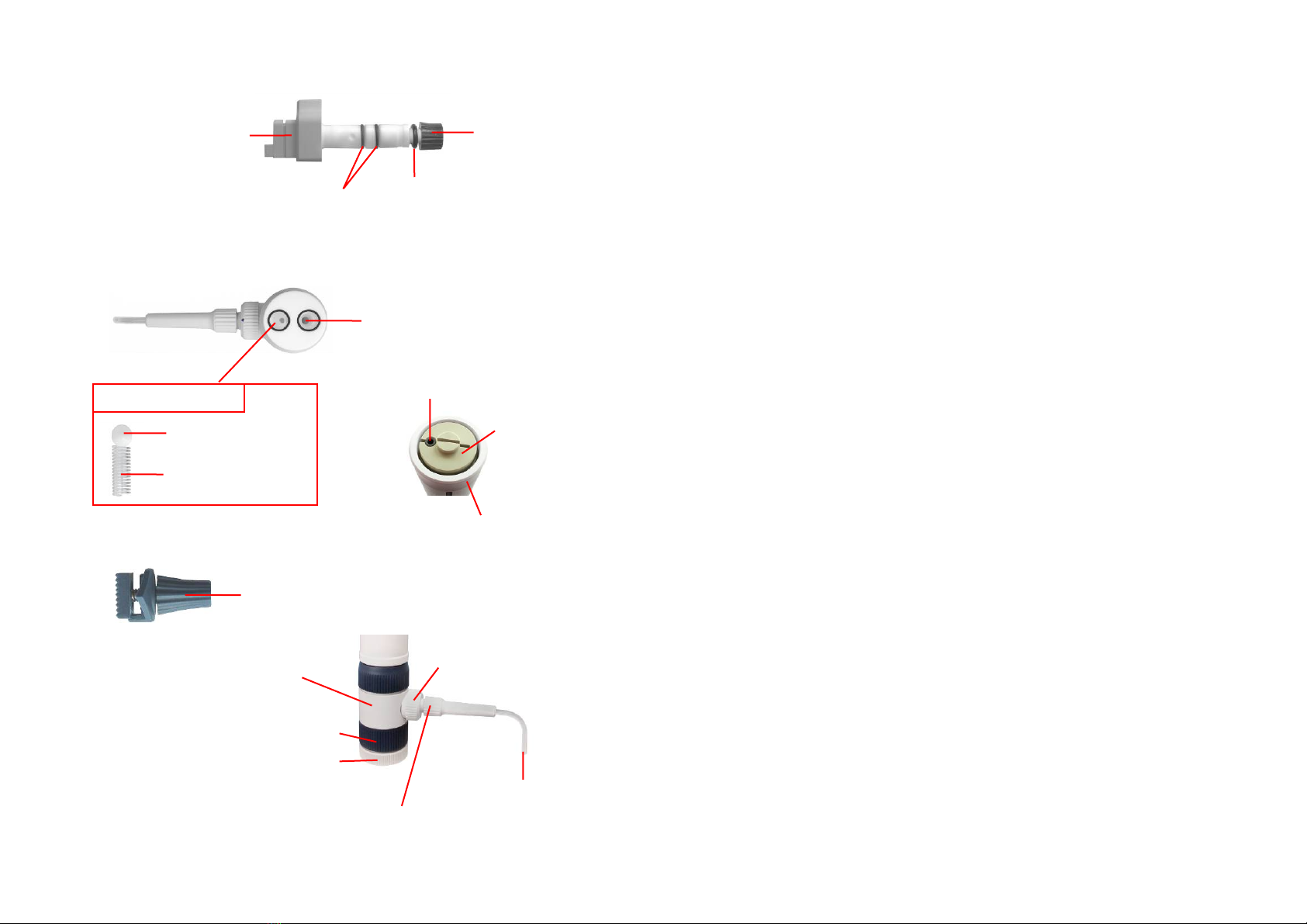
2. Push the outer housing (2) down until it stops and then turn the valve
axle (12) to the left stop (Safety-Lock).
3. Let the remaining reagent in the ejection cannula (6) flow back into the
reagent bottle.
4. Place the device with the bottle into a suitable sink.
5. Unscrew the device from the bottle and carefully tap with the suction tube
(20) from the inside against the bottle, so that it is drained as well.
6. Rinse the Labmax “OE” with distilled water or alcohol.
7. Remove the suction tube (20) and the return tube (21).
8. Remove the cannula holder (7) and then the cannula (6).
9. Loosen the fix screw (1).
10. Pull the plunger (17) out of the cylinder (18). Make one pump movement
before. Then the plunger (17) can be handled easier.
(For Labmax 250 ml: before you can screw out the plunger, you have to
loosen the fixing bolt with standard 5 mm Allen key.)
11. Press down the Volume rocker switch (3) and pull it out of the slot.
(For Labmax 100 ml and 250 ml: Loosen the fix screw and the arrow).
12. Remove the outer housing (2).
13. Loosen the cap nut (5).
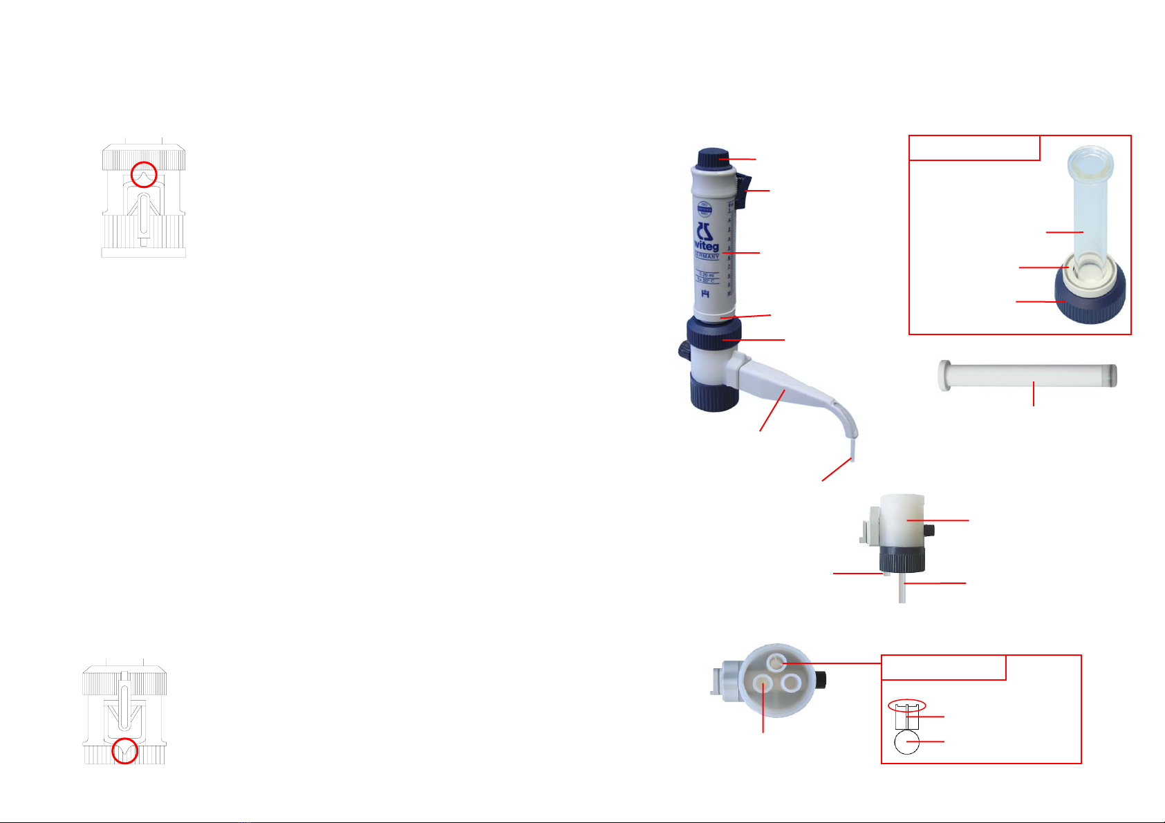
14. Pull the cylinder set (16) out of the valve head (19), keep in mind that the
valve star (9) and the valve ball (10) might fall out.
15. Take the valve star (9) and the valve ball (10) out of the valve head.
16. Loosen the closing cap (13) and remove the O-ring a (14 a).
(This point is not applicable for Labmax 250 ml)
17. Pull the valve axle (12) out of the valve head (19).
5.5 Assembly
1. Push the valve axle (12) into the valve head (19).
2. Assemble the O-ring a (14 a) and the closing cap (13).
(This point is not applicable for Labmax 250 ml.)
3. Place the valve ball (10) and the valve star (9) into the suction valve.
Check that the spikes of the valve star (9) point upwards.
(For Labmax 250 ml: Place one valve ball (10) in the suction valve.
Place the glass spring (22) and the other ball into the ejection valve).
4. Assemble the cylinder set (16) ontthe valve head (19). Check that the
notches of the cylinder set (16) are placed exactly over the domes of
the valve head (19).
5. Tighten the glass cylinder (18) with the cap nut (5). Check that all parts
fit tightly.
6. Slide the outer housing (2) on the cylinder (18).
9
7. Place the device horizontally and mount the volume rocker switch into
the slot. Than clip the adaptor ring (4) onto the outer housing (2).
For Labmax 100 ml and 250 ml:
8. Erect the device and push the plunger (17) into the cylinder (18) until it
stops. If there is an adaptor ring, make sure it is between plunger and
outer housing before.
9. Screw the fix screw (1) into the outer housing (2).
10. Push the ejection cannula (6) into the valve axle (12) and fix it with the
cannula holder (7).
11. Push the return tube (21) and the suction tube (20) into the valve head
(19).
12. Screw the device on the reagent bottle.
5.6 Avoid clogging
When the Labmax is screwed open, make sure that the valves are always
surrounded by liquid.
You can keep the dispenser smooth-running by rinsing it with distilled water or
alcohol.
Unfix clogged valves with a thin object (wire, paperclip etc.). Therefore stick it
from upper side into the suction valve and from below side into the suction
valve.
Make sure that you clean the valves completely after unfixing otherwise they
may leaking in fact of incrustations.
Step 1 Step 2 Step 3 Step 4 Step 5

10
6 Spare parts
Part Size Article no. Only fo
r
version
Fix screw (1) 2,5 - 10 ml 5.370.251
10 - 100 ml 5.370.252
250 ml 5.370.253
Outer housing (2) 2,5 ml 5.370.170 “OE”
5 ml 5.370.171 “OE”
10 ml 5.370.172 “OE”
25 ml 5.370.173 “OE”
50 ml 5.370.174 “OE”
100 ml 5.370.175 “OE”
250 ml 5.370.176 “OE”
10 ml 5.370.172 S “OE S”
25 ml 5.370.173 S “OE S”
50 ml 5.370.174 S “OE S”
10 ml 5.370.172 HF “OE HF”
25 ml 5.370.173 HF “OE HF”
Volume rocker switch (3) 2,5 - 10 ml 5.370.151-1
25 - 50 ml 5.370.151-2
100 ml 5.370.151-3
250 ml 5.370.151-4
Ejection cannula (6) 2,5 -10 ml 5.375.0031
25 - 100 ml 5.375.0041
250 ml 5.375.008
Cannula holder (7) 2,5 - 10 ml 5.375.005
25 - 100 ml 5.375.006
250 ml 5.375.007
Valve star (9) 2,5 & 5 ml 5.370.377
10 - 100 ml 5.370.378
Valve ball (10) 2,5 & 5 ml 5.370.373 “OE”, “OE S”
10 - 100 ml 5.370.374 “OE”, “OE S”
250 ml 5.370.374 5
10 ml 5.370.368 “OE HF”
25 ml 5.370.370 “OE HF”
Valve axle (12) 2,5 & 5 ml 5.370.200
10 - 100 ml 5.370.201
250 ml 5.370.364 W
Closing cap (13) 2,5 - 100 ml 5.370.380
11
O-Ring a (14 a) 2,5 - 100 ml 5.370.381
O-Ring b (14 b) 2,5 - 10 ml 5.370.387
Cylinder set (16) 2,5 ml 5.370.255 “OE”
(includes 4, 5, 18) 5 ml 5.370.256 “OE”
10 ml 5.370.257 “OE”
25 ml 5.370.258 “OE”
50 ml 5.370.259 “OE”
100 ml 5.370.260 “OE”
250 ml 5.370.261
10 ml 5.370.257 S “OE S”
25 ml 5.370.258 S “OE S”
50 ml 5.370.259 S “OE S”
10 ml 5.370.167 “OE HF”
25 ml 5.370.168 “OE HF”
Plunger (17) 2,5 ml 5.370.102 “OE”
5 ml 5.370.105 “OE”
10 ml 5.370.110 “OE”, “OE HF”
25 ml 5.370.125 “OE”, “OE HF”
50 ml 5.370.150 “OE”
100 ml 5.370.101 “OE”
250 ml 5.370.107
10 ml 5.374.110 “OE S”
25 ml 5.374.125 “OE S”
50 ml 5.374.150 “OE S”
Valve head (19) -set-
(incl. 9, 10, 12, 13, 14 a) 2,5 - 10 ml 5.370.360
(incl. 9, 10, 12, 13, 14 a) 10 - 100 ml 5.370.361
(incl. 10, 22, 12,22, 23 24, 25) 250 ml 5.370.364
Suction tube (20) 310 mm 2,5 & 5 ml 5.375.000 N 310
10 - 100 ml 5.375.001 310
Suction tube (20) 390 mm 2,5 & 5 ml 5.375.000 N 390
10 - 100 ml 5.375.001 390
250 ml 5.375.009
Return tube (21) 2,5 & 5 ml 5.375.000 N 40
10 - 100 ml 5.375.001 40
Glass Spring (22) 250 ml 5.370.383
Fixing bolt (23) 250 ml 5.370.125.252
Blue thread adaptor (24) 250 ml 5.377.250 B
Grey thread adaptor (25) 250 ml 5.377.250 G

12
7 Optional accessories
1. Borosilicate glass one-way valve with
plastic coating, avoids emitting of gases
and strong smells
Article-No. 5.377.300
2. Borosilicate glass tube with plastic coating
for calcium chloride, ensures dry
atmosphere in storage vessel
Article-No. 5.377.310
3. Filter against dust and bacteria in storage
vessel
pore size 2 µm / 4,5 µm
Article-No. 8.214.002 / 8.214.001
4. Spare adapters
GL 45/32 : Art. No. 5.497.600
GL 45/32 : Art. No. 5.377.045
GL 38/32 : Art. No. 5.377.038
GL 28/32 : Art. No. 5.377.028
GL 25/32 : Art. No. 5.377.025
This manual suits for next models
2
Table of contents
Other Witeg Dispenser manuals