Site this appliance beneath an extraction canopy for the removal of combustion
products.
When making the gas connection, fit an isolating cock into the supply line close to
the appliance for emergency shutdown or servicing purposes.
Installation must include sufficient ventilation to prevent the occurrence of
unacceptable concentrations of substances harmful to health in the room of
installation. There must be a minimum free area of 4.5cm2per kW of total heat
input.
Allow for a sufficient flow of fresh air for complete gas combustion.
Do not connect directly to any flue, ducting or mechanical extraction system.
The gas supply hose or tubing shall comply with national requirements in force and
shall be periodically examined and replaced as necessary. If flexible hose is used,
secure the appliance to the wall with a chain.
Install this appliance on a level surface ensuring all vents are unobstructed. Any
partitions, walls or furniture must be of non-combustible material.
Gas supply and connection
Check that the gas supply corresponds to that specified on the data plate.
Connection is at the rear of the unit via a ½ G female thread. The gas supply tubing
or hose shall comply with the national requirements in force and shall be
periodically examined and replaced as necessary.
An isolating cock should be fitted into the supply line close to the unit for emergency
shutdown or servicing purposes.
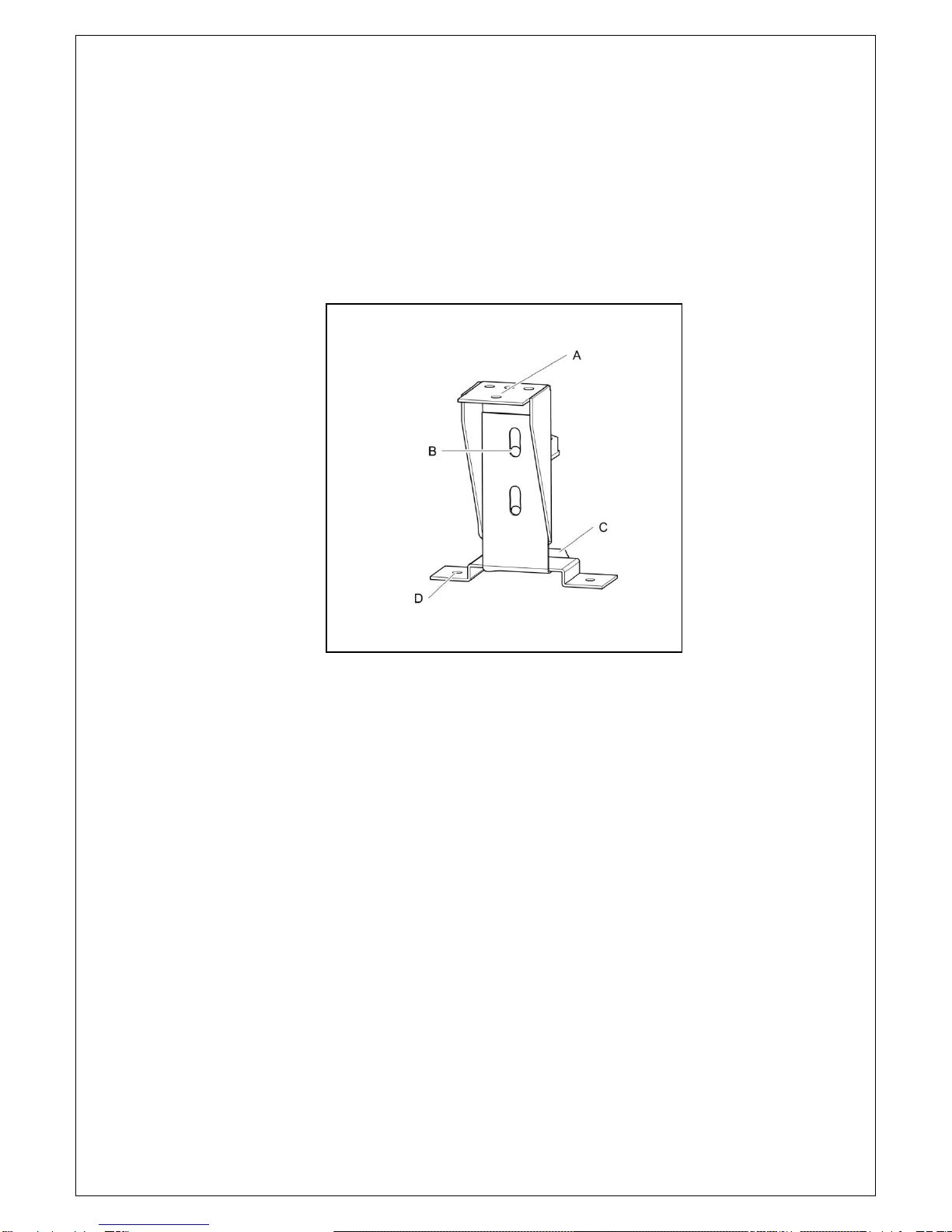
Fitting the Stabilising Kit (Fig 1)
The stabilising kit must be fitted to prevent accidental toppling of the appliance and
to ensure a safe working environment.
Fit the adjustable stabiliser centrally to the underside of the front cross member of
the appliance (A) using the M5 x 16 hex screws and shake proof washers provided.
Ensure the tongue of the bracket is facing rearward and adjusted to sit just off the
floor(C).