· Line Seiki predetermining counters-highly reliable and
extremely versatile.
· Large , high-brightness LED’s.
· Protected against accidental Tripping of output relay.
· Fits DIN panel opening.
· Built-in power supply module.
· Switch or pulse input and output.
· Two operating modes, instantaneous reset or overrun.
· Memory circuit stores count data during power failures.
· Dustproof thumbwheel switches.
FEATURES
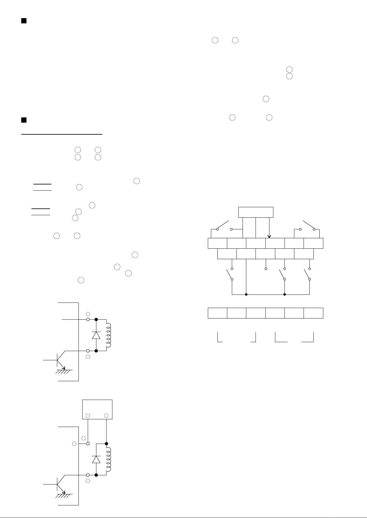
CONNECTIONS
See diagram for location of terminals
1. Power Supply
· 115 VAC - Terminal and
· 230 VAC - Terminal and
2. Input
a) Pulse
Positive, regulated 4.5 VDC to 27 VDC - Terminal
Negative - Terminal
b) Proximity Sensor ( 12VDC )
Positive 12 VDC - Terminal
Negative - Terminal
Output - Terminal
c) Switch
Terminal and
3. Output
a) Pulse ( 45 VDC at 100mA maximum ) - Terminal
b) Switch ( 230 VAC , 4A ; resistive load )
N. C. ( closed during count ) - Terminal
N. O. ( closed at present number ) - Terminal
COMMON - Terminal
16 17
4
4
15 17
3
2
2
9
14
13
12
1
3
BUILT - IN POWER SUPPLY
CONNECTIONS
12 VDC
Relay
2
9
EXTERNAL POWER SUPPLY
5 - 30 VDC
Relay
5 - 30 VDC
Power Source
8
+
-
-
9
4. Remote Reset
Terminal and
( Counter can be reset by conventional switch, relay or microswitch. )
5. Output Time
0.2 second - no connection to negative of supply
1.0 second - negative of supply - Terminal
Indefinite - negative of supply - Terminal
6. Operating Mode
Instantaneous Reset Type : no connection required.
Overrun Type : Terminal , connect to negative of supply.
7. Memory
Connect Terminal to Terminal on MD-144M or MD-122M
NOTE : Disconnect wiring to prevent battery discharge when the counter is
out of service for more than 1,000 hours. Battery is charged whenever power
is being supplied. The LED display is extinguished while MD-144M or
MD-122M is used on power failure, and the counter will not operate even
if input signal or reset signal is received.
( input signals do not consume battery energy. )
8. CAUTION
Switch input and proximity-sensor input cannot be used at the same time.
Do not apply voltage to switch input terminals or remote-reset terminals.
56
10
11
11
7 3
1
12
7 8 9 10 11
2
13
3
14
4
15
5
16
6
17
Sensor
Signal
Open
Collector
Output
Memory
Type Only
Output
1 second
Output
Latched
until
reset
Remote ResetSwitch Input
GND
GNDMemory
GND+ 12V
(
(
(
(
COM. N. 0. N. C. 230 115 0 V
Relay Output AC


