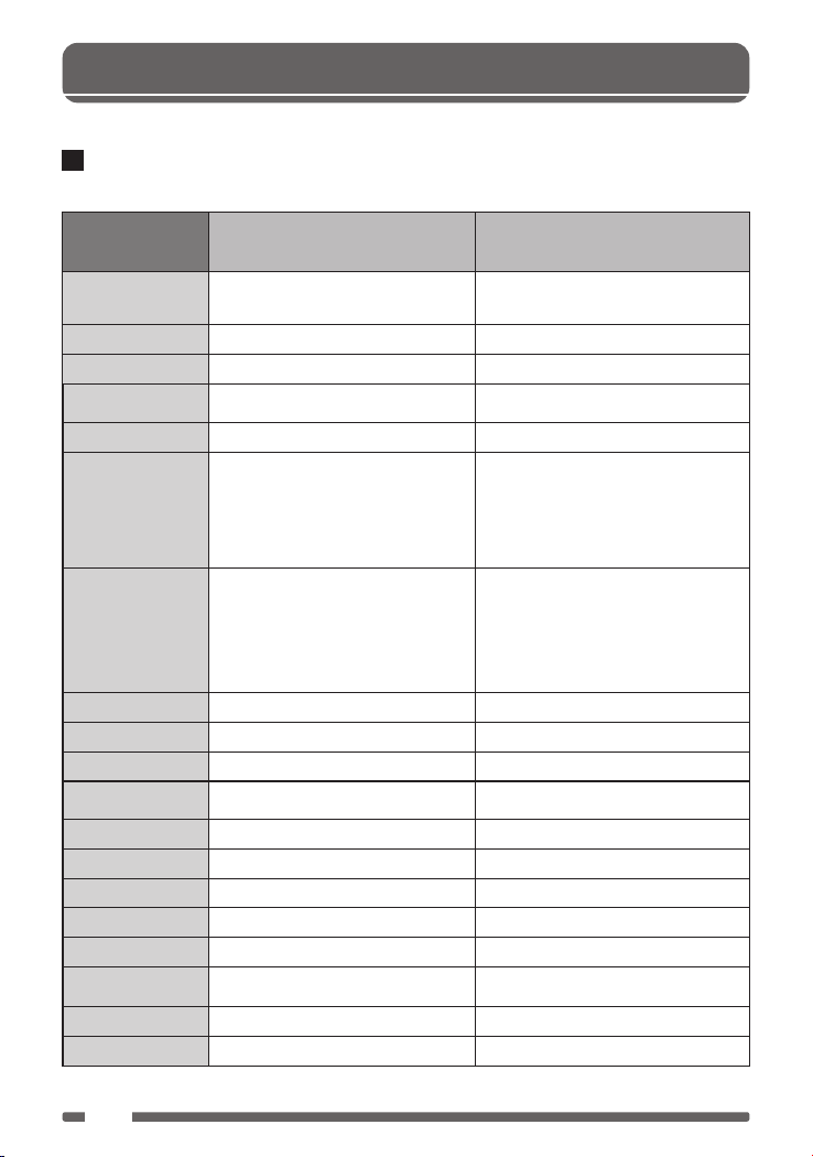
Performance and indicators:
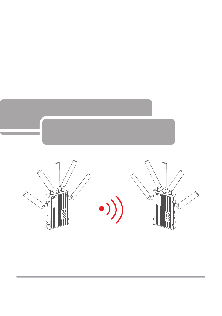
Transmitter Receiver
HDMI Input(Type A Female); 5 x Antenna
port(RP-SMA male); DC input; mini USB interface
HDMI Output (Type A female); 5 x Antenna
port(RP-SMA male); DC input; mini USB interface
7-36V DC 7-36V DC
<8.6W <7.5W
(L x W x H): 148x 90 x 20.5mm, exclude antennas
and battery buckle
(L x W x H): 148x 90 x 20.5mm, exclude antennas
and battery buckle
379g 349g
HDMI:1080p(60/59/50/30/25/24Hz);
1080i(60/59/50Hz);720p(60/59/50Hz);
576p(50Hz); 480p(60/59Hz)
Panel:1920x1080,1768x992,1366x768,1280x768,128
0x720,1280x600,1176x664,1024x768,800x600,720x
576,720x480
/
/
I2S;PCM;SPDIF;AC-3;DTS;Dolby 5.1/7 /
I2S;PCM;SPDIF;AC-3;DTS;Dolby 5.1/7
/
Link-Green; Video-Yellow
OFDM 16QAM
Wireless RSSI-Blue (4 LEDs);Video-Yellow
5.1-5.9GHz,configurable with China, North
American, Europe, etc
5.1-5.9GHz,configurable with China,
North American, Europe, etc
OFDM OOK
Maximum 13dBm Maximum 17dBm
/ -75dBm
20/40MHz 20/40MHz
Point to point
HDMI 1.3 standard;WHDI 1.0 standard;HDCP 1.2
protocols(HDMI 1.4 3D option)
HDMI 1.3 standard;WHDI 1.0 standard;HDCP 1.2
protocols(HDMI 1.4 3D option)
0-40°C(operating condition);-20~60°C(Storage)
FCC; CE. FCC; CE.
Interface
Supply voltage range
Power consumption
Size
Weight
Input Video Format
Output Video Format
Input Audio Format
Output Audio
Signal Indicator
Frequency Band
Modulation Mode
Transmission Power
Receiver Sensitivity
Broadcast mode
Transmission standard
Bandwidth
Temperature Range
Compliance
HDMI:1080p(60/59/50/30/25/24Hz);
1080i(60/59/50Hz);720p(60/59/50Hz);
576p(50Hz); 480p(60/59Hz)
Panel:1920x1080,1768x992,1366x768,1280x768,128
0x720,1280x600,1176x664,1024x768,800x600,720x
576,720x480
4
2
2. About
Point to point
0-40°C(operating condition);-20~60°C(Storage)