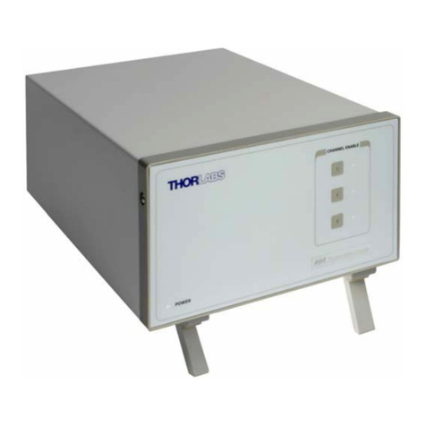
LinMot B1100-PP User manual

Installation Documentation for the following Controllers:
-B1100-PP (-HC, -XC)
-B1100- F (-HC, -XC)
-B1100-GP (-HC, -XC)
Servo Controller Installation Guide
Document version: 3.9.2 / June 2009

Installation Guide B1100
© 2009 NTI AG
This work is protecte by copyright.
Un er the copyright laws, this publication may not be repro uce or transmitte in any form, electronic or mechanical, inclu ing
photocopying, recor ing, microfilm, storing in an information retrieval system, not even for i actical use, or translating, in whole
or in part, without the prior written consent of NTI AG.
LinMot® is a registere tra emark of NTI AG.
Note
The information in this ocumentation reflects the stage of evelopment at the time of press an is therefore without obligation.
NTI AG reserves itself the right to make changes at any time an without notice to reflect further technical a vance or pro uct
improvement.
Document version 3.9.2 / mk / June 2009
Page 2 of 18 Installation Gui e B1100 NTI AG/ LinMot/

Installation Guide B1100
Table of Content
IMPORTANT NOTES FOR B1100 SERIES CONTROLLERS......................................4
SYSTEM O ER IEW.....................................................................................................5
B1100 INTERFACES......................................................................................................6
FUNCTIONALITY............................................................................................................7
SOFTWARE....................................................................................................................7
POWER SUPPLY AND GROUNDING...........................................................................8
DESCRIPTION OF THE CONNECTORS / INTERFACES.............................................9
PHYSICAL DIMENSION...............................................................................................14
POWER SUPPLY REQUIREMENT..............................................................................15
ORDERING INFORMATION.........................................................................................16
INTERNATIONAL CERTIFICATIONS..........................................................................16
DECLARATION OF CONFORMITY CE-MARKING....................................................17
CONTACT ADDRESSES.............................................................................................18
NTI AG, LinMot Installation Gui e B1100 Page 3/18

Installation Guide B1100
Important notes for B1100 series controllers
C A U T I O N !
In order to assure a safe and error free operation, and to avoid severe
damage to system components, all system components must be
directly attached to a single ground bus that is earth or utility
grounded (see chapter Power Supply and Grounding).
Each system component should be tied directly to the ground bus
(star pattern), rather than daisy chaining from component to
component. (LinMot motors are properly grounded through their
power cables when connected to LinMot controllers) (see chapter
Power Supply and Grounding).
All connectors must not be con nected or disconnected while DC
voltage is present. Do not disconnect system components until all
LinMot controllers LEDs have turned off. (Capacitors in the power
supply may not fully discharge for several minutes after input voltage
has been disconnected). Failure to observe these precautions may
result in severe damage to electronic components in LinMot motors
and/or controllers.
Do not switch Power Supply DC oltage. All power supply switching
and E-Stop breaks should be done to the AC supply voltage of the
power supply.
Do not connect or disconnect the motors from controllers with
voltage present. Wait to connect or disconnect motors until all
LinMot controllers LEDs have turned off. (Capacitors may not fully
discharge for several minutes after power has been turned off).
Failure to observe these precautions may result in severe damage to
electronic components in LinMot motors and/or controllers.
Page 4 of 18 Installation Gui e B1100 NTI AG/ LinMot/

Installation Guide B1100
System Overview
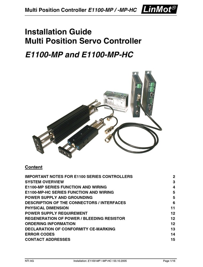
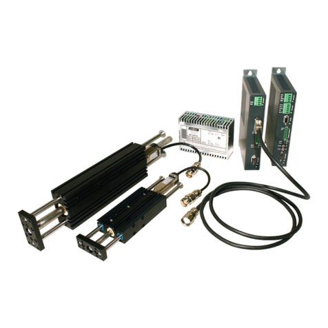
Typical servo system B1100-XX-YY: Servo controller, motor an power supply.
NTI AG, LinMot Installation Gui e B1100 Page 5/18

Installation Guide B1100
B1100 Interfaces
B1100-PP /-HC/-XC
B1100- F /-HC/-XC
B1100-GP /-HC/-XC
Connector
X1 Motor Supply ● ● ●
X2 Motor Phases (Screw Terminals) ● ● ●
X3 Motor / Motor Signals ● ● ●
X5 Com / Config RS232, RS485, CAN ● ● ●
X7 RS485 / CAN In ● ● ●
X8 RS485 / CAN Out ● ● ●
X13 External/Simulate Position Enco er
Diff Hall Switches ● ● ●
X14 6 Digital Inputs
6 Digital Outputs
Analog In 0..10V
Analog In –10V.. +10V
Diff Step Dir zero
24V Logic Supply
● ● ●
LED State In icator ● ● ●
S4 Bus Termination ● ● ●
Page 6 of 18 Installation Gui e B1100 NTI AG/ LinMot/

Installation Guide B1100
Functionality
B1100-PP
B1100-PP-HC
B1100-PP-XC
B1100- F
B1100- F-HC
B1100- F-XC
B1100-GP
B1100-GP-HC
B1100-GP-XC
Supply oltage
Motor Supply 72VDC (24...85VDC) ● ● ● ● ● ● ● ● ●
Logic Supply 24VDC (22...26VDC) ● ● ● ● ● ● ● ● ●
Motor Phase Current
8A peak / 6A rms ● ● ●
15A peak / 9A rms ● ● ●
25A peak / 12A rms ● ● ●
Controllable Motors
LinMot P01-23x… ● ● ● ● ● ● ● ● ●
P01-37x… ● ● ● ● ● ● ● ● ●
P01-48x… ● ● ● ● ● ● ● ● ●
DC Motors ● ● ● ● ● ● ● ● ●
Brushless DC / EC Motors ● ● ● ● ● ● ● ● ●
Command Interface
Easy Steps Max. 6 Comman s ● ● ● ● ● ● ● ● ●
+/-10V Current Comman Interface ● ● ● ● ● ●
Step Direction In exer Interface ● ● ● ● ● ●
Cm Tab IO Interface (X14-IOs) (with EasySteps) ● ● ● ● ● ●
RS232 up to 115.2 kBau ● ● ●
RS485 up to 115.2 kBau ● ● ●
CANOpen up to 1MBau ● ● ●
DeviceNet 125, 250, 500 kBau ● ● ●
External Position Sensor
Incremental RS422 up to 2 MHz ● ● ● ● ● ● ● ● ●
Position Indexer Input
Step Dir Zero/ ABZ RS422 up to 2 MHz ● ● ● ● ● ●
Position Encoder Simulation
AB RS422 up to 2.5 MHz ● ● ● ● ● ●
Configuration
RS232 Configuration ● ● ● ● ● ● ● ● ●
CAN Multi Axes Configuration ● ● ● ● ● ● ● ● ●
Software
The configuration SW LinMotTalk1100 is free of charge an can be ownloa e from our home page.
For fast results see also the quick start gui es an configurations for the B1100-PP an B1100-VF
controllers:
•QuickStartGui e_B1100-PP.p f
•QuickStartGui e_B1100-VF.p f
This quick start gui es are istribute with the LinMotTalk1100 SW.
NTI AG, LinMot Installation Gui e B1100 Page 7/18

Installation Guide B1100
Power Supply and Grounding
*Insi e of the B1100 controller the PWR motor GND an PWR signal GND is connecte together an to
the GND of the controller housing. It is recommen e that the PWR motor GND is NOT groun e at
another place than insi e of the controller to avoi circular currents.
In or er to assure a safe an error free operation, an to avoi severe amage to system
components, all system components* must be well grounded to either a single earth
or utility ground. This inclu es both LinMot an all other control system components to
the same groun bus.
Each system component* shoul be tie irectly to the groun bus (star pattern), rather
than aisy chaining from component to component. (LinMot motors are properly
groun e through their power cables when connecte to LinMot controllers.)
Power supply connectors must not be con nected or disconnected while DC voltage
is present. Do not isconnect system components until all LinMot controllers LEDs have
turne off. (Capacitors in the power supply may not fully ischarge for several minutes
after input voltage has been isconnecte ). Failure to observe these precautions may
result in severe amage to electronic components in LinMot motors an /or controllers.
Do not switch Power Supply DC oltage. All power supply switching an E-Stop
breaks shoul be one to the AC supply voltage of the power supply. Failure to observe
these precautions may result in severe amage to controller.
Page 8 of 18 Installation Gui e B1100 NTI AG/ LinMot/

Installation Guide B1100
Description of the connectors / Interfaces
X1: Motor Supply
Screw Terminals Motor Supply: 72VDC nominal, 24...85VDC
Absolute max. Rating: 72VDC +20%.
External Fuse: 10AT for LC (8Apeak), 16AT for HC an XC (15A/25Apeak) servos.
If motor supply voltage excee s 90VDC, the controller will go into error state.
- Tightening Torque: min 0.4Nm
- Screw Threa : M 2,5
- Use 60/75°C copper con uctors only
- Con uctor Cross-Section 2.5mm2 (AWG14) max Length 4m
X2: Motor Phases
PH1+ /U
PH1- /V
PH2+ /W
PH2-
SCRN
LinMot Motor: 3-phase EC-Motor:
Motor Phase 1+ re Motor Phase U
Motor Phase 1- pink Motor Phase V
Motor Phase 2+ blue Motor Phase W
Motor Phase 2- grey
Shiel
Screw Terminals The motor phases are present at X2 an X3. It is recommen e to use X2. It is only allowe to use X3 for
connecting motor phases if RMS current is below 2A an peak current is below 4A.
Never connect motor phases on X2 an X3!
- Tightening Torque: min 0.4Nm
- Screw Threa : M 2,5
- Con uctor Cross-Section: max. 2.5mm2
- Use 60/75°C copper con uctors only
NTI AG, LinMot Installation Gui e B1100 Page 9/18

Installation Guide B1100
X3: Motor
1
2
3
4
5
6
7
8
9
case
LinMot Motor: 3-phase EC-Motor:
Motor Phase 1+
Motor Phase 2+
+5VDC +5VDC (Hall Supply)
Sensor Sine Hall 1
Temp. In Hall 3
Motor Phase 1-
Motor Phase 2-
AGND AGND (Hall Supply)
Sensor Cosine Hall 2
Shiel
DSUB-9 (f) Note:
Use +5V (X3.3) an AGND (X3.8) only for motor internal hall sensor supply (max. 100mA).
Caution:
Do NOT connect AGND (X3.8) to groun or earth!
It is only allowe to use X3 for connecting the motor phases if RMS current is below 2A an peak current
below 4A.
Motor Wiring for Phase Currents above 2A RMS 4A peak (recommended general wiring)
Important:
If motor phase current excee s 2ARMS or 4Apeak, motor phases must be wire to X2.
Motor wiring for Phase Currents below 2A RMS 4A peak
Page 10 of 18 Installation Gui e B1100 NTI AG/ LinMot/

Installation Guide B1100
Important:
Motor phases may only be connecte to X3 if RMS current is below 2A an peak current is below 4A.
LED: State Display
Green
Re
24V Logic Supply OK
Error (Fatal Error blinking)
S4: Bus Termination
S4 Switch 4: Bootstrap
Switch 3: Termination CAN on/off
Switch 2: Termination RS485 on/off
Switch 1: RS232 (switch “off” / RS485 “on”). Selection for RS232 or RS485
Factory settings: Switch 3 “on”, all other switches “off”
X5: COM
1
2
3
4
5
6
7
8
9
case
RS485_Tx+ Y
RS232_Tx
RS232_Rx
RS485_Rx+ A
GND
RS485_Rx- B
RS485_Tx- Z
CAN_L
CAN_H
Shiel
S 4 . 2
S 4 . 3
DSUB-9 (m) RS232: Configuration on all controllers: use 1:1 connection cable to PC
X7 - X8 RS485/CAN
NTI AG, LinMot Installation Gui e B1100 Page 11/18

Installation Guide B1100
1
2
3
4
5
6
7
8
case
RS485_Rx+ A
RS485_Rx- B
RS485_Tx+ Y
GND
GND
RS485_Tx- Z
CAN_H
CAN_L
Shiel
RJ-45 Use twiste pair (1-2, 3-6, 4-5, 7-8) cable for wiring.
The built in CAN an RS485 terminations can be activate by S4.2 an S4.3.
X7 is internally connecte to X8 (1:1 connection)
X13: External Position Sensor Differential Hall Switches
1
9
2
10
3
11
4
12
5
13
6
14
7
15
8
case
+5V DC
A+
A-
B+
B-
Z+
Z-
Enco er Alarm
GND
U+
U-
V+
V-
W+
W-
Shiel
DSUB-15 (f) Position Enco er Inputs :
RS422
Max Input Frequency: 2MHz, 4 M counts/s with qua rature eco ing, 240ns e ge separation
Enco er Simulation Outputs:
RS422
Max Output Frequency: 2.5MHz, 5 M counts/s with qua rature eco ing, 200ns e ge separation
Differential Hall Switch Inputs:
RS422
Input Frequency: <1kHz
Enc. Alarm In:
5V / 1mA
Sensor Supply:
5VDC max 100mA
X14: 24 DC Supply and IOs
Page 12 of 18 Installation Gui e B1100 NTI AG/ LinMot/

Installation Guide B1100
DSUB-25 (f) Logic Supply:
Switch Mo e Power Supply: 24VDC (22...26VDC)
External Fuse: 2AT
All Digital Inputs:
Direct interfacing to igital 24VDC PLC outputs.
Input Current: 1mA
Sample Rate: 400us1
All Digital Outputs:
Short circuit an overloa protecte high si e switches.
Voltage: 24VDC
Up ate Rate: 400us
Max. Current: 100mA/500mA (X14.17)
Peak Current: 370mA/1100mA (X14.17) will shut own if excee s
Outputs may irectly rive in uctive loa s. Do not connect any capacity because of the peak current!
Analog Input on X14.20:
Range: 0V..+10V 10Bit ADC
Sample Rate: 400us
Differential Analog Input on X14.8 X14.21 X14.9 Shiel :
Range: -10V..+10V 10Bit ADC
Sample Rate: 400us
Differential Step Dir Zero:
In exer Inputs: RS422, Max. Input Frequency: 2MHz, 4 M counts/s with qua rature eco ing, 240ns
e ge separation
1 If an input is used as a trigger input, the sampling rate is set to 200us.
NTI AG, LinMot Installation Gui e B1100 Page 13/18

Installation Guide B1100
Physical Dimension
B1100 Single axes controller
Wi th mm (in) 31 (1.3)
Height mm (in) 166 (6.6)
Height with fixings mm (in) 206 (8.1)
Depth mm (in) 106 (4.2)
Weight g (lb) 700 (1.6)
Case IP 20
Storage Temperature °C -25…40
Transport Temperature °C -25…70
Operating Temperature °C 0…40 at rate ata
40…50 with power erating
Relative humi ity 95% (non-con ensing)
Max. Case Temperature °C 70
Max. Power Dissipation W 30
Distance between
Controllers
mm (in) 20 (0.8) horizontal
50 (2) vertical
( ) imensions in inch
Page 14 of 18 Installation Gui e B1100 NTI AG/ LinMot/

Installation Guide B1100
Power Supply Requirement
Power Supply motor
The calculation of the nee e power for the motor supply is epen ing on the application an the use
motor. The nominal supply voltage is 72 VDC. The possible range is from 24 to 85 VDC.
ATTENTION: The motor supply can rise up to 95 VDC when braking. This means
that everything connecte to that power supply nee s a voltage rating of 100 VDC.
(A itional capacitors, etc…)
To provi e short circuit power limitation, it is recommen e to use an external fuse
(10AT for blank labele (LC) an 16AT for HC an XC labele controllers).
Recommen e Power supplies:
Item Description Art. No.
T01-72/420 72VDC, 15A peak, 420VA, 3x400VAC 0150-1966
T01-72/420-US 72VDC, 15A peak, 420VA, 3x230VAC 0150-1967
T01-72/900 72VDC, 30A peak, 900VA, 3x400VAC 0150-1842
T01-72/900-US 72VDC, 30A peak, 900VA, 3x230VAC 0150-1843
T01-72/1500 72VDC, 2x30A peak, 1500VA, 3x400VAC 0150-1844
T01-72/1500-US 72VDC, 2x30A peak, 1500VA, 3x230VAC 0150-1845
Power Supply signal
The logic supply nee s a regulate power supply of a nominal voltage of 24 VDC. The voltage must be
between 22 an 26 VDC.
Current Consumption: Min. 200mA (no loa on the outputs)
Typ. 0.5A (all 6 outputs “on” with 50mA loa an /Break with no loa )
Max. 1.2A (all 6 outputs “on” with 100mA loa an /Break with 0.5A loa )
To limit the power in case of malfunction, it is recommen e to use an external fuse (2AT).
NTI AG, LinMot Installation Gui e B1100 Page 15/18

Installation Guide B1100
Ordering Information
International Certifications
Certifications
Europe See chapter Declaration of Conformity CE-Marking“
Page 16 of 18 Installation Gui e B1100 NTI AG/ LinMot/
Servo
Controller
Description Art. No.
B1100-GP General Purpose Controller 72VDC/8A 0150-1737
B1100-GP-HC General Purpose Controller 72VDC/15A 0150-1738
B1100-GP-XC General Purpose Controller 72VDC/25A 0150-1741
B1100-PP Point to Point Controller 72VDC/8A 0150-1735
B1100-PP-HC Point to Point Controller 72VDC/15A 0150-1736
B1100-PP-XC Point to Point Controller 72VDC/25A 0150-1740
B1100-VF Current Comman Controller 72VDC/8A 0150-1685
B1100-VF-HC Current Comman Controller 72VDC/15A 0150-1686
B1100-VF-XC Current Comman Controller 72VDC/25A 0150-1739

Installation Guide B1100
Declaration of Conformity CE-Marking
Manufacturer: NTI AG
LinMot ®
Haer listrasse 15
8957 Spreitenbach
Switzerlan
Tel.: +41 (0)56 419 91 91
Fax: +41 (0)56 419 91 92
Pro ucts: LinMot ® Controllers
Type Art.-No. Type Art-No. Type Art.-No.
B1100-GP 0150-1737 B1100-VF 0150-1685
B1100-GP-HC 0150-1738 B1100-VF-HC 0150-1686
B1100-GP-XC 0150-1741 B1100-VF-XC 0150-1739
B1100-PP 0150-1735
B1100-PP-HC 0150-1736
B1100-PP-XC 0150-1740
The pro uct must be mounte an use in strict accor ance with the installation instruction containe
within the User’s Manual, a copy of which may be obtaine from NTI Lt .
I eclare that as the authorize representative, the above information in relation to the
supply/manufacture of this pro uct is in conformity with the state stan ar s an other relate
ocuments in compliance with the protection requirements of the EMC Directive (89/336/EEC) an is
marke in accor ance with the CE Marking Directive (93/68/EEC).
Stan ar s Complie with:
EN 61000-6-2 Immunity for industrial environment
EN 61000-4-2 Class B Electrostatic ischarge immunity (ESD)
EN 61000-4-3 Class A Ra iate electromagnetic fiel immunity
EN 61000-4-4 Class B Fast transients / burst immunity (EFT)
EN 61000-4-5 Class B Slow transients immunity (Surges)
EN 61000-4-6 Class A Con ucte ra io frequency immunity
EN 61000-6-4 Emission for industrial environment
EN 55022 Class A Ra iate Emission
Company
NTI Lt .
Zurich, September 20, 2007
-----------------------------------------------------------
R. Rohner / CEO NTI AG
NTI AG, LinMot Installation Gui e B1100 Page 17/18

Installation Guide B1100
Contact Addresses
-----------------------------------------------------------------------------------------------------------------------------
SWITZERLAND NTI AG
Haer listr. 15
CH-8957 Spreitenbach
Sales and Administration: +41-(0)56-419 91 91
Tech. Support: +41-(0)56-544 71 00
Tech. Support (Skype) : skype:support.linmot
Fax: +41-(0)56-419 91 92
Web: http://www.linmot.com/
-----------------------------------------------------------------------------------------------------------------------------
USA LinMot, Inc.
N5750 Townline Roa
Elkhorn, WI 53121
Sales and Administration: 877-546-3270
262-743-2555
Tech. Support: 877-804-0718
262-743-1284
Fax: 800-463-8708
262-723-6688
E-Mail: [email protected]
Web: http://www.linmot-usa.com/
-----------------------------------------------------------------------------------------------------------------------------
Please visit http://www.linmot.com/ to fin the istribution near you.
Smart solutions are…
Page 18 of 18 Installation Gui e B1100 NTI AG/ LinMot/
Other manuals for B1100-PP
3
This manual suits for next models
8
Table of contents
Other LinMot Controllers manuals
LinMot
LinMot E1200-GP-UC Instruction Manual
LinMot
LinMot C1250-PD-XC-0S/1S User manual
LinMot
LinMot E1250-EC-UC User manual
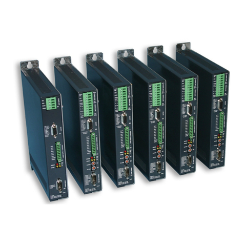
LinMot
LinMot E1100 Series User manual
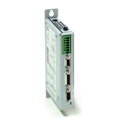
LinMot
LinMot B1100-PP User manual

LinMot
LinMot B1100-PP User manual
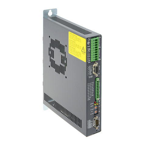
LinMot
LinMot E1100-GP User manual
LinMot
LinMot E1250-PL Series User manual
LinMot
LinMot E100 Series User manual

LinMot
LinMot Series E1400-GP User manual
