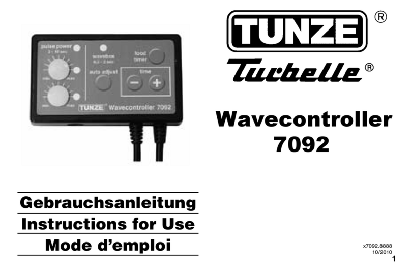
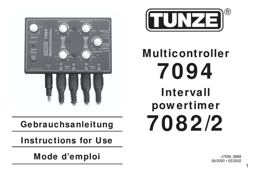
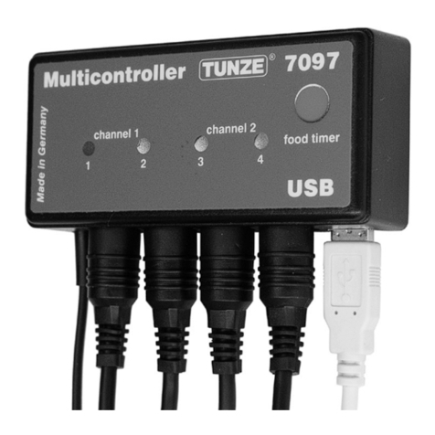
Tunze RO Water Controller 8555 User manual

2 3
Seite
4
6
8
10
12
14
16
18
20
22
22
24-25
26
28
Page
5
7
9
11
13
15
17
19
21
23
23
24-25
27
28
Page
5
7
9
11
13
15
17
19
21
23
23
24-25
27
28
Inhalt
Allgemeines
Entsorgung / Funktion
Sicherheitshinweise
Platzwahl Controller / Befestigung
Halterung an senkrechter Scheibe
Sensorhalterung mit Verlängerung
Halterung an waagerechter Scheibe
Halterung an Glasscheibe kleben
Controller 8555
Einstellen der Zeitüberwachung
Zubehör
Teileliste – Ersatzteile
Garantie
Entsorgung
Table of Contents
General aspects
Disposal / function
Safety instructions
Location for controller / attachment
Holding device on vertical aquarium pane
Sensor holding device with extension
Holding device on horizontal aquarium pane
Sticking the holding device on to the glass pane
Controller 8555
Adjustment of the time controller
Accessories
List of parts / spare parts
Guarantee
Disposal
Sommaire
Généralités
Gestion des déchets / Fonction
Sécurité d’utilisation
Placement du Controller / Fixation
Fixation sur vitre verticale
Fixation des capteurs avec prolongateur
Fixation sur vitre horizontale
Fixation par collage
Controller 8555
Réglage du temps de surveillance
Accessoires
Liste des pièces – Pièces détachées
Garantie
Gestion des déchets
TUNZE®Aquarientechnik GmbH
Seeshaupter Straße 68
82377 Penzberg - Germany
Tel: +49 8856 2022
Fax: +49 8856 2021
info@tunze.com
www.tunze.com
Aquatic Eco Engineering
TUNZE
®

4 5
Allgemeines
Der TUNZE®RO Water Controller 8555 ist eine
automatische Wasserstandsregelung für die TUNZE®
RO Station mit Reinwasserbehälter oder jeden
anderen Wasserbehälter mit Nachfüllautomatik für
Aquarien. Er besteht aus einem Controller (1), zwei
Sensoren (2), einem Wasserventil (3) und einem 12 V-
Netzteil (4). Je nach Bedarf kann das Wasserventil
durch die Schaltsteckdose 3150.110 (5) für Netzbetrieb
ausgetauscht werden.
Für die Nano RO Station 8515 wird dieses Nachfüllgerät
nicht empfohlen.
Wird die Position der Sensoren des RO Water
Controllers vertauscht, kann mit der Schaltsteckdose
3150.110 und einer Pumpe ein Wasserbehälter
zielgesteuert entleert werden, er kann damit zum
automatischen Füllen oder Leeren von Behältern
verwendet werden.
Mit zwei Gerätekombinationen lässt sich eine
Wasserwechselanlage bauen.
Dieses Gerät ist für Benutzer (einschl. Kinder) mit
eingeschränkten physischen, sensorischen oder
psychischen Fähigkeiten bzw. ohne jegliche Erfahrung
oder Vorwissen nur dann geeignet, wenn eine
angemessene Aufsicht oder ausführliche Anleitung
zur Benutzung des Geräts durch eine verantwortliche
Person sichergestellt ist (6).
General aspects
TUNZE®RO Water Controller 8555 is an automatic
water level regulator for the TUNZE®RO Station with
pure water tank or with any other water tank with an
automatic rell system for aquariums. It consists of a
controller (1), two sensors (2), a water valve (3), and
an 12 V power supply unit (4). Depending on the
demand, the water valve can be tted for submerged
operation by means of the switched socket outlet
3150.110 (5) for mains operation.
We do not recommend this rell unit for Nano RO
Station 8515.
If the position of the sensors of the RO Water
Controller is reversed, the switched socket outlet
3150.110 and a pump can be used to empty a water
tank, and thus it can also be used for automatic
lling or emptying of tanks.
By means of two combinations, a water changing
system can be built.
This device is suitable for users (including children)
with limited physical, sensorial or mental abilities or
without any experience or previous knowledge, if
suitable supervision or detailed instructions on the
operation of the device is provided by a responsible
person (6).
Généralités
TUNZE®RO Water Controller 8555 est une remise à
niveau automatique avec régulation pour osmoseur
inverse TUNZE®RO Station ou tous types
d’osmoseurs inverses avec réservoir d’eau pure. Il se
compose d’un contrôleur (1), de deux capteurs (2),
d’une électrovanne (3) et d’une alimentation secteur
12 V (4). Pour piloter un appareil alimenté sur
secteur, l’électrovanne peut être remplacée par la
prise commandée 3150.110 (5).
Cet appareil n’est pas conseillé pour Nano RO
Station 8515.
Il est encore possible d’eectuer la vidange
contrôlée d’un réservoir en inversant simplement
la position des capteurs RO Water Controller tout
en utilisant une prise commandée. En combinant
deux appareils, il est possible de construire une
installation de changement d’eau automatique.
Les utilisateurs (enfants inclus) ayant des limitations
physiques, sensorielles, psychiques, ne bénéciant
pas d’une expérience ou de connaissances
susantes ne peuvent utiliser cet appareil qu’avec
le concours d’une tierce personne responsable,
assurant la surveillance ou veillant à l’observation
du mode d’emploi (6).
6 7
Entsorgung:
(nach RL2002/96/EG)
Gerät und Batterie dürfen nicht dem normalen
Hausmüll beigefügt werden, sondern müssen
fachgerecht entsorgt werden.
Wichtig für Europa: Gerät über Ihre kommunale
Entsorgungsstelle entsorgen.
Funktion
TUNZE®RO Water Controller 8555 verwendet zwei
Sensoren(Schwimmschalter),d.h.einSensor(1)zum
Einschalten des Ventils und zum Überwachen des
Wasserniveaus (LED Water on) und ein Sensor (2)
zum Ausschalten (LED Water o). Der Controller
enthält auch eine elektronische Zeitüberwachung
die nach 12 Stunden (Auslieferungszustand) oder
24 Stunden. Dauerlauf das Ventil stoppt (Time out).
Dies kann einen Überlauf des Behälters vermeiden,
z.B. bei Blockierung eines Sensors. Nach Drücken
der Taste „Reset“ (3) ist dann der Water Controller
wieder arbeitsfähig.
Montage des Ventils, siehe Anleitung 8550 /
Zubehör.
Disposal
(in keeping with RL2002/96/EU)
The device and the battery may not be disposed of
in normal domestic waste; it has to be disposed of
in an expert manner.
Important for Europe: Devices can be disposed of
through your community’s disposal area.
Function
TUNZE®RO Water Controller 8555 uses two
sensors (oat switches) i.e. one sensor (1) to switch
on the valve and to monitor the water level (LED
Water On) and one sensor (2) for switching the
system o (LED Water O). The controller also
contains an electronic time monitor, which stops
the valve after twelve hours (delivery condition) or
twenty-four hours of continuous operation (time
out). This may prevent the container from owing
over when a sensor is blocked, for example. After
pressing the “Reset” (3) button, the water controller
is operational again.
Installation of the valve, see instructions 8550 /
accessories.
Gestion des déchets
(directive RL2002/96/EG)
Cet appareil et sa batterie ne doivent pas être jetés
dans les poubelles domestiques mais dans les
conteneurs spécialement prévus pour ce type de
produits.
Important pour l’Europe : l’appareil doit être recyclé
par votre centre de recyclage communal.
Fonction
TUNZE®RO Water Controller 8555 utilise deux
capteurs (capteurs magnétiques à otteurs), c’est-
à-dire un capteur (1) pour l’enclenchement de
l’électrovanne etlasurveillanceduniveaud’eau (LED
Water on) et un capteur (2) pour le déclenchement
(LED Water o). Le contrôleur comporte aussi une
surveillance de la durée d’enclenchement, arrêtant
l’électrovanne après un temps de fonctionnement
continu de 12 heures (réglage de série) ou 24
heures (Time out). Cette sécurité peut éviter un
débordement du réservoir d’eau pure, par exemple
suite au blocage d’un capteur. Après une action
sur le bouton « Reset » (3), Water Controller est à
nouveau opérationnel.
Pour le montage de l’électrovanne, voir notice 8550
/ Accessoires.

8 9
Sicherheitshinweise
Netzteil 5012.01 und Controller 8555 nur an
trockener und gut belüfteter Stelle anbringen! (1)
Nicht in die Nähe von Heiz- und Wärmequellen
aufstellen (2), Umgebungstemperatur max. + 35°C.
Kabel nicht knicken (3).
Magnetscheibenreiniger oder andere Magnete
nicht in die Nähe des Sensors bringen, sonst
Funktionsstörung möglich, mind. 20 cm Abstand
halten (4).
Vor Inbetriebnahme prüfen, ob Betriebsspannung
mit Netzspannung übereinstimmt.
Kabel nicht reparieren, sondern Geräte zur
Reparatur geben.
Nur an empfohlene TUNZE-Geräte anschließen.
Beim Betrieb kann das Ventil heiß werden (ca 60°C).
Schwimmschalter, interne elektrische
Komponenten und Ventil kann fest werden und
an angeschlossenen Umkehrosmosegeräten
Wasserschäden verursachen. RO Water Controller
daher nicht unbeaufsichtigt betreiben.
Bitte beachten Sie auch die Sicherheitshinweise bei
den RO-Geräten !
Gebrauchsanleitung gut aufbewahren.
Safety instructions
Mount power supply unit 5012.01 and controller 8555
in dry and well ventilated locations only ! (1)
Do not mount in the vicinity of heat sources (2); ambient
temperature max. 35° Celsius (95° F).
Do not kink the cable (3).
Do not situate magnetic pane cleaners or other
magnets in the vicinity of the sensor, as otherwise
functional failure is possible; keep a distance of at least
20 cm (7.8 in.).
Prior to initial operation, please check whether the
operating voltage corresponds to the mains voltage
available.
Do not repair a damaged mains cable, but have the
units repaired.
Connect to recommended TUNZE units only.
During the operation, the valve may turn hot (approx.
60° Celsius / 140° F).
Float switches, internal electric components and valves
can cease up, and may cause water damage to the
reverse osmosis units connected. For this reason, do
not operate the RO Water Controller unattended.
Please also observe the safety instructions for the RO
units !
Keep the operating instructions in a safe place.
Sécurité d’utilisation
Positionnez l’alimentation 5012.01 et le Controller
8555 en un endroit sec et bien aéré ! (1)
Ne positionnez pas les appareillages près d’une
source de chaleur (2), température max. +35°C.
Ne pliez pas les câbles (3).
An d’évitez tous défauts, n’approchez pas de
sources magnétiques à moins de 20 cm des
capteurs (4).
Avant toute mise en fonction, vériez la compatibilité
de l’alimentation avec le réseau électrique.
N’essayez pas de réparer un câble mais renvoyez
l’appareil au Service Réparations.
Ne raccordez RO Controller qu’aux appareillages
TUNZE® conseillés.
Lors de son fonctionnement, l’électrovanne peut
être très chaude (env. 60°C).
Les capteurs, les composants électriques internes
et l’électrovanne peuvent se bloquer et provoquer
un débordement par fonctionnement permanent de
l’osmoseur inverse. Pour cela, ne pas utiliser RO
Water Controller sans surveillance.
Veuillez observer les sécurités d’utilisation des
appareils RO !
Veuillez attentivement consulter le mode d’emploi.

10 11
Platzwahl für Controller 8555
Wand muss trocken sein, Platz nicht über dem
Aquarium wählen! (1)
Vorhandene Kabellänge beachten, Verlängerung
nicht möglich!
Kontrollleuchten müssen sichtbar sein!
Kabelanschlüsse so verlegen, dass kein Wasser
entlang laufen kann und in den Controller
gelangt! (2).
Befestigung
Zur Befestigung des Controllers sind die
beiliegenden selbstklebenden Kunststo-
Hakenbänder vorgesehen (3).
Untergrund muss fettfrei, sauber und glatt sein, z.B.
Kunststoäche.
Bänder auf Gehäuse kleben, dazu Schutzfolie
abziehen und anpressen.
Danach die zweite Schutzfolie abziehen und Gerät
an gewünschter Stelle positionieren und andrücken,
dabei auf die Lage der Kabel achten.
Selecting the position for Controller 8555
The wall has to be dry; do not select a position
above the aquarium ! (1)
Observe available cable length; an extension is not
possible !
The indicator lamps have to be visible !
Place the cable connections in such a way that no
water can run along and get into the controller (2) !
Attachment
For attachment of the controller, please use
the plastic self-adhesive hook and loop strips
enclosed (3).
The surface has to be free from grease, clean and
smooth, such as a plastic surface.
Stick the strips to the housing; for this purpose
remove the protective lm and press down.
Subsequently remove the second protective lm,
place the unit at the requested position and press
down, observing the position of the cable in the
process.
Placement du Controller 8555
La surface doit être sèche, n’utilisez pas un
emplacement au-dessus de l’aquarium ! (1)
Observez la longueur des câbles, leur prolongation
est impossible !
Les voyants lumineux doivent rester visibles !
Positionnez les câbles de telle manière à ce
que la pénétration de l’eau dans le boîtier soit
impossible ! (2).
Fixation
Pour sa xation, le Controller est livré avec des
bandes Velcro autocollantes (3).
La surface de collage doit être propre, sèche
et plane, par exemple une surface en matière
plastique.
Collez les bandes Velcro sur le boîtier, pour cela
retirez les protections puis pressez.
Déposez les deux protections restantes, positionnez
l’appareil à l’endroit voulu en observant la longueur
du câble et pressez sur la surface de xation.

12 13
Halterung der Sensoren an senkrechter
Aquarienscheibe oder Behälter
(1) Halter vormontieren.
(2) Einstellen der Glasstärke (max.19mm) mit der
unteren Halteschraube.
(3) Klemmschraube anziehen. Auf festen Sitz
achten.
(4) Schiebeteil mit Halteplatte für Sensor
an gewünschte Stelle positionieren. Bei
der Halteplatte (5) muss der Stift in Richtung
Schwimmer zeigen.
Sensor mit Kabel nach oben in Sensorhalter
einführen, danach Sensorschrauben anziehen.
Zubehör
(6) Für Glasscheiben bis 39mm Dicke gibt es
längere Schrauben: 2 Schrauben M5 x 60 mm, Art.
Nr. 3000.244.
Holding device of the sensors on a
vertical aquarium pane or on a tank
(1) Premount the holding device.
(2) Use the lower retaining screw to set the glass
thickness (max. 19 mm (.74 in.)).
(3) Tighten the clamping screw. Ensure a tight t.
(4) Position the sliding part at the requested position
by means of the holding plate of the sensor. The pin
on holding plate (5) has to point in direction of the
oat switch.
Insert the sensor with cable upwards into the sensor
holding device; subsequently tighten the sensor
screws.
Accessories
(6) Longer screws are available for glass panes up
to a thickness of 39 mm (1.33 in.): 2 screws M5 x 60
mm (2.36 in.), article No. 3000.244.
Fixation des capteurs sur vitre
verticale ou conteneur
(1) Procédez à un premier assemblage du support.
(2) Ajustez le support à l’épaisseur du verre (max.
19mm) à l’aide de la vis de réglage inférieure.
(3) Serrez la vis de réglage supérieure, veillez à une
bonne assise.
(4) Positionnez la pièce coulissante du support de
capteur à la position souhaitée. Sur la plaque de
xation (5), l’ergot doit être côté capteur.
Insérez le capteur dans le support, câble vers le
haut, puis resserrez l’écrou du capteur.
Accessoire
(6) Pour des épaisseurs de vitre jusqu’à 39mm,
utilisez les deux vis inox M5x60mm, référence
3000.244.

14 15
Sensorhalterung mit Verlängerung an
senkrechter Aquarienscheibe oder
Behälter befestigen
(7) Verlängerung mit Halteschiene verbinden,
dazu Gewindeplatte 3000.27 an der Rückseite der
Schienen einsetzen und mit je einer Schraube von
vorn befestigen.
(8) Weitere Montageschritte siehe wie beschrieben
bei „Halterung an senkrechter Aquarienscheibe
oder Behälter“ (1-5).
Water o
Water on
Attaching the sensor holding device with
extension to a vertical tank pane or tank
(7) Use the retaining rail to link the extension; for
this purpose place the threaded plate 3000.27 on
the rear side of the rails and screw down from the
front with one screw each.
(8) For other mounting steps, please refer to the
description in „Attachment to vertical aquarium pane
or container“ (1 - 5).
Fixation des capteurs avec prolongateur
sur vitre verticale ou conteneur
(7) Raccordez la prolongation et la barre de montage
initiale. Pour cela, placez la plaquette 3000.27 à
l’arrière des barres et solidarisez le tout à l’aide des
deux vis insérées par l’avant.
(8) Autres étapes de montage, voir Fixation des
capteurs sur vitre verticale ou conteneur (1 - 5).

16 17
Halterung der Sensoren an waagerechter
Aquarienscheibe oder Behälter
(1) Klemmhalter vormontieren.
(2) Einstellen der Glasstärke (max.19mm) mit der
Halteschraube.
(3) Klemmschrauben anziehen.
(4) Halteschiene mit Schiebeteil für Sensor (5)
vormontieren, dabei gewünschte Position des
Sensors einstellen.
(6) Schraube und Mutter an Halteschiene lose
befestigen und in Klemmhalter (1) einhängen und
festschrauben.
Sensor mit Kabel nach oben in Sensorhalter
einführen, danach Sensorschrauben anziehen.
Zubehör
(7) Für Glasscheiben bis 39mm Dicke gibt es
längere Schrauben: 2 Schrauben M5 x 60mm, Art.
Nr. 3000.244
Holding device of the sensors on a
horizontal aquarium pane or on a tank
(1) Premount the holding clamp.
(2) Use the retaining screw to set the glass thickness
(max. 19 mm (.74)).
(3) Tighten the clamping screws.
(4) Premount the retaining rail with the sliding part
for the sensor (5), and set the requested position of
the sensor in the process.
(6) Loosely t the screw and nut on the retaining rail,
suspend in holding clamp (1), and screw down.
Insert the sensor with cable upwards into the sensor
holding device; subsequently tighten the sensor
screws.
Accessories
(7) Longer screws are available for glass panes up
to a thickness of 39 mm (1.53 in.): 2 screws M5 x 60
mm (2.36 in.), article No. 3000.244.
Fixation des capteurs sur vitre
horizontale ou conteneur
(1) Procédez à un premier assemblage du support.
(2) Ajustez l’ensemble de serrage du support à
l’épaisseur du verre (maxi 19 mm) par la vis de
réglage.
(3) Serrez la vis de serrage.
(4) Assemblez la barre de montage et la pièce
coulissante pour le capteur (5), choisissez la bonne
position du capteur.
(6) Insérez la vis dans la barre de montage et xez
le tout au support (1) à l’aide de l’écrou.
Insérez le capteur dans le support, câble vers le
haut, puis resserrez l’écrou du capteur.
Accessoires
(7) Pour des épaisseurs de vitre jusqu’à 39mm,
utilisez les deux vis inox M5x60mm, référence
3000.244.

18 19
Halterung an Glasscheibe kleben
Bei dieser Befestigung entfällt der übliche
Klemmhalter. Dafür müssen zwei Halteplättchen
pro Halteschiene mit Silikonkleber Art. Nr. 104.72
an die Aquarienscheibe geklebt werden. Wir
empfehlen die Verklebung an der Luft, da die
Haltbarkeit unter Wasser geringer ist und nur
gelingt, wenn folgendes genau beachtet wird:
Schiebeteile (2) und Schiene (1) des Halters
zusammenschieben und Gewindeplatte (3) an
den äußersten Enden der Schiene mit je einer
beiliegenden Schraube (4) festschrauben, glatte
Plättchenäche muss an Schiene liegen.
Bei trockener Verklebung, Klebestelle mit
Reinigungsbenzin (fettfrei) säubern.
Bei Unterwasserverklebung, die Klebestelle im
Aquarium mit Klingenreiniger von Algen und
Schmierlm befreien.
Gereinigte Gewindeplatten (3) gleichmäßig mit 2-3
mm Silikon (5) einstreichen und fest an Scheibe
drücken, dabei soll Silikon in das leere Gewindeloch
eindringen.
Silikon unter Wasser innerhalb von 20 Sekunden
wegen Hautbildung verarbeiten.
Klebung muss 24 Stunden unbelastet aushärten.
Sticking the holding device
on to the glass pane
The standard holding clamp is not required for this
type of attachment. Instead, two retaining plates for
each perforated rail have to be adhered to the tank
pane with silicone adhesive, article No. 104.72. We
recommend to carry out the attachment work in fresh
air as the holding capacity is lower in water and is
successful only, if the following points are observed:
Push the sliding parts (2) and the rail (1) of the holding
device together, and screw down the threaded
plate (3) at the extreme ends of the rail with one
of the enclosed screws (4) each; the smooth plate
surface has to make contact to the rail.
For dry sticking, use cleansing alcohol (free of
petroleum or oils) to clean the sticker point.
For under-water attachment, use the blade cleaner to
remove algae and any slimy lm from the attachment
point in the tank.
Apply 2 to 3 mm (.07 to .11 in.) of silicone (5) to the
cleaned threaded plates (3), and press them down
on to the pane tightly so that the silicone penetrates
the empty threaded hole.
Under water, process the silicone within 20 seconds
to avoid skin formation.
The bond has to cure for 24 hours without load.
Fixation par collage
Cette xation n’utilise pas le support universel.
Chaque barre de montage nécessite deux plaquettes
à coller sur la vitre à l’aide de colle silicone référence
104.72. Nous recommandons le collage à l’air car
un collage sous eau n’est able qu’en observant
scrupuleusement la procédure suivante :
Assemblez la barre de montage (1) et la pièce
coulissante (2), montez les deux plaques de
collage (3) aux extrémités de la barre à l’aide des
vis (4), parties plates des plaques de collage côté
barre.
Pour un collage à l’air, nettoyez les parties à coller à
l’aide d’un dégraissant.
Pour un collage sous eau, débarrassez les vitres de
toutes algues ou lm bactérien à l’aide d’une raclette
à lame.
Recouvrez les plaques de collage dégraissées (3)
d’une épaisseur de 2 à 3 mm de colle silicone (5) et
appliquez le tout contre la vitre. La colle doit pénétrer
dans les orices letés des plaques.
Sous eau, le temps de a mise en place ne doit pas
dépasser 20 sec. en raison de la formation d’une
peau de surface sur la colle.
Le collage doit avoir polymérisé durant 24 heures
avant toute sollicitation mécanique.

20 21
Leuchtdioden (LED) am Controller 8555
Grüne LED (1) “DC Power” leuchtet = Controller mit
Strom versorgt.
Gelbe LED (2) “Water on” leuchtet = Wasserstand
niedrig, Ventil in Betrieb.
Gelbe LED (3) “Water o” leuchtet = Wasserstand
hoch, Ventil außer Betrieb.
Rote LED (4) „Time out” leuchtet = elektronische
Zeitüberwachung, die nach 12 Stunden
(Auslieferungszustand) oder 24 St. Dauerlauf
das Ventil stoppt (Time out). Nach Drücken der
Taste „Reset“ wird dann der Controller wieder
arbeitsfähig.
Light-emitting diodes (LEDs)
on Controller 8555
Green LED (1) “DC Power” is lit = controller is
energized.
Yellow LED (2) “Water On” is lit = water level low;
valve in operation.
Yellow LED (3) “Water O” is lit = water level high;
valve not operating.
Red LED (4) „Time Out“ is lit = an electronic
time monitor, which stops the valve after twelve
hours (default condition) or twenty-four hours of
continuous operation (time out). After pressing the
“Reset” button, the controller is operational again.
Controller 8555 et diodes LED
LED verte (1) “DC Power” allumée = Controller sous
tension.
LED jaune (2) “Water on” allumée = niveau d’eau
bas, électrovanne en service.
LED jaune (3) “Water o” allumée = niveau d’eau
haut, électrovanne hors service.
LED rouge (4) “Time out” allumée = arrêt de
l’électrovanne par surveillance de la durée
d’enclenchement, temps de fonctionnement continu
de 12 heures (réglage de série) ou 24 heures
dépassé (Time out). Après une action sur le bouton
« Reset », le Controller est à nouveau opérationnel.

22 23
Einstellen der Zeitüberwachung (Time out)
Im Controller 8555 kann die Zeitüberwachung je nach
Anlage und Bedarf auf 12 (Auslieferungszustand)
oder 24 St. eingestellt werden. Sie kann eine
Überfüllung des Behälters vermeiden, z.B. bei
Blockierung eines Sensors.
Netzstecker ziehen!
Deckel entnehmen, dazu beide Schrauben auf
Gehäuserückseite lösen (1).
Jumper (roter Stift) auf Platine verstellen (2).
Achtung Leuchtdioden (LED) und Kabel nicht
beschädigen!
Zubehör
Schaltsteckdose 3150.110
Bei dem Water Controller 8555 kann das beiliegende
Ventil durch die Schaltsteckdose 3150.110 für
Netzbetrieb ersetzt werden (3). Dazu wird das
Kabel der Schaltsteckdose am Platz des Ventils an
die Lüsterklemme des Controllers angeschlossen
(Niedervolt Spannung) und die Schaltsteckdose am
Netzstecker eingesteckt. Die Schaltsteckdose kann
zum Schalten von Kreiselpumpen, Dosierpumpen,
etc. mit 230V max.1800W (115 V / 900W) verwendet
werden.
Setting the time monitor (time out)
Depending on the plant and the requirement, the
time monitor in the controller 8555 can be set to
twelve hours (default condition) or twenty-four
hours. This may prevent the container from owing
over when a sensor is blocked, for example.
Remove the mains plug !
Remove the cover; for this purpose undo the screws
on the rear side of the housing (1).
Adjust jumper (red pin) on the PCB (2).
Caution ! Do not damage the light-emitting diodes
(LEDs) or the cables in the process !
Accessories
Switched socket outlet 3150.110
In case of TUNZE®RO Water Controller 8555,
the enclosed valve can be replaced by switched
socket outlet 3150.110 for mains operation (3).
For this purpose, the cable of the switched socket
outlet is connected to the luster terminal of the
controller instead of the valve (low voltage) and the
switched socket outlet is plugged to the mains plug.
The switched socket outlet can be used to switch
centrifugal pumps, metering pumps, et cetera with
130 V, max. 1,800 W (115 V / 900 W).
Réglage du temps de
surveillance ( Time out )
En fonction de l’installation et de l’utilisation, le temps
de surveillance du Controller 8555 peut être de 12
heures (réglage de série) ou de 24 heures (Time out).
Cette fonction évite le débordement du réservoir, par
exemple en cas de blocage d’un capteur.
Déconnectez l’alimentation électrique !
Ouvrez le couvercle. Pour cela, déposez les deux vis
de fermeture à l’arrière de l’appareil (1).
Veillez à ne pas abîmer les diodes LED.
Déplacer le Jumper rouge sur la platine (2).
Remontez l’ensemble en veillant à ne pas
endommager les diodes LED et les câbles.
Accessoire
Prise commandée 3150.110
L’électrovanne livrée de série avec Water Controller
8555 peut être remplacée par la prise commandée
3150.110 (3) an d’utiliser des appareillages
fonctionnant sur le secteur. Il sut pour cela de
raccorder le câble de la prise commandée au
Controller, en lieu et place de celui de l’électrovanne
(basse-tension) puis de brancher la prise
commandée sur le secteur. Elle permet alors le
pilotage d’une pompe centrifuge, d’une pompe de
dosage, etc. avec 230V max.1.800W (115V / 900W).

24 25
Teileabbildung • Illustrations of parts • Illustration des pièces
8555.000 Teileliste
RO Water Controller
List of parts
RO Water Controller
Liste des pièces
RO Water Controller
18555.100 Controller 8555 Controller 8555 Controller 8555
28555.200 Valve Water valve Electrovanne
35012.010 Netzteil 12V Power supply unit 12V Alimentation secteur 12V
43000.220 Lochschiene Mounting bar Barre de montage
53155.100 Schiebeteil
Sicherheitssensor Sliding unit for sensor Piéce coulissante
pour capteur
63150.310 Halteplatte für Sensoren Holder board Plaque pour capteur
73000.270 Klebebefestigung für Halter Adhesive attachment
for holder
Plaquettes de
support à coller
83000.240 Klemmhalter Clamp holder Attache de support
8a 3000.243 Schraubenset Screw set Set de vis
Die Teileabbildung zeigt die mitgelieferten Einzelteile. Die Ersatzteilliste enthält auch Teile die von den
Teileabbildungen abweichen können.
The illustration shows the individual parts supplied. The list of spare parts may also contain parts which
deviate from the illustrations.
L’illustration des pièces indique les diérentes pièces utilisées. La liste de pièces détachées comporte
aussi des pièces pouvant diérer de cette illustration.

26 27
Garantie
Für das von TUNZE®Aquarientechnik GmbH
hergestellte Gerät wird für einen Zeitraum von
vierundzwanzig (24) Monaten ab dem Kaufdatum eine
begrenzte Garantie gewährt, die sich auf Material-
und Fabrikationsmängel erstreckt. Im Rahmen der
entsprechenden Gesetze beschränken sich Ihre
Rechtsmittel bei Verletzung der Gewährleistungspicht
auf die Rückgabe des von TUNZE®Aquarientechnik
GmbH hergestellten Gerätes zur Reparatur oder zum
Ersatz, was im Ermessen des Herstellers liegt. Im
Rahmen der entsprechenden Gesetze sind dies die
einzigen Rechtsmittel. Folgeschäden und sonstige
Schäden sind ausdrücklich davon ausgeschlossen.
Defekte Geräte müssen in der Originalverpackung
zusammenmitdemKassenzettelineinerfreigemachten
Sendung an den Händler oder den Hersteller gesandt
werden. Unfreie Sendungen werden vom Hersteller
nicht angenommen.
Garantieausschluss besteht auch für Schäden durch
unsachgemäße Behandlung (z.B. Wasserschäden),
technische Änderungen durch den Käufer, oder durch
Anschluss an nicht empfohlene Geräte.
Technische Änderungen, insbesondere solche, die der
Sicherheit und dem technischen Fortschritt dienen,
behält sich der Hersteller vor.
Guarantee
The unit manufactured by TUNZE®Aquarientechnik
GmbH carries a limited guarantee for a period of
twenty-four (24) months after the date of purchase
covering all defects in material and workmanship.
Within the framework of the corresponding
laws, your remedies in case of a violation of the
guarantee obligation shall be limited to returning
the unit manufactured by TUNZE®Aquarientechnik
GmbH for repair or replacement at the discretion
of the manufacturer. Within the framework of the
corresponding laws, the said shall be the only
remedies. Consequential damage and/or other
damage shall be excluded therefrom explicitly.
Defect units shall have to be shipped to the dealer or
the manufacturer in the original packaging together
with the sales slip in a pre-paid consignment.
Unpaid consignments will not be accepted by the
manufacturer.
Exclusion from guarantee shall exist also in case
of damage caused by inexpert handling (such as
water damage), technical modication carried out
by the buyer or by connection to devices which
have not been recommended.
Subject to technical modications, especially those
which further safety and technical progress.
Customers in USA, please refer to seperate Limited
Warranty for United States brochure.
Garantie
Cet appareil manufacturé par TUNZE®Aquarientechnik
GmbH bénécie d’une garantie limitée à une durée
légale de vingt quatre mois (24) à partir de la date d’achat
et concernant les vices de fabrication et de matériaux.
Dans le cadre des lois correspondantes, les voies de
recours lors d’un dommage se limitent au retour de
l’appareil produit par TUNZE®Aquarientechnik GmbH
à son service réparation ou au remplacement de
l’appareil ce qui reste de l’appréciation du fabriquant.
Dans le cadre des lois correspondantes, il s’agit de
l’unique voie de recours. D’autres dommages et
dégâts en sont catégoriquement exclus. Les appareils
défectueux doivent être expédiés dans leur emballage
d’origine, accompagnés du bordereau de caisse dans
un envoi aranchi à l’adresse du commerçant ou
du fabricant. Les envois non aranchis ne sont pas
acceptés par le fabricant.
L’exclusion de garantie concerne aussi les dégâts par
traitement incorrect (par exemple des dégâts causés
par l’eau), les modications techniques eectuées par
l’acheteur ou le raccordement à des appareillages non
recommandés par le fabricant.
Le fabricant se réserve le droit d’eectuer des
modications techniques, en particulier dans le
domaine de la sécurité et du progrès technique.
TUNZE®Aquarientechnik GmbH
Seeshaupter Straße 68
82377 Penzberg - Germany
Tel: +49 8856 2022
Fax: +49 8856 2021
info@tunze.com
www.tunze.com
Aquatic Eco Engineering
TUNZE
®

28
Entsorgung:
(nach RL2002/96/EG)
Gerät und Batterie darf nicht dem normalen Hausmüll
beigefügt werden, sondern muss fachgerecht entsorgt
werden.
Wichtig für Europa: Gerät und Batterie über Ihre
kommunale Entsorgungsstelle entsorgen.
Disposal
(in keeping with RL2002/96/EU)
Devices and batteries may not be disposed of in normal
domestic waste; it has to be removed in an expert
manner.
Important for Europe: Devices and batteries can be
disposed of through your community’s disposal area.
Gestion des déchets :
(directive RL2002/96/EG)
Cet appareil et batteries ne doit pas être jeté dans
les poubelles domestiques mais dans les conteneurs
spécialement prévus pour ce type de produits.
Important pour l’Europe : appareil et batteries
doivent être recyclés par votre centre de recyclage
communal.
Other Tunze Controllers manuals

Tunze
Tunze Multicontroller 7093 User manual

Tunze
Tunze 7097 User manual

Tunze
Tunze 7095 User manual

Tunze
Tunze SmartController 7000.001 User manual

Tunze
Tunze 7074/2 User manual

Tunze
Tunze SmartController 7000 User manual

Tunze
Tunze 7094 User manual

Tunze
Tunze 7096 User manual

Tunze
Tunze Osmolator 3 User manual

Tunze
Tunze Turbelle Wavecontroller 7092 User manual