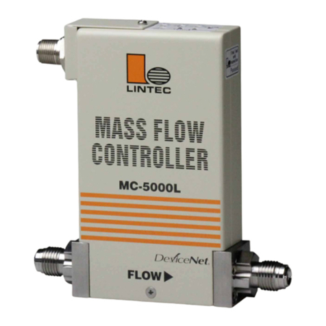
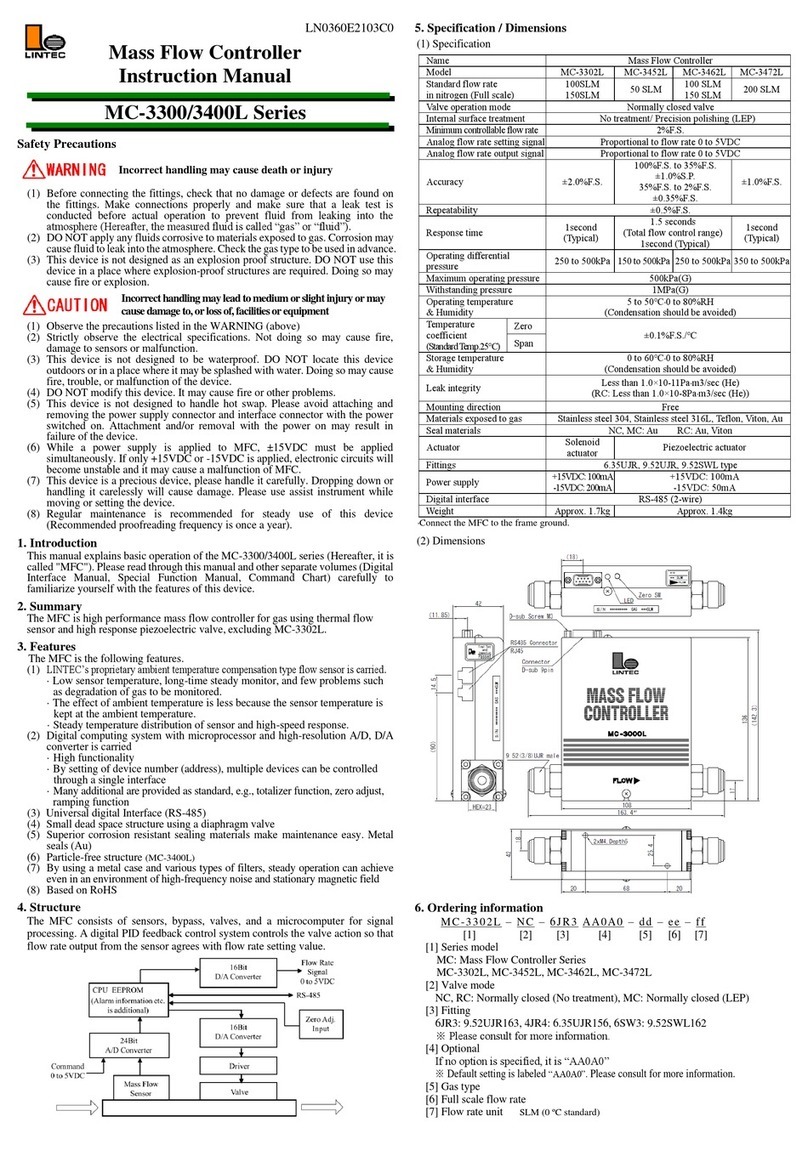
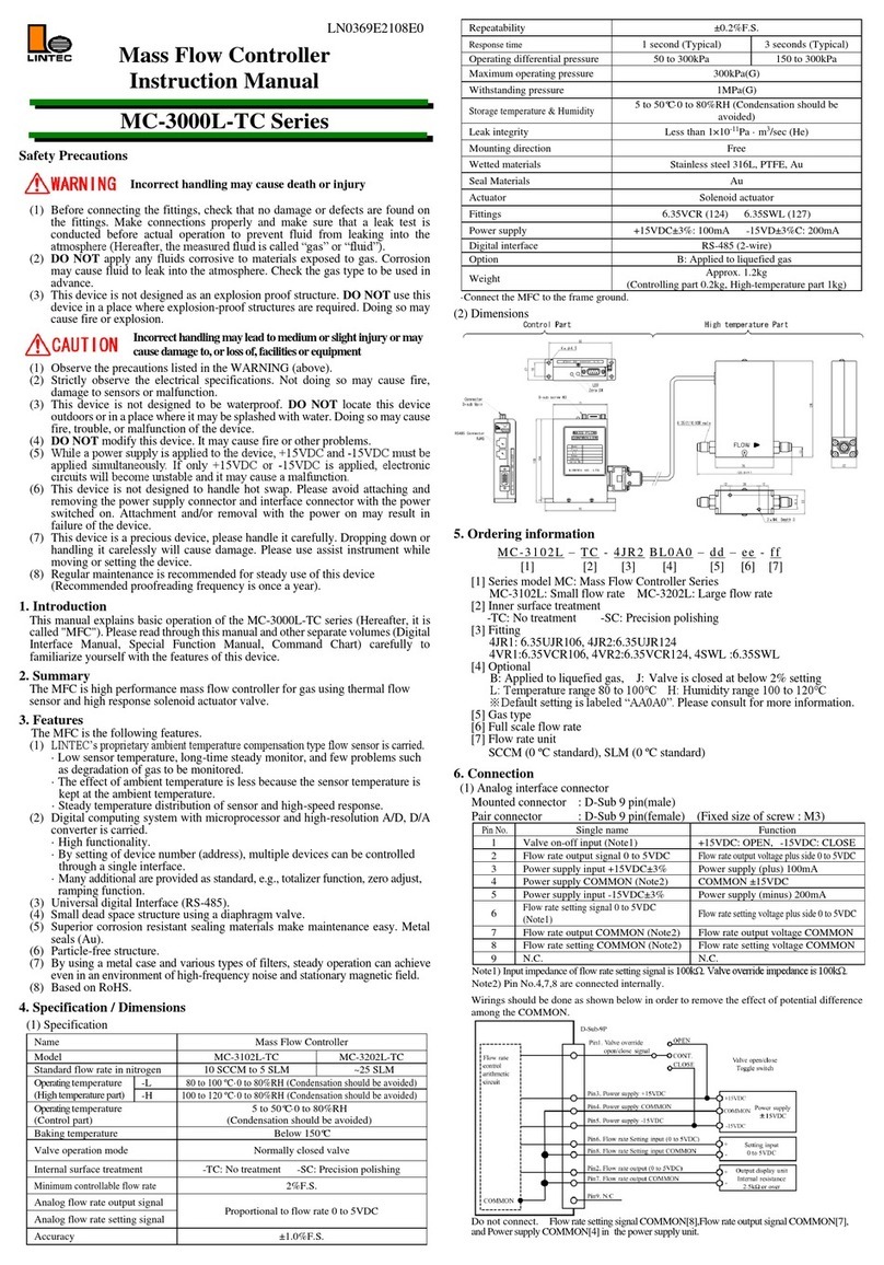
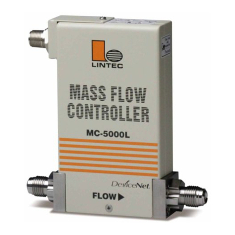
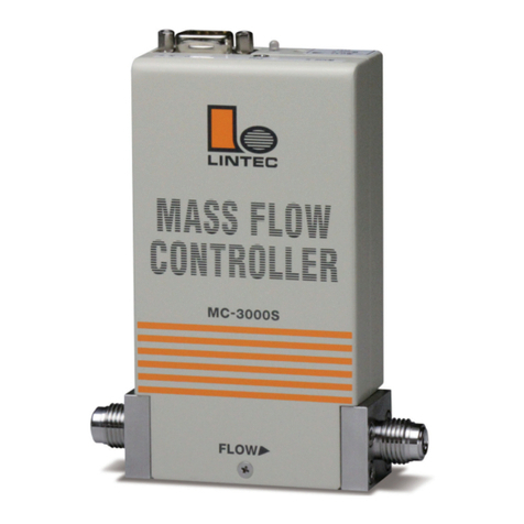
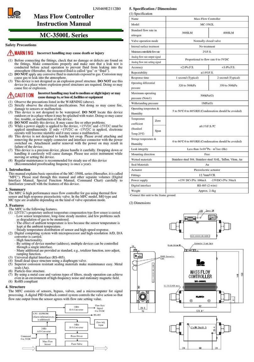
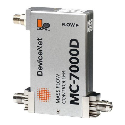
Lintec MC-700 Series User manual

LN0427E2103E0
Mass Flow Controller
Instruction Manual
MC-700 Series
Safety Precautions
Incorrect handling may cause death or injury
(1) Before connecting the fittings, check that no damage or defects are found on
the fittings. Make connections properly and make sure that a leak test is
conducted before actual operation to prevent fluid from leaking into the
atmosphere (Hereafter, the measured fluid is called “gas” or “fluid”).
(2) DO NOT apply any fluids corrosive to materials exposed to gas. Corrosion may
cause fluid to leak into the atmosphere. Check the gas type to be used in advance.
(3) This device is not designed as an explosion proof structure. DO NOT use this
device in a place where explosion-proof structures are required. Doing so may
cause fire or explosion.
Incorrecthandlingmayleadtomedium orslightinjuryor may
causedamage to,orlossof,facilitiesorequipment
(1) Observe the precautions listed in the WARNING (above)
(2) Strictly observe the electrical specifications. Not doing so may cause fire,
damage to sensors or malfunction.
(3) This device is not designed to be waterproof. DO NOT locate this device
outdoors orin a place where it may be splashedwith water. Doing so may cause
fire, trouble, or malfunction of the device.
(4) DO NOT modify this device. It may cause fire or other problems.
(5) This device is not designed to handle hot swap. Please avoid attaching and
removing the power supply connector and interface connector with the power
switched on. Attachment and/or removal with the power on may result in failure
of the device.
(6) While a power supply is applied to MFC, ±15VDC must be applied
simultaneously. If only +15VDC or -15VDC is applied, electronic circuits will
become unstable and it may cause a malfunction of MFC.
(7) This device is a precious device, please handle it carefully. Dropping down or
handling it carelessly will cause damage. Please use assist instrument while
moving or setting the device.
(8) Regular maintenance is recommended for steady use of this device
(Recommended proofreading frequency is once a year).
1. Introduction
This manual explains basic operation of the MC-700 series (Hereafter, it is called
"MFC"). Please read through this manual and other separate volumes (Digital
Interface Manual, Special Function Manual, Command Chart) carefully to
familiarize yourself with the features of this device.
2. Summary
This device is the mass flow controller with the function of switching different
kinds of gas and flow rate (Hereafter called "variable function" or "VR"). By using
the 3 rotary switches on the MFC, the gas type and flow rate can be changed. The
rotary switches are placed conveniently on top of the MFC unit so that
adjustments can be made accordingly even after the unit is set in position. For old
models, stocking MFC for each of gas and flowrate was necessary because only
one spec is available to one MFC, and MC-700 can reduce your stocking because
it can be used for more than one spec with one MFC.
3. Features
The MFC has the following features.
(1) LINTEC’s proprietary ambient temperature compensation type flow sensor.
·The influence of ambient temperature is small due to the sensor temperature
control following the ambient temperature.
·Since the temperature distribution of the sensor is constant, high-speed response
is possible.
(2) Gas type and flow rate setting can be changed by using the 3 switches on the
mass flow controller unit.
(3) Digital interface (RS-485) is standard equipment and the maximum of 32 MFCs
could be connected together with daisy chain.
(Option: Digital interface RS-232C is possible)
(4) Small structure of dead volume using diaphragm valve.
(5) Stainless steel 316L is used because of good corrosion resistance and seal ability.
(6) Particule-free structure
(7) RoHS compliant, CE conformity
4. Structure
The MFC consists of sensors, bypass, valves, and a microcomputer for signal
processing. A digital PID feedback control system controls the valve action so that
flow rate output from the sensor agrees with flow rate setting value.
5. Specification / Dimensions
(1) Specification
Name
Mass Flow Controller
Model
MC-710
MC-720
MC-730
Standard flow rate in
nitrogen VR number
10SCCM to 3SLM
(VRnumber02to06)
3.1 to 10SLM
(VR number 07)
11 to 50SLM
(VRnumber08and09)
Valve operation mode
Normally closed / Normally open
Internal surface treatment
No treatment / Precision polishing
Flow rate control range
2% of full scale
Analog flow rate setting
signal
Proportional to flow rate: 0 to 5VDC
Analog flow rate output
signal
Proportional to flow rate: 0 to 5VDC
Variable function (VR)
Changeable by using rotary switches (0.50 to 2.00)
Range is limited by original flow rate range of unit
Accuracy (Note1)
±1.0%F.S.
Repeatability (Note1)
±0.2%F.S.
Response time
1sec (Typical)
Operating differential
pressure (Note2)
50 to 300kPa
100 to 300kPa
150 to 300kPa
Maximum operating
pressure
300kPa(G)
Withstanding pressure
1MPa(G)
Operational temp/
Humidity range
5 to 50°C / 0 to 80%RH (with no condensation)
(Accuracy insurance 15 to 35°C)
Storage temp /
Humidity range
0 to 60°C/ 0 to 80%RH (with no condensation)
Leak integrity
Less than 1×10-11Pa·m3/sec (He)
Mounting direction
Free
Materials exposed to gas
Stainless steel 316L, PCTFE, PTFE
Seal materials
Stainless steel 316L
Actuator
Piezo electric actuator
Fitting
6.35VCR Type: 124mm
6.35VCR Type: 106mm (option)
6.35SWL Type: 127mm (option)
Power supply
+15VDC±3%: 120mA -15VDC±3%: 50mA
Analog interface
D-sub 9pin (male), Fixed size of screw:M3
Digital interface
RS-485 (RJ45 Jack) 2-wire Maximum connection 32 units
RS-232C(RJ45Jack)Maximumconnection100units(R0/R1Option)
Weight
Approx. 1 kg
Note 1) The value at the time of shipping. This may change with usage of VR function.
Note 2) The value at the time of shipping. This may change with gas type and flow rate setting.
·Connect the MFC to the ground.
(2) Dimensions
6. Ordering information
MC-710 MC - 4VR2 A0A0A0 - 06 - N2 - 1.5SLM
[1] [2] [3] [4] [5] [6] [7]
[1] Model: MC: Mass Flow Controller Series MC-710 MC-720 MC-730
[2] Valve operation mode · Internal surface treatment
NO: Normally opened valve / No treatment
NC: Normally closed valve / No treatment
MO: Normally opened valve / Precision polishing
MC: Normally closed valve / Precision polishing
[3] Fitting
4VR2: 6.35VCRType 124mm
4VR1: 6.35VCRType 106mm (option)
4SWL: 6.35SWLType 127mm (option)
※Please consult us for other fitting types.
[4] Other options
Default settings is labeled “A0A0A0”, please consult for more information.
[5] VR Number
[6] Gas type
[7] Full scale flow rate and unit: SCCM(0°C standard), SLM(0°C standard)

7. Connection
(1) Analog interface connector
Mounted connector : D-Sub 9 pin(male)
Pair connector : D-Sub 9 pin(female) (Fixed size of screw : M3)
Pin
No.
Signal name
Function
1
Valve override open/close signal(Note3)
+15VDC:OPEN, -15VDC:CLOSE
2
Flow rate output signal 0 to 5VDC
Flowrateoutputvoltageplusside0to5VDC
3
Power supply input +15VDC±3%
Power supply (plus) 120mA
4
Power supply COMMON (Note4)
COMMON ±15VDC±3%
5
Power supply input -15VDC±3%
Power supply (minus) 50mA
6
Flowratesettingsignal 0to5VDC
Flow ratesettingvoltage0 to 5VDC (plus)
7
Flow rate output COMMON (Note4)
Flow rate output signal COMMON
8
Flow rate settingCOMMON (Note4)
Flow rate setting signal COMMON
Note3) Impedance for flow rate setting signal is 10MΩ, valve override signal resistance is 100kΩ.
Note4)Pin No.[4],[7]and No.[8] are connected internally in MFC.
Wirings should be done as shown below in order to remove the effect of potential difference
among the COMMON.
Do not connect. Flow rate setting signal COMMON[8], Flow rate output signal[7], and
Power supply COMMON[4] in the power supply unit.
(2) Digital interface connector
Mounted connector : RJ-45 Modular jack
Pair connector : RJ-45 Modular plug
·Digital Interface (Port A)
Pin
No.
Signal Name
Function
RS-485
RS-232C(Note5)
1
Signal COMMON
RS-485/RS-232C Signal COMMON
2
Signal COMMON
RS-485/RS-232C Signal COMMON
3
N.C.
-
4
Signal
[-Txd/Rxd]
Signal [Rxd]
RS-485 2-wire system transmitter / receiver
minus signal
RS-232C receiver signal
5
Signal
[+Txd/Rxd]
Signal [Txd]
RS-4852-wiresystemtransmitter/receiverplussignal
RS-232C transmitter signal
6
N.C.
-
7
N.C.
-
8
N.C.
PowerOUT
(Note6)
RS-485 Unconnected
RS-232C Power Output 5VDC
·Digital Interface (Port B)
Pin
No.
Signal Name
Function
RS-485
RS-232C(Note5)
1
Signal COMMON
RS-485/RS-232C Signal COMMON
2
Signal COMMON
RS-485/RS-232C Signal COMMON
3
N.C.
-
4
Signal
[-Txd/Rxd]
Signal [Txd]
RS-485 2-wire system transmitter / receiver
minus signal
RS-232C transmitter signal
5
Signal
[+Txd/Rxd]
Signal [Rxd]
RS-4852-wiresystemtransmitter/receiverplussignal
RS-232C receiver signal
6
N.C.
-
7
N.C.
-
8
N.C.
-
Note5)Digital interface is RS-232C specification if the factory default option is specified as
R0 or R1. Refer to the attached sheet of digital interface instruction manual for connection.
Note6)[Power OUT] means the power output of RS-1 interface and it is not applicable for
connections to other machines without R1 option.
·RS-1 is a discontinued product. Therefore, MC-3000E series / MC-2000 series can be replaced
with MC-700 series including option.
8. Alarm functions
The MFC has two types of alarm functions built in. In addition, alarm status can be
confirmed using both digital communication (alarm output from the digital connector)
and anLEDlocatedontopofthebodyoftheMFC.Asalarmsettingscanonlybechanged
using digital communication, please carry out necessary changes using this method. For
details, please refer to the Interface Instruction Manual.
Alarm
Set off
LED indicator
A
Setting value ≠flow rate output
Continuous Red
Flow totalizer Alarm level 2
Rotary switch setting error (Note 7)
Continuous Red (only analog mode)
Power supply voltage (+15VDC) drop
Off
B
Voltage of valve control change
Red (every 0.5sec flashing)
Abnormal zero offset (Note 7)
Flow totalizer Alarm level 1
Other
Command error
Continuous Red (every 0.5sec flashing)
Normal
-
Green (every 1sec flashing)
9. Software switch (factory shipped value)
This MFC is provided with a software switch for operation mode setting. Before
operation, input the necessary data for various functions by using the digital interface.
Details of the functions are described in the special function manual.
Software switch
Available values
Function
Default
Device number
00 to 99
Device No. Registration
00
Alarm A range
0 to 99 [%]
Setting Alarm A range
5%
Alarm B range
0 to 99 [%]
Setting of Alarm B range
20%
Alarm timer
0 to 99 [seconds]
Setting of Alarm timer
5 seconds
Alarm cancel
timer
0 to 99 [seconds]
Setting of time of alarm sound after
error is cleared
2 seconds
Alarm A output
Enable / Disable
Setting of Alarm A output
Enable
Alarm B output
Enable / Disable
Setting of Alarm B output
Disable
(Note 7)
Operation mode
Analog / Digital
Switching of Analog/digital
Analog
Power on mode
Analog / Digital
Switching of Operation mode in
power turning on
Analog
Valve control
C / O / H / S
Close / Open / Hold / Servo
Servo
Control mode
2%Close/2%Hold/Nor
mal
Control mode setting at flow rate
setting <2%
2%Close: Valve Close
2%Hold: 2% Control
Normal: Normal Control
2%Close
Variable range
0.50 to 2.00(Analog)
5000 to 20000(Digital)
Both Analog and
Digital have limits
according to the
specification
<Variable range setting>
Analog mode
(Priority to rotary switch)
Digital mode
(Priority to digital setting)
However, in the case that rotary
switch is 0.00, priority will be
given to the digital setting even in
Analog mode.
Depende
nt on full
scale
flow rate
Communication
protocol
(RS-485/RS-232C)
(Note7)
9600 to 38400bps
8bit / 7bit
Odd / Even / None
1bit / 2bit
Baud rate
Character length
Parity
Stop bit
9600bps
7bit
None
2bit
Note7) Zero adjustment error alarms regardless of the “Enable”/ “Disable”of the alarm.
·If the zero adjust button on the top of the MFC is pressed and held for over 5 seconds, the
communication protocol is reset to default.
10. Operation
(1) Procedure
1) This product is packed in a clean room before shipment. Please break the
seals in a clean room after taking it out of its box.
2) Check the gas type and flow rate and check the direction of the gas flow and
the MFC before installation.
3) Check for gas leaks from the tubing with a helium (He) leak detector.
4) Connect the interface connectors according to the Connector table.
5) Power requirements are +15VDC:120mA and -15VDC: 50mA. Check the
voltage, polarity, and capacitance of the power supply voltage.
6) Turn on power supply and let the equipment warm up for at least 5 minutes
(Recommended time: 30min).
7) Adjust the zero point by pressing the zero adjustment, switch located on the
top of the MFC. Before zero-point adjustment, check that gas is not being
supplied and the device was warmed up for 30 minutes or more in order to
ensure sensor stability.
8) Input the flow rate setting signal and supply gas with required differential
pressure to the MFC. The MFC will begin to control the gas flow in
proportion to the preset voltage. Full-scale voltage is 5VDC. Maximum
input voltage is ±15.5VDC.
9) When the output flow rate signal is used, the tolerance voltage of the
external device should be more than ±15.5VDC. When it’s connected the
output valve may be within the range of the maximum voltage ±15.5VDC.
10) Complete shut-off cannot be achieved with the mass flow controller.
If complete shut-off is desired, a shut-off valve should be installed.
11) When ahighly reactivegas is used, thoroughly purge all foreign matter from
the tubing and the MFC before operation.
12) When contaminated gas is used, install a filter at the equipment inlet.
13) Use the MFC within the range of the operating temperature (15 to 35°C),
and keep it at the same temperature with the gas. If used in any environment
that does not meet the above-mentioned requirements, the flow rate cannot
be measured accurately and the device may fail.
14) Do not switch the power supply on and off within one second. It may cause
failure.
(2) Valve control signal
The MFC features a forced valve open/close input function.
The connector pin No.1 is used to input the internal valve open/close signal.
By inputting this signal, a forced opening/closing of the internal valve can be
performed without depending on the value of the flow rate preset signal.
When +15VDC is input: fully open
When –15VDC is input: fully closed

(3) Variable Range function
By using one device of MFC, it is possible to modify multiple flow rate ranges
and gas types. To modify the flow rate or the gas type, refer to the following VR
corresponding chart or the calculation formula, and modify the variable range by
the rotary switches (for analog control) or digital communications (for digital
control).
Flow range and gas type
Model
VR number
Flow rate range
in Nitrogen
VR value
applicable
Standard
flow rate
MC-710
02
10 to 30 SCCM
0.50 to 1.50
15 SCCM
03
25 to 100 SCCM
0.50 to 2.00
50 SCCM
04
75 to 300 SCCM
0.50 to 2.00
150 SCCM
05
0.25 to 1 SLM
0.50 to 2.00
500 SCCM
06
0.75 to 3 SLM
0.50 to 2.00
1.5SLM
MC-720
07
2.5 to 10 SLM
0.50 to 2.00
5 SLM
MC-730
08
10 to 30 SLM
0.50 to 1.50
15 SLM
09
30 to 50 SLM
0.60 to 1.00
30 SLM
[Formula]
(standard flow rate) ÷ (desired flow rate) × (conversion factor)
By using this function, the flow rate and gas type may be changed, however if a
different gas is to be used, please consider the properties of the gas and confirm
the responsiveness before usage. Also, in the case that the gas may cause debris
or particle, please refrain from using it. If you have any questions of conversion
factor, please contact us.
(4) Digital interface
The MFC features the RS-485 or RS-232C (Note 5) digital interfaces. Many
special functions can be employed using the digital interfaces.
Please refer to other manuals (Digital Interface Manual, Special Function
Manual Command Chart).
11. Product warranty
(1) Period
This product is guaranteed for a period of 1 year from date of shipment. Defects
are repaired according to the following regulations.
(2) Scope
Warranty coverage is restricted to this product only. Any other damage caused by
an is not covered.
(3) Disclaimer facts
The following repairs are not covered by the warranty:
1) Failure caused by by-product of fluid used
2) Failurecaused by misuse (including careless operation)orincorrect repair or
modification
3) Failure caused by dropping after purchasing
4) Failure caused by a natural disasters
Even if the warranty period is still in effect, the following items may not be
repaired.
1) In case of the product is returned with fluid remaining inside
2) In case of what kind of fluid was not informed used on the product
The MFC is a precision instrument. Control may become unstable if electric noise,
temperature change of fluid, pulsation of fluid pressure etc. occurs. Please be
forewarned.
This instruction manual is subject to revision without notice
http://www.lintec-mfc.co.jp
CorporateHeadquarters
4-1-23Sekinotsu, OtsuCity, ShigaPref.520-2277, Japan
TEL. +81-(0)77-536-2210FAX.+81-(0)77-536-2215
TokyoBranchOffice
3FHattoriBuild.,4-30-14YotsuyaShinjyuku-kuTokyo160-0004,Japan
TEL. +81-(0)3-5366-2801FAX.+81-(0)3-3341-3513
This manual suits for next models
3
Other Lintec Controllers manuals
Popular Controllers manuals by other brands
Phocos
Phocos CIS-MPPT-LED 85/15 user manual

IOtech
IOtech Personal488 user manual
HighPoint
HighPoint RocketRAID 37 Series installation guide
Hanna Instruments
Hanna Instruments HI 504 instruction manual
Emerson
Emerson Fisher Type B NG instruction manual
Agilent Technologies
Agilent Technologies XGS-600 instruction manual
KSB
KSB EA-C Series Installation & operating manual
RainFlo
RainFlo PC115A user manual
AMX
AMX NetLinx Integrated Controller NI-2100 Hardware reference guide
Synergy 21
Synergy 21 SR-1006 Series quick start guide

4qd
4qd PRO-160 Series instruction manual
Westlock
Westlock 2600 Installation and operating instructions
