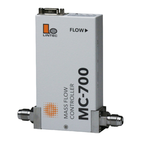
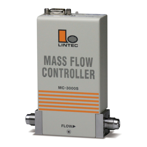
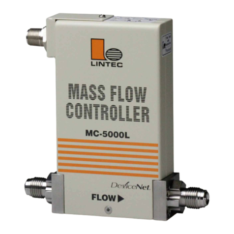
Lintec MC-3000L-TC Series User manual

LN0369E2108E0
Mass Flow Controller
Instruction Manual
MC-3000L-TC Series
Safety Precautions
Incorrect handling may cause death or injury
(1) Before connecting the fittings, check that no damage or defects are found on
the fittings. Make connections properly and make sure that a leak test is
conducted before actual operation to prevent fluid from leaking into the
atmosphere (Hereafter, the measured fluid is called “gas” or “fluid”).
(2) DO NOT apply any fluids corrosive to materials exposed to gas. Corrosion
may cause fluid to leak into the atmosphere. Check the gas type to be used in
advance.
(3) This device is not designed as an explosion proof structure. DO NOT use this
device in a place where explosion-proof structures are required. Doing so may
cause fire or explosion.
Incorrect handlingmayleadtomediumorslightinjury or may
causedamageto,orlossof,facilitiesorequipment
(1) Observe the precautions listed in the WARNING (above).
(2) Strictly observe the electrical specifications. Not doing so may cause fire,
damage to sensors or malfunction.
(3) This device is not designed to be waterproof. DO NOT locate this device
outdoors or in a place where it may be splashed with water. Doing so may cause
fire, trouble, or malfunction of the device.
(4) DO NOT modify this device. It may cause fire or other problems.
(5) While a power supply is applied to the device, +15VDC and -15VDC must be
applied simultaneously. If only +15VDC or -15VDC is applied, electronic
circuits will become unstable and it may cause a malfunction.
(6) This device is not designed to handle hot swap. Please avoid attaching and
removing the power supply connector and interface connector with the power
switched on. Attachment and/or removal with the power on may result in
failure of the device.
(7) This device is a precious device, please handle it carefully. Dropping down or
handling it carelessly will cause damage. Please use assist instrument while
moving or setting the device.
(8) Regular maintenance is recommended for steady use of this device
(Recommended proofreading frequency is once a year).
1. Introduction
This manual explains basic operation of the MC-3000L-TC series (Hereafter, it is
called "MFC"). Please read through this manual and other separatevolumes (Digital
Interface Manual, Special Function Manual, Command Chart) carefully to
familiarize yourself with the features of this device.
2. Summary
The MFC is high performance mass flow controller for gas using thermal flow
sensor and high response solenoid actuator valve.
3. Features
The MFC is the following features.
(1)
LINTEC’s proprietary ambient temperature compensation type flow sensor is carried.
· Low sensor temperature, long-time steady monitor, and few problems such
as degradation of gas to be monitored.
·The effect of ambient temperature is less because the sensor temperature is
kept at the ambient temperature.
·Steady temperature distribution of sensor and high-speed response.
(2) Digital computing system with microprocessor and high-resolution A/D, D/A
converter is carried.
· High functionality.
·By setting of device number (address), multiple devices can be controlled
through a single interface.
· Many additional are provided as standard, e.g., totalizer function, zero adjust,
ramping function.
(3) Universal digital Interface (RS-485).
(4) Small dead space structure using a diaphragm valve.
(5) Superior corrosion resistant sealing materials make maintenance easy. Metal
seals (Au).
(6) Particle-free structure.
(7) By using a metal case and various types of filters, steady operation can achieve
even in an environment of high-frequency noise and stationary magnetic field.
(8) Based on RoHS.
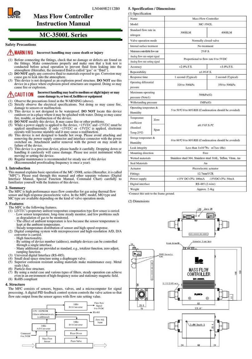
4. Specification / Dimensions
(1) Specification
Name
Mass Flow Controller
Model
MC-3102L-TC
MC-3202L-TC
Standard flow rate in nitrogen
10 SCCM to 5 SLM
~25 SLM
Operatingtemperature
(Hightemperaturepart)
-L
80 to 100 ºC·0 to 80%RH (Condensation should be avoided)
-H
100 to 120 ºC·0 to 80%RH (Condensation should be avoided)
Operatingtemperature
(Control part)
5 to 50ºC·0 to 80%RH
(Condensation should be avoided)
Baking temperature
Below 150ºC
Valve operation mode
Normally closed valve
Internal surface treatment
-TC: No treatment -SC: Precision polishing
Minimum controllable flow rate
2%F.S.
Analog flow rate output signal
Proportional to flow rate 0 to 5VDC
Analog flow rate setting signal
Accuracy
±1.0%F.S.
Repeatability
±0.2%F.S.
Response time
1 second (Typical)
3 seconds (Typical)
Operating differential pressure
50 to 300kPa
150 to 300kPa
Maximum operating pressure
300kPa(G)
Withstanding pressure
1MPa(G)
Storage temperature & Humidity
5 to 50ºC·0 to 80%RH (Condensation should be
avoided)
Leak integrity
Less than 1×10-11Pa · m3/sec (He)
Mounting direction
Free
Wetted materials
Stainless steel 316L, PTFE, Au
Seal Materials
Au
Actuator
Solenoid actuator
Fittings
6.35VCR (124) 6.35SWL (127)
Power supply
+15VDC±3%: 100mA -15VD±3%C: 200mA
Digital interface
RS-485 (2-wire)
Option
B:
Applied to liquefied gas
Weight
Approx. 1.2kg
(Controlling part 0.2kg, High-temperature part 1kg)
·Connect the MFC to the frame ground.
(2) Dimensions
5. Ordering information
MC-3102L –TC - 4JR2 BL0A0 –dd –ee - ff
[1] [2] [3] [4] [5] [6] [7]
[1] Series model MC: Mass Flow Controller Series
MC-3102L: Small flow rate MC-3202L: Large flow rate
[2] Inner surface treatment
-TC: No treatment -SC: Precision polishing
[3] Fitting
4JR1: 6.35UJR106, 4JR2:6.35UJR124
4VR1:6.35VCR106, 4VR2:6.35VCR124, 4SWL :6.35SWL
[4] Optional
B: Applied to liquefied gas, J: Valve is closed at below 2% setting
L: Temperature range 80 to 100℃
H: Humidity range 100 to 120℃
※Default setting is labeled “AA0A0”. Please consult for more information.
[5] Gas type
[6] Full scale flow rate
[7] Flow rate unit
SCCM (0 ºC standard), SLM (0 ºC standard)
6. Connection
(1) Analog interface connector
Mounted connector : D-Sub 9 pin(male)
Pair connector : D-Sub 9 pin(female) (Fixed size of screw : M3)
Pin No.
Single name
Function
1
Valve on-off input (Note1)
+15VDC: OPEN, -15VDC: CLOSE
2
Flow rate output signal 0 to 5VDC
Flow rate output voltage plus side 0 to 5VDC
3
Power supply input +15VDC±3%
Power supply (plus) 100mA
4
Power supply COMMON (Note2)
COMMON ±15VDC
5
Power supply input -15VDC±3%
Power supply (minus) 200mA
6
Flow rate setting signal 0 to 5VDC
(Note1)
Flow rate setting voltage plus side 0 to 5VDC
7
Flow rate output COMMON (Note2)
Flow rate output voltage COMMON
8
Flow rate setting COMMON (Note2)
Flow rate setting voltage COMMON
9
N.C.
N.C.
Note1) Inputimpedance offlow ratesettingsignal is 100kΩ. Valve override impedance is 100kΩ.
Note2) Pin No.4,7,8 are connected internally.
Wirings should be done as shown below in order to remove the effect of potential difference
among the COMMON.
Do not connect. Flowrate settingsignalCOMMON[8],Flowrate outputsignalCOMMON[7],
andPowersupply COMMON[4]in thepowersupplyunit.

(2) Digital interface connector
Mounted connector : RJ-45 Modular jack
Pair connector : RJ-45 Modular plug
Pin No.
Signal name
Function
1
Signal COMMON
RS-485 Signal COMMON
2
Signal COMMON
RS-485 Signal COMMON
3
N.C.
N.C.
4
Signal [- Txd / Rxd ]
RS-485 2-wire system transmitter.
receiver minus signal
5
Signal [+Txd / Rxd ]
RS-485 2-wire system transmitter.
receiver plus signal
6
N.C.
N.C.
7
N.C.
N.C.
8
N.C.
N.C.
7. Alarm functions
This MFC features two alarm modes: alarm A and alarm B. Using a digital
interface, alarm output of the digital connector or LED indicator located on top of
the MFC housing can monitor the alarm status. As alarm settings can only be
changed using digital communication, please carry out necessary changes using
this method. For details, please refer to the Interface Instruction Manual.
Alarm
Set off
LED indicator
A
Setting value≠ flow rate output
Continuous Red
Flow totalizer Alarm level 2
Power supply voltage (+15VDC) drop
Off
B
Voltage of valve control change
Red (every 0.5sec flashing)
Abnormal zero offset (Note3)
Flow totalizer Alarm level 1
Other
Command error
Continuous Red (every 0.5sec flashing)
Normal
-
Green (every 1sec flashing)
8. Initial setting value (factory shipped value)
This MFC is provided with a software switch for operation mode setting. Before
operation, input the necessary data for various functions by using the digital
interface. Details of the functions are described in the special function manual.
Software switch
Available values
Function
Default
Device number
00 to 99
MFC No. Registration
00
Alarm A range
0 to 99 [%]
Setting Alarm A range
5%
Alarm B range
0 to 99 [%]
Setting of Alarm B range
20%
Alarm timer
0 to 99 [seconds]
Setting of Alarm timer
5 seconds
Alarm A output
Enable / Disable
Setting of Alarm A output
Enable
Alarm B output
Enable / Disable
Setting of Alarm B output
Disable
(Note3)
Operation mode
Analog / Digital
Switching of Analog/digital
Analog
Power on mode
Analog / Preset
Switching of Operation mode
in power turning on
Preset
Valve control
C / O / H / S
Close / Open / Hold / Servo
Servo
Control speed
FAST / SLOW
Switching of Response speed
FAST
Control mode
2%Close/2%Hold/ Normal
Control mode switching
(at flow rate setting <2%)
2%Close: Valve Close
2%Hold: 2% Control
Normal: Normal Control
Normal
Conversion factor
0.6666 to 1.500
Conversion factor setting
1.0000
Communication
protocol
9600 to 38400bps
8bit / 7bit
Odd/Even/ None
1bit / 2bit
Baud rate
Character length
Parity
Stop bit
9600bps
7bit
None
2bit
Note3) Zero adjustment error alarms regardless of the “Enable” / “Disable” of the alarm.
·
If a zero-set input of longer than 5seconds is input the Baud rate will be set to 9600bps and other
communication protocols will be returned to initial value (factory shipped value).
9. Operation
(1) Procedure
1) This product is packed in a clean room before shipment. Please break the
seals in a clean room after taking it out of its box.
2) Check the gas type and flow rate, and check the direction of the gas flow
and the MFC before installation.
3) Please set up the high temperature part in a thermostatic bath. When
using a heater, set up the heater in a way of not causing temperature
distribution (When controlling the liquid by vapor pressure, set the
temperature of main body higher than the liquid temperature.
Recommended time: above 20 ºC)
4) Check for gas leaks from the tubing with a helium (He) leak detector.
5) Connect the interface connectors according to the Connector tale.
6) Power requirements are +15VDC: 100mA and -15VDC: 200mA. Check
the voltage, polarity, and capacitance of the power supply voltage.
7) This product consists of a control part and a high temperature part. Be sure
to connect the control part and the high temperature part of the same serial
number before supplying power to the control part. Incorrect procedure
may cause damage to internal equipment. Also, please supply the power
supply, warm up the high temperature part to the specified temperature
range and warm up for 2 hours or more (Please carry out until the main
body temperature reaches the same temperature as the ambient
temperature).
8) Adjust the zero point by pressing the zero adjustment, switch located on
the top of the MFC. Before zero-point adjustment, check that gas is not
being supplied and the device was warmed up for 30 minutes or more in
order to ensure sensor stability.
9) Input the flow rate setting signal and supply gas with required differential
pressure to the MFC. The MFC will begin to control the gas flow in
proportion to the preset voltage. Full-scale voltage is 5VDC. Maximum
input voltage is ±15.5VDC.
10) When the output flow rate signal is used, the tolerance voltage of the
external device should be more than ±15.5VDC. When it’s connected the
output valve may be within the range of the maximum voltage ±15.5VDC.
11) Complete shut off cannot be achieved with the mass flow controller. If
complete shut off is desired, a shut-off valve should be installed.
12) When a highly reactive gas is used, thoroughly purge all foreign matter
from the tubing and the MFC before operation.
13) When contaminated gas is used, install a filter at the equipment inlet.
14) Use the MFC within the range of the operating temperature, and keep it
at the same temperature with the gas. If usedin any environment that does
not meet the above-mentioned requirements, the flow rate cannot be
measured accurately and the device may fail.
15) Donotswitchthepowersupplyonandoffwithinonesecond.Itmaycausefailure.
(2) Valve control signal
The MC features a forced valve open/close input function.
The connector pin No.1 is used to input the internal valve open/close signal.
By inputting this signal, a forced opening/closing of the internal valve can be
performed without depending on the value of the flow rate preset signal.
When +15VDC is input: fully open
When –15VDC is input: fully closed.
(3) Conversion factor
TheMFC ispresetbased on thekind of gas and the flow rate. If a gasthat is not
specified issupplied, thecontrolled flow rate may be different fromthe actual flow rate.
This difference is called a conversion factor, and is normally represented by a ratio
with N2. When gas B is fed into the MFC, which was calibrated with gas A, the
controlled flow rate is shown below.
Theaccuracy of this value maybe decreased ifthe characterof the gas is greatly
different. Also, thevalue of the MFC has been adjusted based onthe viscosity and
density ofthegas,thereforeifa gasother than thecalibrationgasisapplied,the
operating pressure range may be altered. The conversion factor can be set atany desired
value, with an operating rangeof 0.6666 to 1.5000. Iftheconversion factorvalue
exceedsthis range, theoperationoftheMFCbecome unstable.Theaccuracyisdifferent
from the standard specifications of the MFC, whenthe conversion factor is changed.
(4) Digital interface
The MFC features the RS-485 serial digital interfaces. Many special functions
can be employed using the digital interfaces. Please refer to other manuals
(Digital Interface Manual, Special Function Manual, Command Chart).
(5) For general gas control
1) The heat exchange of gas should be made thoroughly to prevent any
difference between the gas temperature and the temperature of the main
body. When there is a big difference between them, errors occur in the
controlled flow rate.
2) Do the temperature control to prevent rapid changes in the temperature of
main body as well as the gas temperature.
3) When adding a heater to the main body, install the heater in a way of not
causing the temperature gradient of the main body.
4) The temperature of the main body should not exceed 120ºC.
(6) For liquid control by vapor pressure
1) Check whether the vapor pressure of the liquid is sufficient (and the
temperature is appropriate).
2) Check whether there is dissolved gas in the liquid (or whether the vacuum
degassing has been made thoroughly).
3) Check whether the surface area of liquid level in the tank is proportionate to
the flow rate in use (If the surface area is small, the control becomes unstable
due to changes in the temperature distribution and vapor pressure. In some
cases, it may become hard to obtain the required flow rate).
4) Do not heat up the liquid locally. Just as the above-mentioned, doing so may
cause a great change in temperature distribution.
5) Control the temperature of tubing and MFC to make a gradual rise in
temperature at the downstream side.
6) If the used materials have reactivity with moisture and oxygen, thoroughly
purge all foreign matter from the tubing and the MFC by baking and
vacuuming before operation.
7) Be sure to do baking and vacuuming after using to keep no residual gas
inside. If it is left with residual gas inside for a long time, it may become very
hard to liquefy again, and the MFC cannot be reused.
8) In the case of internal liquefaction due to the temperature management bias,
after long hours of purging and vacuuming, it can be used again as long as it
has not been corroded by liquefaction.
10. Product warranty
(1) Period
This product is guaranteed for a period of 1 year from date of shipment. Defects
are repaired according to the following regulations.
(2) Scope
Warranty coverage is restricted to this product only. Any other damage caused
by this product is not covered.
(3) Disclaimer facts
The following repairs are not covered by the warranty:
1) Failure caused by by-product of fluid used.
2) Failurecausedbymisuse(includingcarelessoperation)orincorrectrepairormodification.
3) Failure caused by dropping after purchasing.
4) Failure caused by a natural disasters.
Even if thewarranty period is still in effect, the following items may not be repaired.
1) When the kind of fluid used in the product is unclear.
2) The product is returned with fluid remaining inside and safety cannot be
confirmed.
The MFC is a precision instrument. Control may become unstable if electric
noise, temperature change of fluid, pulsation of fluid pressure etc. occurs.
Please be forewarned.
This instruction manual is subject to revision without notice.
http://www.lintec-mfc.co.jp
CorporateHeadquarters
4-1-23Sekinotsu,OtsuCity,ShigaPref.520-2277,Japan
TEL. +81-(0)77-536-2210FAX.+81-(0)77-536-2215
TokyoBranchOffice
3FHattoriBuild.,4-30-14YotsuyaShinjyuku-kuTokyo160-0004,Japan
TEL. +81-(0)3-5366-2801FAX.+81-(0)3-3341-3513
Other Lintec Controllers manuals
