Lippe Lift T80 User manual

Installation manual Konstanz DC 1/25 Version 8.0 Last update: 2/15/10
Key word directory.......................................................................................................…. 1
Pre-conditions.............................................................................................................….. 2
Transport and interim storage...................................................................................…… 3
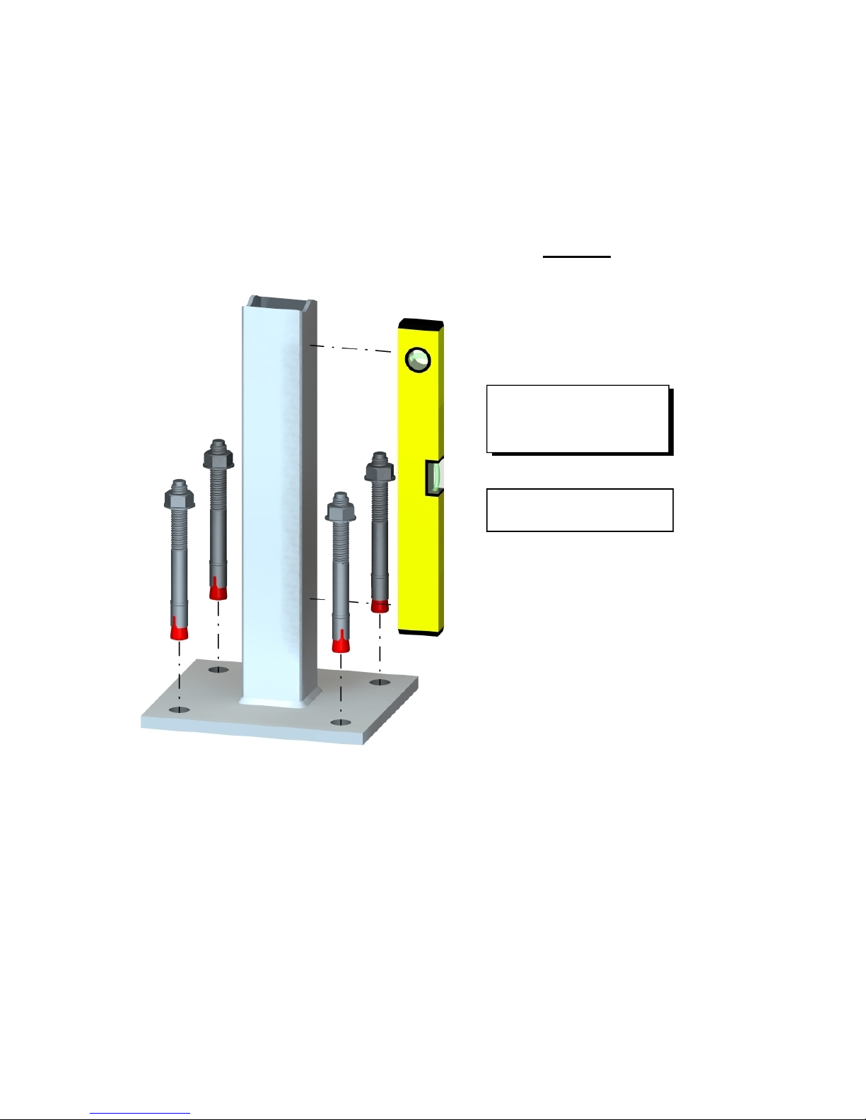
Setting supports ...........................................................................................................… 3
Setting up track....................................................................................................…….. 4
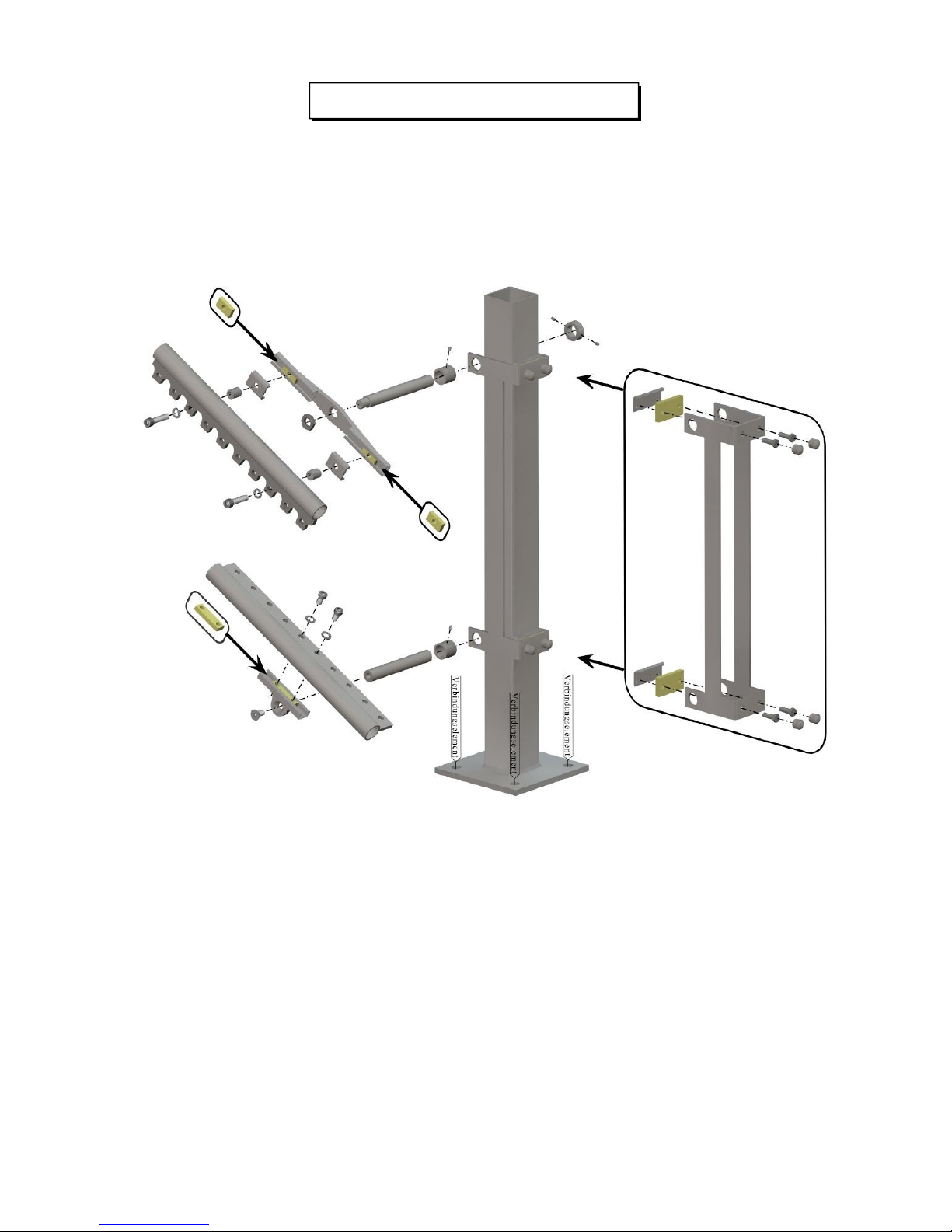
Fastening of track supports......................................................................................…. 5
Example of upper and lower stopping points .............................................................. 6
Fastening of track wall (concrete (B25), steel, other)..................................………… 7
Fastening of the Halfen track-wall...........................................................................…. 8
Rotate roller heads, drive the track to the platform...................................................…… 9
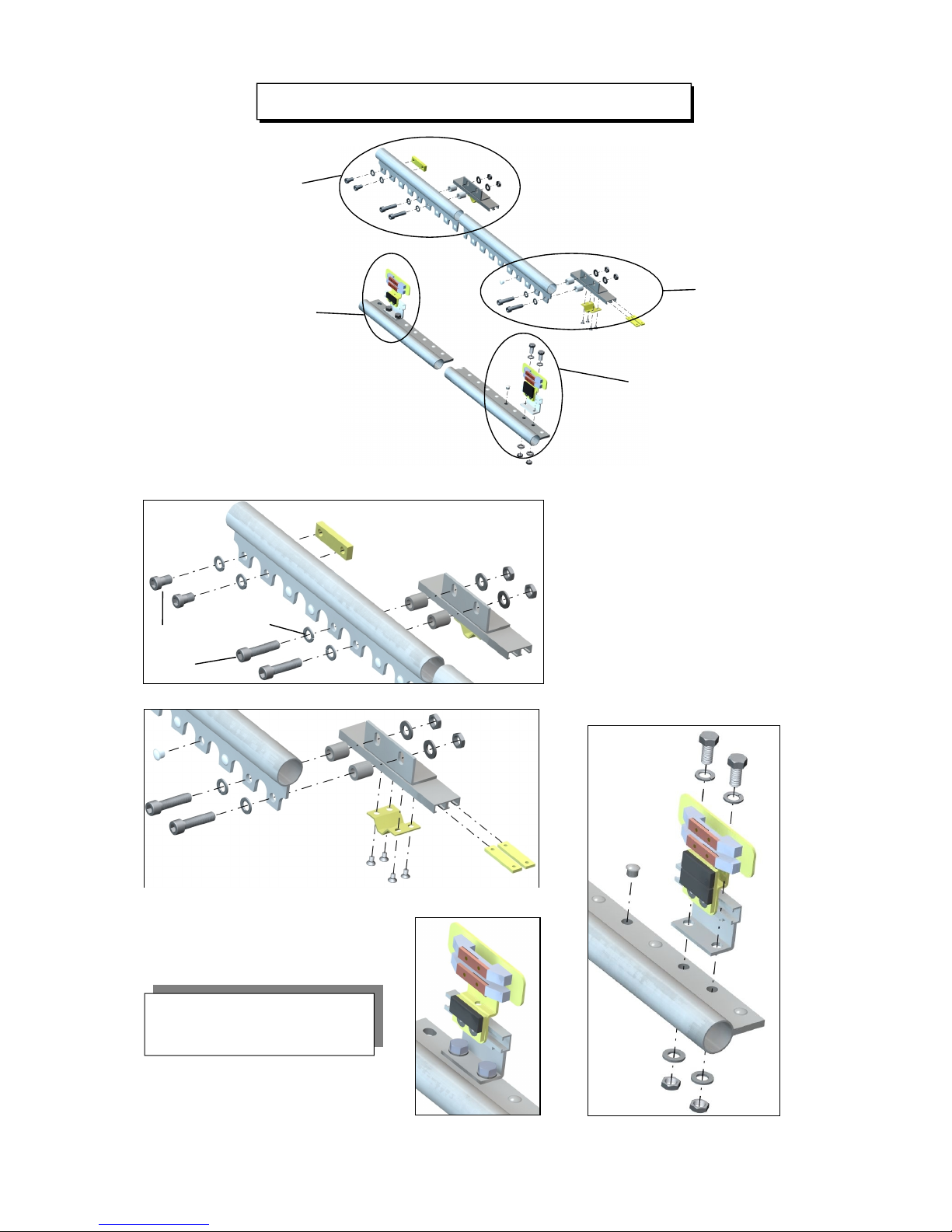
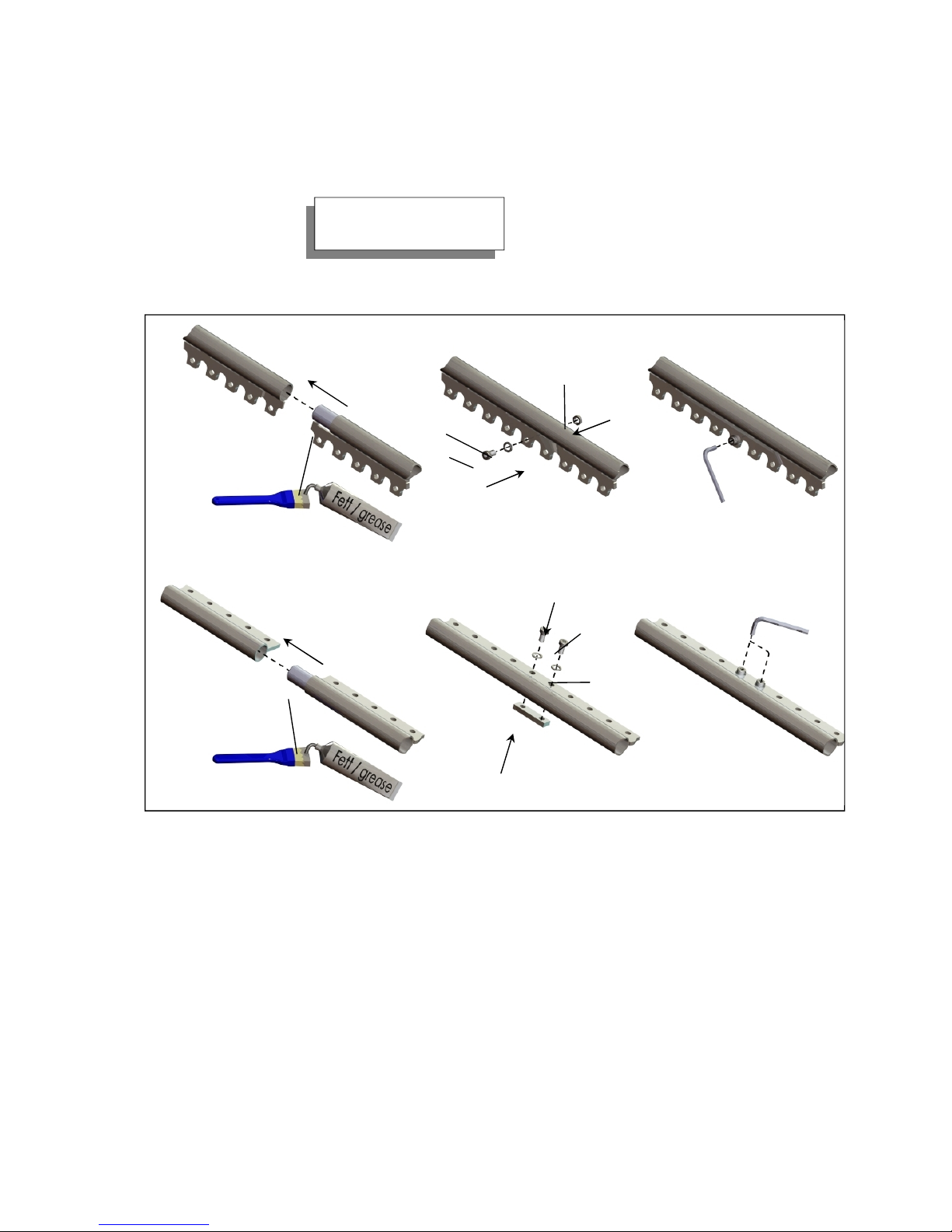
Connect track parts with one another....................................................................….. 10
Potential equalization....................................................................................................... 11
External command giver................................................................................................... 11
Loading devices................................................................................................................. 11
Set stopping points...................................................................................................…... 13
Overrun fuse........................................................................................................……… 14
Screwing of the roller sets.....................................................................................……. 14
Sensitive surfaces under the platform frame.................................................................… 15
Track paneling and fall protection…..............................................................………….. 16
Shunt switch bar..............................................................................................………… 17
Concluding work and instruction of the operator ........................................……………. 17
Disassembly...................................................................................................................... 18
Notes about disposal........................................................................................................ 18
Appendix I: Maximal dimensions for assembly........................................................... 19
Appendix II: Free-standing supports (on the foundation).......................................... 20
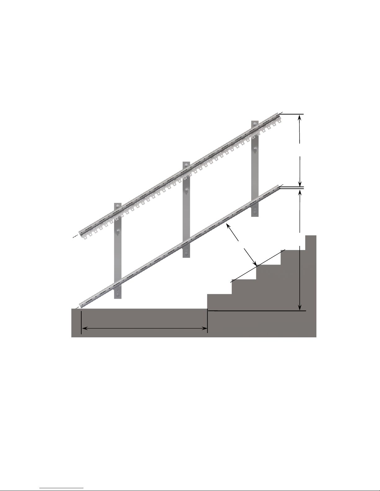
Appendix II: Caught supports (on steps).............................................................…… 20
Recommendation for pin selection KONSTANZ........................................................ 21
Loading forces............................................................................................................…. 24
Key word Page

Installation manual Konstanz DC 2/25 Version 8.0 Last update: 2/15/10
Assembly manual for stair inclined lifts T80
The assembly may only be performed by qualified technical personnel!
The following work may only be performed by qualified personnel:
Assembly work
Adjustment and setup work
Maintenance work
Malfunction search/removal
Qualified personnel are persons who
- who are familiar with the machine function
- have been trained about the functioning
- have read and understood the operating, assembly and service manuals
- are clear about the hazards of the machine (and its components)
- recognize and understand the relationship of the mechanical components
- recognize and understand the relationship of the electrical components
- possess the appropriate tools/measurement devices and can use them
- have sufficient knowledge of German or English for understanding
During any work on the machine, please observe:
- Do not make the machine accessible to other persons with increased hazard potential
(disassembled paneling parts, protective devices,…)
- Risk of tripping due to opened machine, avoid tools, power cables etc. lying around
- The hazard potential of the machine may not be increased after work on the machine.
- Parts of the machine which are not firmly connected with the construction/rail must be secured
against falling over.
The safety notes in the operator manual must be observed!!

Installation manual Konstanz DC 3/25 Version 8.0 Last update: 2/15/10
1Check whether the on-site measures have been carried out (e.g. removal of the railing, chamfer
beveling, removal of the opposite-lying hand rail, current laying etc.).
2In order to avoid damages, only the parts currently needed should always be unpacked. The
unpacked parts of the installation should be temporarily stored on the foam which is delivered
with them. The platform can be attached to the cabinets (as far in as possible) and thus
transported.
3.) Place and dowel the supports (in case of support assembly) in accordance with the installation
drawing. In the process, make sure that the supports are attached vertically (Water level).
Dowel type to be used:
Appendix II
Important !!
Absolutely observe
appendix 1 on page 19 !

Installation manual Konstanz DC 4/25 Version 8.0 Last update: 2/15/10
4.) Position the platform in accordance with the assembly drawing and guide the lower track pipe
into the lower roller set (Observe item 6 on page 9). Arrange the lower track pipe in accordance
with the displayed sketch. Dimension Y is takes precedence over dimension Z. Dimension Z
gives the dimension between the lower edge of the lower track pipe (which as a rule has a length
of 1900 mm) and the level of the lower stop (floor). Possibly this dimension cannot be measured
directly on site because steps exist there. Then an auxiliary dimension should be computed on
site (reduced dimension Z) by subtracting the respective step height from dimension Z. The
auxiliary dimension then gives the vertical clearance between the end of the lower track pipe
(lower edge) and the step which lies perpendicular below it.
If the dimensions agree with those of the installation drawing, the lower rail should be fastened
either to the wall(see page7) or on the supports(see page 5) (Make sure that the lower cap is
present on the pipe). Only when the lower rail is completely installed will the upper rail be
inserted and mounted. The maximum clearance between the individual fastening points is
described in appendix 1 on page 19.
In the case of wall mounting on concrete/steel or by means of threaded rods, the fastening plates
should be attached as displayed on the next page. Here, keep the maximum clearances of the
fastening plates between each other as displayed in appendix 1(Page19).
585
Z
Y
X

Installation manual Konstanz DC 5/25 Version 8.0 Last update: 2/15/10
Example of a support fastening
Other manuals for T80
3
Other Lippe Lift Stairlift manuals