Lippert Components Level Up LCD Travel Trailer User manual

Level Up® LCD
Travel Trailer
OWNER'S MANUAL
DISCONTINUED

Rev: 10.29.18 Page 2 CCD-0001532
Introduction
The manual is for travel trailer applications only.
Level Up® is an automatic leveling system. This hydraulic system is equipped with 8K aluminum leveling
jacks. The jacks in the Level Up system work in pairs. A 12V DC electric motor drives a hydraulic pump
that moves fluid through a system of hoses, fittings and jacks to level and stabilize the trailer. Mechanical
portions of the system are replaceable. Contact Lippert Components, Inc. to obtain replacement parts.
Additional information about this product can be obtained from lci1.com/support or by downloading the
free myLCI app. The app is available on iTunes® for iPhone® and iPad® and also on Google Play™ for Android™
users.
iTunes®, iPhone®, and iPad® are registered trademarks of Apple Inc. Google Play™ and Android™ are
trademarks of Google Inc.
TABLE OF CONTENTS
Introduction 2
Safety 3
Prior to Operation 4
Operation - Level Up LCD 4
Unhitching Instructions 4
Auto Level 4
Touchpad Diagram 5
Hitch Recognition 6
Manual Operation 6
Maintenance 7
Fluid Recommendation 7
Zero Point Calibration 7
Troubleshooting 8
Manual Override 9
DISCONTINUED

Rev: 10.29.18 Page 3 CCD-0001532
Lippert Components Inc. recommends that a trained professional be employed to change the tires
or perform other service on the trailer. Attempts to change the tires or perform other service while
trailer is supported solely by the LCI Level Up automatic leveling system could result in death, serious
personal injury or severe product or property damage.
Safety
The “WARNING” symbol above is a sign that an installation procedure has a safety risk involved and
may cause death, serious personal injury or severe product or property damage if not performed
safely and within the parameters set forth in this manual.
Make sure the trailer is properly supported before performing any maintenance or repair work.
Follow the trailer manufacturer's recommendations for lifting and supporting the unit. Failure to do
so may result in death or serious injury.
Moving parts can pinch, crush or cut. Keep clear and use caution.
DISCONTINUED

Rev: 10.29.18 Page 4 CCD-0001532
Prior to Operation
The leveling system shall only be operated under the following conditions:
1. Make sure to park the trailer on solid, level ground.
2. Make sure all jack landing locations are cleared of debris and obstructions and also free of depressions.
3. When parking the trailer on extremely soft surfaces, utilize load distribution pads under each jack.
4. Keep people and pets clear of the trailer when operating leveling system.
5. Make sure to keep hands and other body parts clear of fluid leaks. Oil leaks in the leveling system may
be under high pressure and can cause serious skin-penetrating injuries.
6. Make sure the battery of the trailer is fully charged or the trailer is plugged into shore power prior to
attempting to operate the system.
NOTE: Level Up requires a minimum of 12V DC from the battery for proper operation.
Operation - Level Up LCD
Unhitching Instructions
NOTE: Prior to unhitching from the tow vehicle, make sure the trailer is parked on a level surface and the
tires are chocked.
1. Press the POWER button (ON/OFF) (Fig. 1K) to turn system on. The LCD screen (Fig. 1E) will light up.
2. Press UP (Fig. 1A) or DOWN arrow (Fig. 1B) to scroll through selections until MANUAL MODE is
displayed (Fig. 2).
3. Press ENTER button (Fig. 1C).
4. Press FRONT button (Fig. 1G) to extend front jacks to the ground until the trailer is unhitched from the
tow vehicle.
NOTE: The Power Tongue Jack should only be used when storing the trailer.
Auto Level
For the hitch recognition feature to function, the auto-level sequence MUST be started with the front of the
trailer above level. The Power Tongue Jack MUST be retracted prior to starting auto-level sequence. There
will be an LCD alert displayed if the Power Tongue Jack is not retracted (Fig. 3).
After unhitching from the tow vehicle, press Auto Level (Fig. 1F). Auto leveling will execute as follows:
NOTE: Pressing any button during an auto-level sequence will abort the auto-leveling cycle.
1. Front jacks retract, lowering the front of the trailer below level, stopping, then lifting the front end to
level the trailer front to back.
2. The rear left side leveling jack extends and raises the roadside of the trailer.
3. The rear right side leveling jack extends and raises the curbside of the trailer, beginning side-to-side
leveling.
4. The front jacks extend to complete the leveling cycle.
NOTE: Additional left-to-right or front-to-back leveling may occur if the controller deems necessary.
NOTE: If the auto-level sequence does not happen as stated above, determine if there is proper manual
function in all zones.
DISCONTINUED

Rev: 10.29.18 Page 5 CCD-0001532
LCD Touchpad Features
Callout Description
A UP Arrow - Scrolls up through the menu on LCD.
B DOWN Arrow - Scrolls down through the menu on LCD.
C ENTER - Activates modes and procedures indicated on LCD.
D RETRACT - Places leveling system into retract mode while in manual mode only.
E LCD Display - Displays procedures and results.
F AUTO LEVEL - Places leveling system into auto level mode.
G FRONT Jack Button - Activates both front jacks.
H LEFT Jack Button - Activates left leveling jack(s) in manual mode.
I RIGHT Jack Button - Activates right leveling jack(s) in manual mode.
J REAR Jack Button - Activates rear leveling jacks in manual mode.
K POWER Button (ON/OFF) - Turns leveling system on and off.
Fig. 1
Touchpad Diagram
A
BE
F
CG
DH
I
J
Fig. 2
PN 234802 - Black
Fig. 1
F
PN 421484 - Gray
Fig. 3
KA
B
CE
D
K
H
G
I
J
DISCONTINUED

Rev: 10.29.18 Page 6 CCD-0001532
Hitch Recognition
1. Turn on touchpad.
2. Press the LEFT and RIGHT jack buttons simultaneously (Fig. 1H and 1I).
3. The front of the trailer will raise to the height where the auto-level sequence was started.
NOTE: If the auto-level sequence was started with the front of the trailer in a below-level condition,
the hitch recognition will not function and the LCD will display Feature Disabled. For the hitch
recognition feature to function, the auto-level sequence MUST be started with the front of the
trailer above level.
4. Connect tow vehicle and make sure travel trailer and hitch are connected and locked.
5. Press the UP arrow (Fig. 1A) until AUTO RETRACT appears in the LCD screen.
6. Press the ENTER button (Fig. 1C). The system will immediately retract all jacks.
Manual Operation
1. Front jacks
NOTE: The front jacks will operate manually any time system is on except in AUTO MODE.
A. Press the POWER button (ON/OFF) (Fig. 1K) to turn system on.
B. Press the UP arrow (Fig. 1A) once or until screen reads MANUAL MODE (Fig. 2).
C. Press the ENTER button (Fig. 1C) once while screen reads MANUAL MODE (Fig. 2).
D. Press the FRONT jack button (Fig. 1G) to extend front jacks.
E. Press the RETRACT button (Fig. 1D) and the LED (Fig. 4) comes on.
F. Press the FRONT button (Fig. 1G) to retract front jacks.
NOTE: If the LED indicator light (Fig. 4) is on, jacks will retract. If the LED indicator light is off, jacks will extend.
G. Press the POWER button (ON/OFF) (Fig. 1K) to turn system off.
H. After three minutes of inactivity, the system will automatically turn off.
Fig. 4
2. Level Up leveling jacks - EXTEND
A. Press the POWER button (ON/OFF) (Fig. 1K) to turn system on.
B. Press the UP (Fig. 1A) or DOWN arrows (Fig. 1B) to scroll through selections until MANUAL MODE is
displayed.
C. Press the ENTER button while MANUAL MODE is displayed (Fig. 2).
NOTE: By pressing the RIGHT jack button, the curbside Level Up jacks operate. By pressing the LEFT jack
button, the roadside Level Up jacks operate. Follow similar procedures for front and rear jacks.
NOTE: To extend, the RETRACT button's LED light (Fig. 4) should be off.
3. Level Up leveling jacks - RETRACT
A. Press the RETRACT button and the LED indicator light (Fig. 4) will come on.
B. Press the REAR jack button to retract all Level Up jacks.
NOTE: The side-to-side movement in manual mode is limited to five degrees of tilt.
Fig. 4
PN 234802 - Black PN 421484 - Gray
DISCONTINUED

Rev: 10.29.18 Page 7 CCD-0001532
Zero Point Calibration
The Zero Point is the programmed point that the trailer will return to each time the auto-level feature
is used. The Zero Point must be programmed prior to using the auto-level feature to ensure the proper
operation of the system.
NOTE: Prior to starting this procedure, double check all connections on the controller, jacks and touchpad.
1. Manually run the jacks to level the trailer.
A. Manual leveling is best achieved by placing a level in the center of the trailer and leveling it both
front to back and then side to side.
B. See Manual Operation section for instructions on how to manually operate the system.
2. After the trailer has been leveled, turn off the touchpad.
3. With the touchpad off, press and release the FRONT jack button (Fig. 1G) 10 times, then press and
release the REAR jack button (Fig. 1J) 10 times.
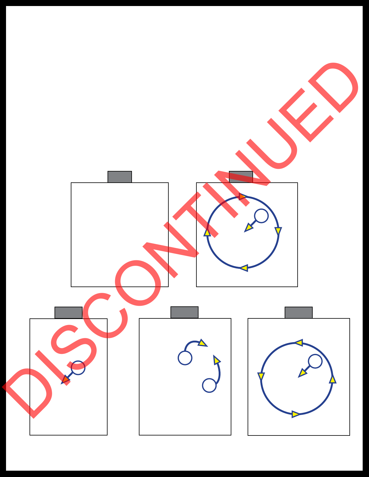
4. The touchpad will flash and beep and the LCD display will read ZERO POINT CALIBRATION ENTER to
set, Power to Exit (Fig. 5).
5. To set the current position as the zero point, press the ENTER button (Fig. 1C).
A. The LCD display will read Zero point stability check (Fig. 6).
B. The LCD display will read Zero point set successfully once process has been completed (Fig. 7).
C. The system will set this point as its level state and the touchpad will turn off.
Fig. 5 Fig. 6 Fig. 7
Maintenance
1. Each month, check that the fluid level is within 1/4" of the fill spout lip while leveling jacks and slide-
outs are fully retracted.
NOTE: Always fill the reservoir with the leveling jacks and slide-outs in the fully retracted position. Filling
the reservoir when leveling jacks and slide-outs are extended will then cause the reservoir to
overflow into its compartment when jacks and slide-outs are retracted.
2. Maintain battery at full capacity.
3. Inspect and clean all power unit electrical connections prior to the first use of the trailer at the start of
the traveling season and prior to storing the trailer. If corrosion is evident, clean all corrosion with a
wire brush and apply dielectric grease to the connections.
4. Remove dirt and road debris from leveling jacks as needed.
5. If leveling jacks are down for extended periods, LCI recommends spraying exposed jack rods with a
silicone lubricant every three months for protection. If the trailer is located in a salty air environment,
spray the rods every four to six weeks.
Fluid Recommendation
The Lippert Electronic Leveling System is pre-filled, primed and ready to operate direct from the
manufacturer. Type “A” Automatic Transmission Fluid (ATF) is utilized and will work. ATF with Dexron III® or
Mercon 5® or a blend of both is recommended by Lippert Components, Inc.
In colder temperatures (less than 10° F) the jacks may extend and retract slowly due to the fluid’s molecular
nature. For cold weather operation, fluid specially formulated for low temperatures may be desirable. For a
list of approved fluid specifications, see TI-188. Or go to https://www.lci1.com/towable-br-level-up/support-
towable-level-up-br-touch-pad/, click on the Technical Information Sheets tab, then select TI - 188: Hydraulic
Operation Fluid Recommendation from the listed documents.
DISCONTINUED

Rev: 10.29.18 Page 8 CCD-0001532
Troubleshooting
Error Display In LCD Screen
NOTE: To clear an Error Code, press the ENTER button (Fig. 1C). If the error remains, the Error Code will
appear again.
Error Codes
LCD Message What's Happening? What Should Be Done?
EXCESS ANGLE
Controller not properly secured. Check and secure controller
placement.
Excessive angle reached during auto
operation. Relocate the trailer.
EXCESSIVE ANGLE
Controller not properly secured. Check and secure controller
placement.
Excessive angle reached during manual
operation. Relocate the trailer.
FEATURE DISABLED
Front of trailer below level when
starting Auto Level process (only when
trying to initiate hitch recognition).
Push the FRONT button to raise
the trailer to hitch height and
connect to tow vehicle.
Touchpad power not cycled between
consecutive leveling operations.
Turn touchpad off and then back
on to reset the system.
Zero point not set. Set zero point.
LOW VOLTAGE Battery voltage dropped below 9.5V.
Check wiring - repair or replace.
Test battery voltage under load -
charge or replace.
OUT OF STROKE Jack has reached maximum stroke
length and is unable to lift.
Check disposition of jacks and/or
relocate the trailer.
EXTERNAL SENSOR Bad connection or wiring from the
controller to the rear sensor.
Replace or repair connection to
rear remote sensor.
JACK TIME OUT Time limit exceeded for the requested
auto operation. Check disposition of jacks.
AUTO LEVEL FAIL
Unable to auto level due to uneven
ground.
Check disposition of jacks and/or
relocate the trailer.
Unable to auto level due to zero point
being set incorrectly. Reset zero point.
BAD CALIBRATION Sensor calibration values are out of
range. Replace controller.
INTERNAL SENSOR Internal sensor problem. Replace controller.
FUNCTION ABORTED
The user pressed a button on the
touchpad during an automatic
operation.
Restart automatic operation and
then refrain from pressing any
buttons on the touchpad.
DISCONTINUED

Rev: 10.29.18 Page 9 CCD-0001532
Manual Override
The LCI Level Up Automatic Leveling System can be manually operated with an electric drill. In the event of
electrical or system failure, this manual method of extending and retracting the jacks can be used. See the
instructions below.
NOTE: Unhook the power unit motor from the power source prior to attempting the manual override
procedure.
1. Locate the valves that are paired with the leveling jacks to be manually overridden. Leveling jack valves
are located on the manifold (Fig. 8).
2. Using a 5/32” hex wrench, open the valve by turning the manual override set screw clockwise (Fig. 9A).
3. Remove protective label (Fig. 10A) from power unit to reveal the manual override coupler.
4. Using an electric drill with a 1/4" hex bit, insert the hex bit into the manual override coupler to manually
operate the Level Up system (Fig. 11).
A. Run the drill forward (clockwise) to retract the leveling jack (Fig. 11A).
B. Run the drill in reverse (counterclockwise) to extend the leveling jack (Fig. 11B).
5. Make sure to turn the manual override set screw on the valve (Fig. 12A) back to the counterclockwise
position after extending or retracting the jacks.
A
A
A
A
B
Fig. 8 Fig. 9
Fig. 10 Fig. 11 Fig. 12
DISCONTINUED

The contents of this manual are proprietary and copyright protected by Lippert Components, Inc. (“LCI”).
LCI prohibits the copying or dissemination of portions of this manual unless prior written consent from an
authorized LCI representative has been provided. Any unauthorized use shall void any applicable warranty.
The information contained in this manual is subject to change without notice and at the sole discretion of LCI.
Revised editions are available for free download from lci1.com.
Please recycle all obsolete materials.
For all concerns or questions, please contact
Lippert Components, Inc.
DISCONTINUED
Table of contents
Other Lippert Components Industrial Equipment manuals

Lippert Components
Lippert Components Happijac User manual

Lippert Components
Lippert Components SOLIDSTEP 2.0 User manual

Lippert Components
Lippert Components Solera 728810 Installation instructions

Lippert Components
Lippert Components Power Gear 82-L0356 User manual

Lippert Components
Lippert Components Equa-Flex Triple Axle Installation instructions