Lippert Power Bimini Master User manual

Power Bimini Master
OWNER'S MANUAL

Rev: 08.30.22 Page 2 CCD-0006500
TABLE OF CONTENTS
Introduction 3
Safety 4
Power Bimini Featuresif so equipped 5
Complete Quick-Connect Bimini Systemif so equipped 10
Bimini Top Positions 11
Fully Closed (Down)—Towing Position 11
Radar—For Water Use Only 12
Fully Opened (Up)—For Water Use Only 12
Operation 13
Helm-mounted Switchif so equipped 14
Key-Fob (Remote Control)if so equipped 18
Programming Additional Key-Fobs (Remotes)Optional 20
Touch Controller or Appif so equipped 21
High Speed Mesh Topif so equipped 36
Front Shade Extensionif so equipped 37
Courtesy Lightif so equipped 39
Speakersif so equipped 39
Adjustable Front Support Strapsif so equipped 40
Front Support Arms—if so equipped 40
Troubleshooting 43
Manual Override 46
Maintenance 49
Fabric Care 49
Front Support Arms 49
Trailering (Towing) 49
Storage or Storm Position 49
Winter Storage 49
Wiring Diagrams 50
Helm Switch to Actuators 50
Helm Switch and Key-Fob 51
Helm Switch to Actuators and Speakers 52
QC Controller to Actuators 53
QC Controller to Actuators and Speakers 54
Notes 55

Rev: 08.30.22 Page 3 CCD-0006500
Introduction
The Power Bimini delivers improved sun protection and on-board comfort with an automated telescoping
boat shade that can be easily operated by a helm-mounted momentary switchor, if so equipped, by a
two-button touch-sensitive controller, a Bluetooth® compatible app or by the convenience of a key-fob
remote.
NOTE: A helm-mounted switch and a touch-sensitive controller are NOT compatible. Only one type
of control can be used. Determine which type of control is installed before operating the power
biminisystem.
The Power Bimini system can be equipped with several features:
• Key-Fob (remote control)
• Touch-sensitive controller (Touch Controller)
• High-speed mesh top
• Front shade extension
• Courtesy light
• Speakers
• Adjustable front support straps
• Front support arms
• Complete quick-connect (QC) bimini system
This manual covers the operation of the various available power bimini features. To learn about the
operation of any installed feature, refer to its section listed under the Table of Contents.
Additional information about this product can be obtained from lippert.com/support or by downloading
the free LippertNOW app. The app is available on Apple App Store® for iPhone® and iPad® and also on
Google Play™ for Android™ users.
Apple App Store®, iPhone®, and iPad® are registered trademarks of Apple Inc.
Google Play™ and Android™ are trademarks of Google Inc.
For information on the assembly or individual components of this product, please visit:
https://support.lippert.com/marine-products/ .
NOTE: Images used in this document are for reference only when assembling, installing and/or operating
this product. Actual appearance of provided and/or purchased parts and assemblies may differ.

Rev: 08.30.22 Page 4 CCD-0006500
Safety
Read and understand all instructions before installing or operating this product. Adhere to all safety labels.
This manual provides general instructions. Many variables can change the circumstances of the instructions,
i.e., the degree of difficulty, operation and ability of the individual performing the instructions. This
manual cannot begin to plot out instructions for every possibility, but provides the general instructions,
as necessary, for effectively interfacing with the device, product or system. Failure to correctly follow the
provided instructions may result in death, serious personal injury, severe product and/or property damage,
including voiding of the Lippert limited warranty.
The "WARNING" symbol above is a sign that a procedure has a safety risk involved and may cause
death or serious personal injury and/or severe product or property damage if not performed safely
and within the parameters set forth in this manual.
Failure to follow instructions provided in this manual may result in death, serious personal injury
and/or severe product and property damage, including voiding of the component warranty.
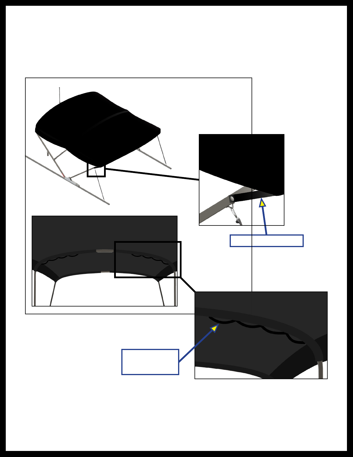
Do NOT fully open the bimini frame without the canvas top installed. Opening the bimini frame
without the canvas top installed will result in severe product damage. Only fully open the bimini
frame with the canvas top installed.
The 6 Amp auto-reset circuit breaker used on any Power Bimini System that does NOT use the touch-
sensitive controller MUST be protected by a 15 Amp auto-reset circuit breaker or a 30 Amp fuse.
The 6 Amp auto-reset circuit breaker provides protection for the Power Bimini System and NOT for
the entire craft's electrical wiring system. Do NOT use a replacement fuse less than 30 Amps. Circuit
breakers and fuses do NOT operate the same and are NOT interchangeable.
Do NOT open or operate the top in excessively high winds. Having the top open or operating the
top in high winds, regardless if the boat is in motion or anchored, can cause serious damage to the
top's framework, which could cause severe product and/or property damage, including serious
personalinjury.
Do NOT operate the top while the boat is in motion. Operating the top while the boat is in motion
can cause serious damage to the top's framework, which could cause severe product and/or property
damage including serious personal injury.
Do NOT trailer or tow the boat without the protective boot properly installed on the top and without
the top in its full down position. Trailering or towing the boat without the top in its full down position
and without the protective boot properly installed can cause serious damage to the top's framework,
which could cause severe product and/or property damage, including serious personalinjury.

Rev: 08.30.22 Page 5 CCD-0006500
The “CAUTION” symbol above is a sign that a safety risk is involved and may cause personal injury
and/or product or property damage if not safely adhered to and within the parameters set forth
in this manual.
Always wear eye protection when performing service, maintenance or installation procedures.
Other safety equipment to consider would be hearing protection, gloves and possibly a full face
shield, depending on the nature of the task.
All electrical wiring harnesses shall be loomed and secured to prevent possible damage and
installed in accordance with the latest ABYC (American Boat and Yacht Council) electrical standards,
E11 and S31
Do NOT exceed 15 mph when front shade extension is deployed. Exceeding maximum speed
limit with front shade extension deployed can cause damage to the extension and void product
warranty.
Moving parts can pinch, cut or crush. Keep clear and use caution.
Power Bimini Featuresif so equipped
The following power bimini feature illustrations identify the location of the system's key features, if
soequipped.
NOTE: The fabric top is not shown in some images for clarity.
NOTE: The fence railing is shown for illustrative and orientation purposes only. Boat fencing and railings
are NOT included in the Power Bimini system.
Securing straps are provided to prevent undue billowing of the bimini top and for the attachment of
accessories. There are three different types of straps:
• Corner Straps – two at each corner of the front leading edge. These are used to prevent the top from
moving side-to-side and to secure it when prepping the top for storage in the boot.
• Front Straps – two front adjustable straps are connected from the front frame to the pontoon rail.
NOTE: The bimini is rated for 45mph with the front straps in-place and only 25mph without the front
straps secured.
• Changing Room Attachment Straps – four loops under the canopy on either side of the middle frame (eight
loops total) for attaching a changing room.
NOTE: Make sure the corner securing straps are in place when installing the boot or operating the
biminitop.
The front shade extension connects to the open zipper end of the bimini's storage pocket.
NOTE: When the bimini front shade extension is open the maximum speed rating is 15 mph.
NOTE: Front support straps are NOT used when the front shade extension is in use. Disconnect front
support straps and stow them in the bimini top's front zippered storage pocket before deploying
the front shade extension. If so desired, reconnect the front support straps after the front shade
extension has been disconnected andstowed.

Rev: 08.30.22 Page 6 CCD-0006500
Port-side
Actuator
Actuator
Mounting Cap
Starboard-side
Actuator
Touch Controller
(if equipped)
Fence Railing
Fence Railing
Navigation Light
Front shade extension stanchions and tie-down straps are folded, rolled up inside the shade fabric and
tucked into the bimini's front pocket forstorage.
Two adjustable front support straps provide additional tension to the bimini top to help prevent vibration of
the frame in high speed boating conditions. They are easily deployed and stored.

Rev: 08.30.22 Page 7 CCD-0006500
Front Frame
Rear Frame
Middle Frame
Courtesy Light
Standoff
Fence Railing
Fence Railing
Adjustable
Front Support
Straps

Rev: 08.30.22 Page 8 CCD-0006500
Front Securing Straps
Optional
Accessory Loops

Rev: 08.30.22 Page 9 CCD-0006500
Stanchions
Quick Release
Hinge
Boat Railing
Saddle
Strap
Front Shade
Extension
Tie-down
Straps

Rev: 08.30.22 Page 10 CCD-0006500
Complete Quick-Connect Bimini Systemif so equipped
Front Shade
Extension
Mesh Top
Speakers
Controller
Power Bimini
Actuators and Frame
Front
Support Arm
Front
Support Arm

Rev: 08.30.22 Page 11 CCD-0006500
Vari-pitch—For Water Use Only
Remove protective boot. Maximum water speed limit 5 MPH.
Used for improved shade protection from late-day sun.
Bimini Top Positions
Fully Closed (Down)—Towing Position
Install protective boot.
Do NOT trailer or tow the boat without the protective boot properly installed on the top and without
the top in its full down position. Trailering or towing the boat without the top in its full down position
and without the protective boot properly installed can cause serious damage to the top's framework,
which could cause severe product and/or property damage, including serious personalinjury.

Rev: 08.30.22 Page 12 CCD-0006500
Radar—For Water Use Only
Install protective boot. Maximum water speed limit 50 MPH—NOT for trailering or towing.
Do NOT open or operate the top in excessively high winds. Having the top open or operating the
top in high winds, regardless if the boat is in motion or anchored, can cause serious damage to the
top's framework, which could cause severe product and/or property damage, including serious
personalinjury.
Fully Opened (Up)—For Water Use Only
Remove protective boot. Maximum speed limit 25 MPH without front support straps connected. Maximum
speed with front support straps connected is 45 mph.
NOTE: Do NOT open in excessively high winds.

Rev: 08.30.22 Page 13 CCD-0006500
The canvas bimini top has securing straps with female snaps (Fig. 1) located at frame cornerswhich may
be located at the bow port and starboard corners and/or aft port and starboard corners. Securing straps
prevent undue billowing of the bimini top when installing the boot.
Make sure all securing straps are in place when installing the boot or operating the bimini top. If necessary,
start at one canvas corner and tightly pull and wrap the securing strap around the bimini top strut (Fig. 1)
and snap in-place. Repeat procedure as necessary for each securing strap.
Fig. 1
Operation
The Power Bimini top can be operated in four different positions:
• Fully Closed for lifts, bridges and storage
• Vari-pitch for shade during low-setting sun conditions
• Radar for aft entry/exit
• Fully Opened for maximum shade
Never operate the top while the boat is in motion. Operating the top while the boat is in motion can
cause serious damage to the top's framework, which could cause severe product and/or property
damage including serious personal injury.
Before operating the power bimini top, thoroughly inspect the area around the entire bimini
assembly. Verify that all passengers are in a safe position and that nobody is in an area that will
interfere with the motion of the bimini or serious personal injury or severe product damage
mayoccur.
Strut
Canvas Top
Securing Strap
Female Snap

Rev: 08.30.22 Page 14 CCD-0006500
Never operate the top while the boat is in motion. Operating the top while the boat is in motion can
cause serious damage to the top's framework, which could cause severe product and/or property
damage including serious personal injury.
Helm-mounted Switchif so equipped
For proper operation of the four available power bimini top positions from the helm-mounted switch,
makesure:
1. The protective boot is properly installed when the top is in the Radar (Fig. 4) or Fully Closed
(Fig.5)position.
2. To press and hold the helm switch button until the actuator motor turns itself off, then release the
switch button.
3. The protective boot is properly installed when the top is not inuse.
Fully Closed (Down)—Towing Position
Do NOT trailer or tow the boat without the protective boot properly installed on the top and without
the top in its full down position. Trailering or towing the boat without the top in its full down position
and without the protective boot properly installed can cause serious damage to the top's framework,
which could cause severe product and/or property damage, including serious personalinjury.
Fig. 2
1. Press and hold the helm switch button until actuator motors turn off—do not release button until both
actuator motors turn off.
NOTE: Do NOT operate or open top when boat is in motion or in excessively high winds.
2. Install protective boot (Fig. 2).
NOTE: Maximum speed limit with boot installed is 65 MPH.
Maximum speed limit without boot installed is 5 MPH.

Rev: 08.30.22 Page 15 CCD-0006500
Never operate the top while the boat is in motion. Operating the top while the boat is in motion can
cause serious damage to the top's framework, which could cause severe product and/or property
damage including serious personal injury.
Vari-pitch—For Water Use Only
Fig. 3
Never open or operate the top in excessively high winds. Having the top open or operating the
top in high winds, regardless if the boat is in motion or anchored, can cause serious damage to the
top's framework, which could cause severe product and/or property damage, including serious
personalinjury.
Used for improved shade protection from late-day sun.
1. Remove the protective boot.
2. Press and hold the helm switch button until desired position is reached (Fig. 3), then release button.
NOTE: Maximum water speed limit 5 MPH.
NOTE: Do NOT operate top when boat is in motion or in excessively high winds.

Rev: 08.30.22 Page 16 CCD-0006500
Fig. 4
1. With the top in its fully closed position, make sure the protective boot is properly installed.
2. Press and hold the helm switch button until desired position is reached (Fig. 4), then release button.
NOTE: Maximum speed limit is 50 MPH—NOT for trailering or towing.
NOTE: Do NOT operate top when boat is in motion or in excessively high winds.
Radar—For Water Use Only
Never operate the top while the boat is in motion. Operating the top while the boat is in motion can
cause serious damage to the top's framework, which could cause severe product and/or property
damage including serious personal injury.

Rev: 08.30.22 Page 17 CCD-0006500
Fig. 5
Never open or operate the top in excessively high winds. Having the top open or operating the
top in high winds, regardless if the boat is in motion or anchored, can cause serious damage to the
top's framework, which could cause severe product and/or property damage, including serious
personalinjury.
Never operate the top while the boat is in motion. Operating the top while the boat is in motion can
cause serious damage to the top's framework, which could cause severe product and/or property
damage including serious personal injury.
Fully Opened (Up)—For Water Use Only
1. Remove the protective boot.
2. Press and hold the helm switch button until motors turn off (Fig. 5)do not release button until both
actuator motors turn off.
NOTE: Maximum speed limit is 25 MPH without front support straps connected.
Maximum speed limit with front support straps connected is 45 mph.
NOTE: Do NOT open in excessively high winds.

Rev: 08.30.22 Page 18 CCD-0006500
Fig. 6 Fig. 7
Safety
Cover
Open Close
Transmit LED
Never operate the top while the boat is in motion. Operating the top while the boat is in motion can
cause serious damage to the top's framework, which could cause severe product and/or property
damage including serious personal injury.
Never open or operate the top in excessively high winds. Having the top open or operating the
top in high winds, regardless if the boat is in motion or anchored, can cause serious damage to the
top's framework, which could cause severe product and/or property damage, including serious
personalinjury.
Key-Fob (Remote Control)if so equipped
The Open/Close (/) remote buttons (Fig. 6) are latching buttons, meaning that once a button is pressed,
motion will automatically continue until the commanded position is reached.
NOTE: While in motion, pressing either button will immediately stop all motion. Keep the key-fob in-hand
and be prepared to stop motion if necessary.
For proper operation of the four available power bimini top positions using the remote control key-fob,
make sure:
1. Inspection of the bimini top area for safe operation is conducted.
2. The protective boot is installed, except for when in the top is in the Vari-pitch (Fig.3) or Fully Opened
(Fig.5) position.
3. After the desired position is reached and motion has stopped, slide the safety cover (Fig. 7) up to cover
the buttons and protect against any unintended transmissions.

Rev: 08.30.22 Page 19 CCD-0006500
Fully Closed Position
1. Press the Close () button (Fig. 6) until motion begins, then release. Motion will continue and motors
will automatically turn off (Fig. 5).
2. Slide safety cover up (Fig. 7).
3. Install the protective boot.
NOTE: Maximum speed limit with boot installed is 65 MPH.
NOTE: Maximum speed limit without boot installed is 5 MPH.
NOTE: Do NOT operate or open top when boat is in motion or in excessively high winds.
Vari-pitch Position
1. Remove the protective boot.
2. Press the Open () button (Fig. 6) until motion begins, then release. When desired position is reached
(Fig. 3), press either button to stop motion.
3. Slide safety cover up (Fig. 7).
NOTE: Maximum speed limit is 5 MPH.
NOTE: Do NOT operate or open top when boat is in motion or in excessively high winds.
Radar Position
1. With the top in its full down position, make sure the protective boot is properly installed.
2. Press the Open () button (Fig. 6) until motion begins, then release. When desired position is reached
(Fig. 4), press either button to stop motion.
3. Slide safety cover up (Fig. 7).
NOTE: Maximum speed limit is 50 MPH—NOT for trailering or towing.
NOTE: Do NOT operate top when boat is in motion or in excessively high winds.
Fully Opened Position
1. Remove the protective boot.
2. Press the Open () button (Fig. 6) until motion begins, then release. Motion will continue and motors
will automatically turn off.
3. Slide safety cover up (Fig. 7).
NOTE: Maximum speed limit is 25 MPH.
NOTE: Do NOT open in excessively high winds.
Never operate the top while the boat is in motion. Operating the top while the boat is in motion can
cause serious damage to the top's framework, which could cause severe product and/or property
damage including serious personal injury.
Never open or operate the top in excessively high winds. Having the top open or operating the
top in high winds, regardless if the boat is in motion or anchored, can cause serious damage to the
top's framework, which could cause severe product and/or property damage, including serious
personalinjury.

Rev: 08.30.22 Page 20 CCD-0006500
Programming Additional Key-Fobs (Remotes)Optional
1. Locate the Program Button (Fig. 8) on the RF Receiver.
2. Press the Program Button until the red Status Light (Fig. 8) illuminates, then release the button and the
Status Light will turn off.
3. Within five seconds, press any button on the key-fob (remote) (Fig. 6). Verify that the RF receiver Status
Light blinks.
4. Repeat steps 1 and 2 for each additional remote.
5. Verify that each remote has been successfully programmed.
NOTE: To delete all key-fob remotes stored in memory, press and old the Program Button for
approximately five seconds until the red Status Light turns off.
Fig. 8
Status Light
Program Button
Helm Switch Down
Helm Switch Up
Motor #2 Dark Blue Wire
Motor #2 White Wire
Override Switch
Battery Ground (-)
Motor #1 Dark Blue Wire
Motor #1 White Wire
Battery Positive (+)
Table of contents
Other Lippert Boating Equipment manuals
Popular Boating Equipment manuals by other brands

Humphree
Humphree Lightning installation manual

Boston Whaler
Boston Whaler Stereo installation instructions

Attwood
Attwood 1492 installation instructions

MINN KOTA
MINN KOTA POWERDRIVE V2 / RIPTIDE SP FOOT PEDAL Installation

Seakeeper
Seakeeper 30HD Operation manual

Vetus
Vetus FTANK25 Installation instructions and owner's manual

MINN KOTA
MINN KOTA MKR-26 manual

Dynamic Dollies & Racks
Dynamic Dollies & Racks UFO Assembly instructions

Ultraflex
Ultraflex B 310 Installation and maintenance manual

CoverCraft
CoverCraft Bimini Assembly and installation instructions

Dowco
Dowco V322 CC - 2019 installation instructions

TOHMEI
TOHMEI ANTI ROLLING GYRO ARG375T Operation instructions