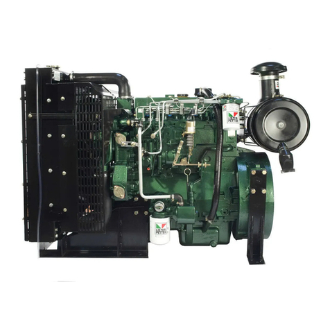
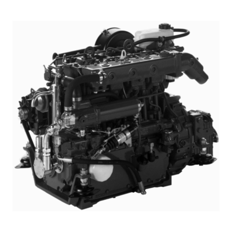
Lister Petter alpha Series Instruction manual

LPW, LPWS & TURBO
ENGINES
WORKSHOP MANUAL
ALPHA SERIES
P027-08240

2
Associated Publications
Master Parts Manual .............................................................................................................. P027-08046
Technical Handbook .................................................................................................................. P027-08247
Operators Handbook .............................................................................................................. P027-08201
Note:
Some information is not yet available and will be included in a later edition.
Associated Publications
Operators Handbooks
LPW, LPWS, LPWT
- English............................................................................................................................. P027-08182
- German ..................................................................................................................... P027-08182/ger
- Italian...........................................................................................................................P027-08182/ita
- French ........................................................................................................................ P027-08182/fre
- Spanish .....................................................................................................................P027-08182/spa
- Portuguese ...................................................................................................................... P027-08196
LPW, LPWS, LPWT
- English............................................................................................................................. P027-08270
- French ........................................................................................................................ P027-08270/fre
- Spanish .....................................................................................................................P027-08270/spa
Master Parts Manuals
LPW/LPWS ............................................................................................................................ P027-08041
LPWS 400 Series ....................................................................................................................P027-08111
Disclaimer
The information, specifications, illustrations,
instructions and statements contained within this
Our policy is one of continued development and
we reserve the right to amend any technical
information with or without prior notice. Whilst
every effort is made to ensure the accuracy of the
particulars contained within this publication neither
the Manufacturer, the Distributor nor the Dealer
shall in any circumstances be held liable for any
inaccuracy or the consequences thereof.
The information given is subject to the Company’s
current Conditions of Tender and Sale, is for the
assistance of users and is based upon results
obtained from tests carried out at the place of
manufacture. The Company does not guarantee that
the same results will be obtained elsewhere under
different conditions.
© Copyright Lister Petter Limited Power Systems
All rights reserved
publication are given with Lister Petter Power
Systems' best intentions and are believed to be
correct at the time of going to press.

3
CONTENTS
Introduction........................................................................................................................... 4
1. General Information.......................................................................................................... 5
2. Engine Servicing and Adjustments................................................................................. 12
3. Engine Fluids.................................................................................................................. 59
4. Operating Instructions ....................................................................................................62
5. Routine Maintenance...................................................................................................... 65
6. Troubleshooting .............................................................................................................. 74
7. Engine Build Details .......................................................................................................77
8. Technical Data................................................................................................................ 80
9. Dismantle and Rebuild ...................................................................................................82
10. Conversion Factors ......................................................................................................84

ALPHA SERIES ENGINES WORKSHOP MANUAL
4
WARNING
Unauthorised adjustments to the emission
compliant fuel injection pump may invalidate
warranty claims. In the USA, unauthorised
adjustment of emission critical components
is prohibited by Federal Law, incurring civil
penalty.
INTRODUCTION
The purpose of this manual is to give information,
operating, maintenance and repair procedures for
the 'Alpha' series of industrial, marine and gas
fuelled engines.
The manual is designed primarily for use by
qualified technicians with electrical and
mechanical experience.
This work can only be carried out if the necessary
hand and service tools are available. When the
user has insufficient tools, experience or ability to
carry out adjustments, maintenance and repairs
then this work should not be attempted.
Where accurate measurements, or torque values,
are required they can only be made using
calibrated instruments.
Under no circumstances should makeshift tools or
equipment be used, as their use may adversely
affect safe working procedures and engine
operation.
The specification details given apply to a range of
engines and not to any one particular engine. In
cases of difficulty the user should consult the local
Lister Petter Power Systems Distributor or Dealer
for further advice and technical assistance.
The information, specifications, illustrations,
instructions and statements contained within this
publication are given with our best intentions and
are believed to be correct at the time of going to
press. Our policy is one of continued development
and we reserve the right to amend any technical
information with or without prior notice.
Whilst every effort is made to ensure the accuracy
of the particulars contained within this publication,
neither the Manufacturer, Distributor or Dealer
shall in any circumstances be held liable for any
inaccuracy or the consequences thereof.
The information given is subject to the Company’s
current Conditions of Tender and Sale, is for the
assistance of users and is based upon results
obtained from tests carried out at the place of
manufacture. This Company does not guarantee
that the same results will be obtained elsewhere
under different conditions.
Parts that have not been approved by the Lister
Petter Power Systems organisation cannot be
relied upon for correct material, dimensions or
finish. This Company cannot therefore, be
responsible for any damage arising from the use of
such parts and the guarantee will be invalidated.
When purchasing parts or giving instructions for
repairs users should, in their own interests, always
specify Genuine Lister Petter Parts and quote the
Description of the Part and the Engine Serial
Number.
Various technical/sales leaflets are available;
please contact your Lister Petter Power Systems
Distributor or Dealer for details.
Training
Comprehensive training in the correct operation,
service and overhaul procedures of engines is
available at the Lister Petter Power Systems
International Product Training Centre.
Please contact Lister Petter Power Systems for
details.
If Problems Occur
If problems occur with your engine, or any of the
Lister Petter approved accessories fitted to it, your
local Lister Petter Power Systems Distributor
should be consulted.
There are Lister Petter Power Systems
Distributors in most countries of the world and
details for these can be obtained from any one of
the companies listed on the back cover or
www.listerpetter.com
Using this Workshop Manual
Each section title is given at the top of the relevant
pages and a full cross reference 'Index' appears at
the back of the manual.
It is recommended the individual steps contained
in the various maintenance or repair operations
are followed in the sequence in which they appear.
At times it may be necessary to refer to other parts
of the section, or to a different section, for more
specific or detailed information.

ALPHA SERIES ENGINES WORKSHOP MANUAL
5
1.1 SAFETY PRECAUTIONS AND
SAFE WORKING PRACTICES
At all times follow the recommended precautions
and safe operating and working practices.
The following are of a general nature and more
specific information appears where it is relevant.
Caution and Warning Symbols
When an engine is operating or being overhauled
there are a number of associated practices which
may lead to personal injury or product damage. The
following are applied throughout this publication.
CAUTION
This caution symbol draws attention to special
instructions or procedures which, if not correctly
followed, may result in damage to, or destruction
of, equipment.
WARNING
This warning symbol draws attention to special
instructions or procedures which, if not strictly
observed, may result in personal injury.
WARNING
A WARNING SYMBOL WITH THIS TYPE OF
TEXT DRAWS ATTENTION TO SPECIAL
INSTRUCTIONS OR PROCEDURES WHICH, IF
NOT STRICTLY OBSERVED, MAY RESULT IN
SEVERE PERSONAL INJURY, OR LOSS OF LIFE.
Follow all Safety Instructions
a. Carefully read all safety messages in this manual
and the safety and informative symbols on your
engine and plant.
b. Starting any diesel engine can be dangerous
in the hands of inexperienced people. Engine
operators must be instructed in the correct
procedures before attempting to start any engine.
c. Do not make any unauthorised modifications as
these may affect the safe operation of the engine
and put the operator at risk.
d. Ensure all starting devices are removed, or
isolated, before commencing any work on the
engine or plant.
Emergency Considerations
a. Be prepared with suitable equipment, and
knowledge, in case a fire starts.
b. Know where to make calls to the emergency
services from.
Handling Fluids Safely
a. When working with fuel or batteries do not smoke
or work near to heaters or other fire hazards.
b. Store flammable liquids away from fire hazards.
c. Do not expose pressurised containers to heat
and do not incinerate or puncture them.
d. Handle fuel with care and always stop the engine
before refuelling. Do not overfill the fuel tank.
e. Thoroughly clean any lubricating or fuel oil from
the skin as soon as possible.
f. Rectify all fuel, coolant and oil leaks as soon
as practicable and clean any spills when they
occur.
g. Remove any build-up of grease, oil or debris.
h. Batteries contain sulphuric acid -if the acid has
been splashed on the skin, eyes or clothes flush
it away with copious amounts of fresh water and
seek medical aid.
Protective Clothing and Equipment
a. Tie long hair close to your head.
b. Do not wear a necktie, scarf, loose clothing
or necklace when working close to a running
engine.
Rotating Machinery
a. Entanglement with any rotating equipment can
cause serious injury or death.
b. If unprotected skin comes into contact with
rotating equipment severe burns can result.
c. It is advisable to remove rings and other jewellery
to prevent possible entanglement in moving
parts. These items could also cause an electric
short circuit if any part of the electrical system is
being worked on.
d. Ensure any lifting equipment to be used has the
correct capacity to lift the engine.
e. Lifting equipment must be designed to give two
verticalliftsfromdirectlyabovetheengineliftingeyes.
f.
g. Do not work under any plant that is only held by
overhead lifting equipment.
Personal Safety
a. Wear close fitting clothing and personal protective
clothing and safety equipment appropriate to the
work being done.
1. GENERAL INFORMATION
The engine lifting eyes fitted to the engine are
suitable for lifting the engine and accessory
assemblies originally fitted by Lister Petter Power
Systems. They must not be used to lift the
complete plant.
c. Ensure a third party knows where you are working
and when you leave the working area.

ALPHA SERIES ENGINES WORKSHOP MANUAL
6
b. Wear suitable ear protection to protect against
objectionable or uncomfortable loud noise.
Prolonged exposure to loud noise can cause
impairment, or loss of hearing.
c. The use of music or radio headphones could
cause a loss of concentration.
Handling Chemical Products Safely
a. Direct exposure to hazardous chemicals can
cause serious injury.
b. Potentially hazardous chemicals include such
items as lubricants, fuel, coolant concentrate,
battery acid, paint and adhesives.
c. Manufacturers Safety Data Sheets will provide
specic details of the physical and health
hazards, safety and emergency procedures and
any necessary personal protection equipment
required while working with hazardous
materials.
Safe Maintenance Considerations
a. Understand the service procedures before
commencing any work.
b. Ensure the work area is clean, dry, well ventilated
and has adequate lighting.
c. Isolate the engine starting system before
commencing any work on the plant.
d. All persons using equipment or processes in
connection with the maintenance of plant and
machinery must have received adequate and
suitable training.
High Pressure Fluids
a. Never allow any part of the body to come
into contact with high pressure hydraulic oil,
compressed air or fuel oil, for example when
testing fuel injection equipment.
b. Both digested and injested uids can lead to
serious injury, possibly with fatal results in a very
short period of time.
Electrical System Considerations
a. Ensure that the battery is of sufcient capacity to
start the engine down to its minimum operating
temperature taking into account any drag that
may be imposed on the engine by the type of
transmission that is attached to it.
b. Ensure the battery and all engine wiring cables
are of sufcient size to carry the currents
required.
c. Check that the engine mounted alternator is of
sufcient output to cope with the total electrical
load required by the machine to which it is tted.
d. Ensure engine wiring cables are:-
Bound together in a loom and adequately
supported.
Routed to avoid any hot surfaces, particularly the
exhaust system.
Not in contact with any sharp corners or rough
surfaces so as to avoid any possibility of chafng
taking place.
Alternator Precautions
a. Never remove any electrical cable without rst
disconnecting the battery.
b. Only disconnect the battery with the engine
stopped and all switches in the OFF position.
c. Ensure cables are tted to their correct terminals.
A short circuit or reversal of polarity will ruin
diodes and transistors. Never connect a battery
into the system without checking that the voltage
and polarity are correct.
d. Never ash any connection to check the current
ow or experiment with any adjustments or
repairs to the system.
e. The battery and alternator must be disconnected
before commencing any electric welding when a
pole strap is directly or indirectly connected to the
engine.
Starter Battery Precautions
WARNING
Sulphuric acid in battery electrolyte is poisonous,
is strong enough to burn skin, eat holes in
clothing and cause blindness if splashed into
the eyes.
a. Do not smoke near the batteries and keep sparks
and ames away from them.
b. Batteries contain sulphuric acid - if the acid has
been splashed on the skin, eyes or clothes ush
it away with copious amounts of fresh water and
seek immediate medical aid.
c. Keep the top of the battery well ventilated during
charging. Switch off the battery charger before
connecting or disconnecting the charger leads.
d. Disconnect the battery negative (earth) lead rst
and reconnect last.
e. Never 'ash' connections to check current ow.
f. A damaged or unserviceable battery must never
be used.
g. Do not attempt to charge a frozen battery; it may
explode; warm the battery to 16°C (60°F).
Waste Contamination
a. Extreme care must be taken to ensure that waste
oil, fuel, lter elements, coolant concentrate,
battery electrolyte, solvents or other toxic

ALPHA SERIES ENGINES WORKSHOP MANUAL
7
1.2 SAFETY SYMBOLS
This section identifies the ISO 8999 symbols currently used by Lister Petter Power Systems
wastes are disposed of in accordance with local
regulations to prevent contamination.
b. Drains and water courses must not be used to
dispose of contaminated, or waste fluids.
Fuel System Precautions
a. When priming or checking the fuel injection
pump timing, care must be taken to wipe spilled
fuel from the outside of the engine.
b. Always fit a new joint when a union has been
disturbed.
c. Special care must be taken to see that there
is no leakage from the joints of the fuel pipe
connection to the pump.
d. When tightening or loosening the fuel injection
pump delivery connections, use two spanners to
prevent the unsealing of the fuel pump delivery
valve holders.
e. When refitting the fuel pipe from the pump to
injector, the connection to the injector must be
tightened before the connection to the fuel pump.
This procedure will ensure that there is no
leakage from these joints.
f. It is most important that all fuel joints are tight and
leak proof.
g. Always fill the fuel tank through a fine strainer,
preferably at the end of the engine work period.
If any sediment is stirred up during the process
this has time to settle before the engine is used
again, this will minimise the risk of condensation
contaminating the fuel.
Ifcansareused,avoidtippingoutthelastfewdrops.
h. Funnels are very difficult to keep clean in dusty
conditions.
Wash them before and after use and wrap them up
when not required, or fill the tank direct from a
small mouthed screw capped fuel can.
i. The fuel injection equipment is manufactured to
very accurate limits and the smallest particle of
dirt will destroy its efficiency.
Fuel free from water and contaminants is of the
utmost importance.
Precautions for Oil, Filters and Elements
a. Used liquid filters and elements contain some
of the filtered liquid and should be handled and
disposed of with care.
b. After handling new or used elements the users
hands should be thoroughly washed, particularly
before eating.
c. Fuel and new or used lubricating oil may cause
skin irritation.
Contact with used lubricating oil can cause cancer,
birth defects or other reproductive harm.
d. The materials used in the manufacture and
treatment of some filters and elements may
cause irritation or discomfort if they come into
contact with the eyes or mouth and they may
give off toxic gasses if they are burnt.
e. Extreme care must be taken to ensure that
waste oil, filter elements, solvents or other toxic
wastes are disposed of in accordance with local
regulations to prevent contamination.
f. As a direct result of combustion the lubricating
oil may contain harmful acids and therefore
it should not be left in the sump if it is known
that the engine will not be used for extended
periods.

ALPHA SERIES ENGINES WORKSHOP MANUAL
8
LPWT4
Fuel Lift Pump
Lifting Eye Turbocharger
Fuel Filter
Radiator
Fan
Oil Cooler
Oil Filter
Water Pump/Thermostat housing
1.3 ENGINE FEATURES
LPW2
Inlet Manifold Exhaust Manifold
Fuel Filter
Oil Filter
Oil Filler
Engine 'Stop' Control
Radiator Fan
Flywheel Housing

ALPHA SERIES ENGINES WORKSHOP MANUAL
9
1.4 ENGINE IDENTIFICATION
1.4.1 Nomenclature
LPW2, 3 and 4 - two, three and four cylinder, direct
injection, naturally aspirated water cooled diesel
engines.
LPWT4 - four cylinder, direct injection, turbocharged
water cooled diesel engine.
LPWS2, 3 and 4 - two, three and four cylinder,
indirect injection, naturally aspirated water cooled
diesel engines.
LPWST4 - four cylinder, indirect injection,
turbocharged water cooled diesel engine.
1.4.2 Build Information
The engines within each range have been
assembled to predetermined configurations and
where the build number is preceded by a '9' this
indicates that the engine is either of a non-standard
configuration, or contains non-standard parts or
accessories.
When new parts are required for such a build it is
suggested that reference be made to Lister Petter
Power Systems to determine the exact engine
specification and which parts are non-standard.
Where the engine serial number contains a 'G', for
example GLPW3, this denotes the engine was built
into a generating set by Lister Petter Power Systems.
A full list of builds is given in "7. Engine Build
Details".
1.4.3 Engine Serial Number
The engine serial number is stamped on a plate
attached to the engine.
It is necessary to identify the type and build of
each engine to enable the correct maintenance
procedures, as described later in this publication,
to be carried out.
An example number is shown below:
06 00123 LPW3 A 01
06 ............. Year of manufacture code (06 = 2006)
00123 ................... Consecutive number of engine
LPW3 .............................. Model (T = turbocharger,
S = indirect injection, G = gas fuelled)
A ....................................... Anti clockwise rotation
01 ................................................... Build of engine

ALPHA SERIES ENGINES WORKSHOP MANUAL
10
1.5 BATTERY DETAILS
WARNING
Battery posts, terminals and related accessories
contain lead and lead compounds, chemicals
known to the State of California to cause cancer
and reproductive harm. Wash hands after
handling.
WARNING
Sulphuric acid in battery electrolyte is poisonous,
is strong enough to burn skin, eat holes in
clothing and cause blindness if splashed into
the eyes.
1.5.1 Battery Polarity
The electrical system for all engines is 12 or 24 volt
negative earth (check with meter).
1.5.2 Recommended Battery Type
Heavy Duty Batteries to BS3911:982 or IEC95-1
are recommended for all engine applications.
Fortemperatures below -18°C (0°F), highdischarge,
low resistance Arctic or Alkaline batteries must be
used.
Lister Petter Power Systems recommend that a
battery shouldprovide a minimum cranking period
of 60 seconds from a 70% charged 12 volt battery,
with a minimum voltage at the end of the cranking
period of 8.4 volts (16.8 volts on a 24 volt system).
Note:
Tropical climates apply to those countries or
areas where the average temperature of any
month of the year exceeds 27°C (80°F).
1.5.3 Connecting Batteries
It is most important to ensure that the starter
battery, or batteries, are properly connected and all
connections are tight.
Figure 1.5.3 Battery Connections
A - 12 volt system using four 6 volt batteries connected in series-
parallel.
B - 12 volt system using two 6 volt batteries connected in series.
1.5.4 Connecting a Slave Battery
A slave, or booster battery can be connected in
parallel with the existing battery to aid starting in
cold weather conditions.
WARNING
Heavy duty jumper leads must always be
used and no attempt must be made to use any
others.
WARNING
Do not allow the jumper lead free ends to directly,
or indirectly touch the engine at any time.
1. Connect one end of the jumper lead to the
positive (+) post of the slave battery.
2. Connect the other end of the jumper lead to the
positive (+) post of the battery connected to the
starter motor.
3. Connect one end of the jumper lead to the
negative (-) post of the slave battery.
4. Make the final connection of the negative (-)
cable to a good earth on the engine frame and
away from all the batteries.
1.5.5 Disconnecting a Slave Battery
1. Start the engine.
2. Disconnect the slave battery negative (-) jumper
lead first.
3. Disconnect the remaining jumper leads.
1.5.6 Cold Cranking Battery Requirement
The cold cranking battery requirement table below
is to BS3911 and IEC95-1.
The table below defines the recommended minimum
cold cranking performance required from lead acid
batteries, when tested at an ambient temperature
of -18°C (0°F).
Therecommendationsmadeassumethattheengine
is filled with the recommended type and grade of
lubricating oil and is not required to start against
high inertia loads such as concrete mixers, tar
boilers, hydraulic pumps, screw pumps and similar.
In these applications, wherever possible, means
should be provided to overcome such loads by the
inclusion of clutches and unloading valves, etc.

ALPHA SERIES ENGINES WORKSHOP MANUAL
11
1.5.7 Recommended Battery Type
Heavy Duty Batteries to BS3911:982 or IEC95-1
are recommended for all applications.
Fortemperatures below -18°C (0°F), highdischarge,
low resistance Arctic or Alkaline batteries must be
used.
System Volts
Ambient Temperature Range °C (°F)
Above 27° (80°) 26° to 1°
(79° to 34°)
0° to -8°
(32° to -18°)
-9° to -18°
(16° to 0°)
LPW2, LPWS2 12V 115A 150A 210A 350A
24V 75A 90A 140A 215A
LPW3, LPWS3 12V 175A 225A 345A 600A
24V 90A 105A 160A 285A
LPW4, LPWT4, LPWS4, LPWST4 12V 190A 255A 380A 670A
24V 75A 105A 160A 300A
Ambient Temperature Range °C (°F)
30° to 5°
(86° to 41°)
4° to -15°
(39° to 5°)
-16° to -25° (3°
to -13°)
-26° to -32°
(-15° to -26°)
Below -32°
(-26°)
LPW, LPWS A-D B-D-F C-D-I C-D-I-G C-D-I-G-H
LPWT4 B-D-F-I
1.15.7.1 Table Code
A. 15W/40 Lubricating oil in the sump.
B. 10W/30 Lubricating oil in the sump.
C. 5W/20 Lubricating oil in the sump.
D. 12 volt starting.
E. Air inlet manifold heater energised while cranking.
F. High discharge, low resistance artic type or alkaline batteries.
G. Heating of the engine and batteries in a housing or engine room.
H. Air inlet manifold heater energised for preheat and while cranking.
1.5.8 Cold Starting Performance
The figures given in the table below are for bare
engines only.
Lister Petter Power Systems recommend that a
battery shouldprovide a minimum cranking period
of 60 seconds from a 70% charged 12 volt battery,
with a minimum voltage at the end of the cranking
period of 8.4 volts (16.8 volts on a 24 volt system).

ALPHA SERIES ENGINES WORKSHOP MANUAL
12
2.1 PRELIMINARY INSTRUCTIONS
WARNING
Maintenance must be performed by qualied
persons who are conversant with the hazards
of fuels, electricity and machinery.
Before commencing any work on the engine read
the "Safety Precautions and Safe Working Practices"
at the front of this manual.
Dismantling and Rebuilding
When the engine is being dismantled all items must
be identied and retained in their respective cylinder
orientation and all related components must be
treated similarly.
The instructions given deal with individual
components and it may be necessary to remove
others before the relevant instructions can be
carried out.
a. Disconnect or isolate any non-electric starting
systems.
b. Disconnect and remove the battery.
c. Drain the diesel fuel and lubricating oil.
d. Drain the coolant.
e. Disconnect all services.
f. Remove any accessories or components that
may be susceptible to damage when the engine
is turned out of its normal plane.
WARNING
Do not attempt to remove the fuel injection pumps
without referring to the relevant instructions.
WARNING
These engines are tted with hydraulic tappets
therefore it is important to follow the procedures
given.
Because of the various engine congurations, and
installations in which the engine can be tted, it is not
possible to give detailed instruction for each one.
Tightening torques are included in the text as
necessary and in table format in "05.5 Spanner
Torques".
When assembling the engine, use the same type
of lubricating oil as used in the engine to spray all
moving parts during assembly. All bearings and
bushes must be well lubricated during assembly.
Renew all joints, gaskets, connecting rod nuts and
bolts and the cylinder head bolts.
2.2 THE AIR CLEANER
Plastic air cleaners have been available since
March 2000 and these complement the existing
sheet metal types.
Every effort should be taken to ensure that the air
cleaner draws in combustion air at the prevailing
ambient temperature. Any increase in combustion
air temperature above the standard engine
reference condition of 25°C (77°F) will incur an
engine derate factor.
2.2.1 The Light Duty Air Cleaner
The industrial type has a replaceable paper
element, and the marine type a serviceable foam
element.
The snout is normally tted lying horizontal and
pointing towards the gear end although the cleaner
itself can be rotated through 360°.
1. Release the three cover clips (A).
2. Lift off the cover (B).
3. Lift out the element (C).
4. Industrial Engines:
a. Fit a new paper element.
Figure 2.2.1 Light Duty Air Cleaner
2.2.2 The Cyclonic Air Cleaner
A cyclonic air cleaner can be remote or engine
mounted over the ywheel housing, both are
connected to the engine by a moulded rubber hose
secured by jubilee clips.
Regularly remove the dust cap (A) and empty all
the dust
2. ENGINE SERVICING AND ADJUSTMENTS

ALPHA SERIES ENGINES WORKSHOP MANUAL
13
Figure 2.2.2 Cyclonic Type Air Cleaner
1. Access to the paper element (B) is gained by
undoing the wing nut in the centre of the main
body of the lter.
2. Remove the element.
3. The element can be cleaned by directing a low
pressure compressed air nozzle up and down
the pleats from inside the element.
4. Inspect the element for damage by placing a
suitable light source inside it. If the element is
found to have any holes it must be replaced.
5. Replace the element and dust cap.
2.2.3 Intake Restriction
The maximum intake restriction gures at full load
are 254mm WG (10.0in WG).
2.3 THE MANIFOLDS AND SILENCER
Various inlet and exhaust manifolds are available for
industrial and marine engines for which full details
can be found in the relevant Master Parts Manual.
The inlet manifold is secured by bolts and the exhaust
by studs. There are two studs or bolts to each cylinder
and these must be torqued to 9.0Nm (6.5lbf ft).
Exhaust manifold bolts on turbocharged engines
LPW(S)T4 must be torqued to 21Nm (15.5lbf-ft).
Whenever the manifolds are replaced all traces of
the old exhaust gaskets and joints must be removed
and new ones tted.
WARNING
EXHAUST GASSES CONTAIN CARBON
MONOXIDE WHICH IS A COLOURLESS,
ODOURLESS AND POISONOUS GAS THAT
CAN CAUSE UNCONSCIOUSNESS AND
DEATH.
2.3.1 The Inlet Manifold Restrictor
Some builds, as shown in the table below, are tted
with an inlet manifold restrictor.
The restrictor is secured in position with Hylosil 303.
Builds
LPW2 18, 27, 28, 41, 57, 58, 74, 79, 81, 177
LPW3 18, 27, 28, 41, 74, 79, 81, 113, 177
LPW4 18, 27, 28, 41, 57, 74, 79, 81
LPWS2 18, all 400 Series
LPWS3 07, 18, 41, 57, all 400 Series
LPWS4 18, 57, all 400 Series
2.3.2 The Exhaust Silencer
Various silencers and adaptors are available for
industrial and marine engines for which full details
can be found in the relevant Master Parts Manual.
CAUTION
Detrimental damage to the engine, or loss of
performance, may be caused if exhaust gasses
are sucked in by the air cleaner, the axial or
radiator fan.
2.3.3 Exhaust Back Pressure
The maximum permissible back pressure gures
are 762mm WG (30.0in WG) except the LPW(S)T4
which are 508mm WG (20.0in WG).
2.4 THE COLD START AID
Cold start aids are not tted to LPWG engines.
2.4.1 LPW and LPWT
To provide additional heating of the combustion air
during starting a 345W heater plug may be tted to
the inlet manifold on LPW engines. A 696W plug is
tted on LPWT4 engines as standard.
Figure 2.4.1 Manifold Heater Plug
2.4.2 LPWS
LPWS engines are tted with a 12V glow plug
for each cylinder and a manifold heater plug as
standard.

ALPHA SERIES ENGINES WORKSHOP MANUAL
14
Figure 2.4.2 Glow Plug Locations
A - LPW and LPWST4 400 Series Builds
B - All Other 300 Series Builds
On all LPWS engines, other than 400 series builds,
the plugs are tted into the side of the cylinder head
as shown at 'B' in Figure 2.4.2.
On all 400 series builds, the plugs are tted into the
top of the cylinder head between the injector and
cylinder head cover, as shown at 'A' in Figure 2.4.2.
Fitting Glow Plugs to 400 Series Builds
1. Fit the glow plug (B) into the adaptor (A) and
torque it to 15.0Nm (11.0lbfft).
Figure 2.4.3 Glow Plug - 400 Series Builds
2. Screw the plug and adaptor assembly into the
cylinder head and torque it to 27.0Nm (20.0lbf ft).
3. Fit the electrical feed cable.
2.5THETURBOCHARGER-LPW(S)T4
The turbocharger bearing is fed by a pressurised
oil feed from the crankcase oil gallery to the top of
the turbocharger.
A non-pressurised return to the crankcase door
allows the oil to drain back to the sump.
CAUTION
Serious damage to the turbocharger bearing can
result if or any reason the turbocharger housing
is not full of oil.
It is recommended that these engines run on 'no
load' after starting for 30 seconds, to ensure an
adequate oil supply to the turbocharger, and 30
seconds before stopping to allow the heat from the
bearing to dissipate.
2.5.1 Removing the Turbocharger
1. Disconnect and remove the turbocharger oil feed
pipe (A) and oil return pipe (B).
2. Remove the air cleaner, exhaust silencer and
associated parts.
3. Support the turbocharger and remove the three
mounting stud nuts (C).
4. The turbocharger can be dismantled by removing
the four nut (D).
Note:
If the turbo is dismantled it must be sent back
to Garrett to be balanced.
Figure 2.5.1 The Turbocharger
2.5.2 Retting the Turbocharger
1. If the turbocharger was dismantled t a new joint
(E) and assemble the unit.
It may be an advantage to replace the three nuts
and studs to aid removal at a later date.
2. Fit a new joint (F) and replace the oil feed and
return pipes.
3. Before attempting to start the engine for the rst
time read the 'Caution' in "2.5 The Turbocharger
- LPW(S)T4".
2.6 THE CRANKCASE BREATHER
The breather canister and hoses should be checked
periodically, and cleaned if there is evidence of
frothy, emulsied oil blocking the passageways.
This should be done at least every 500 hours; more
often in cold climates, or if the engine is started and
stopped frequently without being allowed to reach
normal operating temperature.
Blow-by vapours are routed to the canister through
a hose connected to the cylinder head cover. Any
entrained lubricating oil mist is separated in the
canister and allowed to drain back to the sump

ALPHA SERIES ENGINES WORKSHOP MANUAL
15
2.7.3 Starter Motor Terminal Torques
Starter Motor Battery +
Terminal 1
Link
Terminal 2
Lucas/Magnetti Marrelli
(discontinued)
4.0-4.2 3.1-3.2
2.95-3.01 2.3-2.4
Denso Starter 5.89-11.77 5.89-11.77
4.34-8.68 4.34-8.68
UniPoint Starter 5.89-11.77 5.89-11.77
4.34-8.68 4.34-8.68
Figure 2.7.3 Starter Motor Terminals
A - Lucas
B - Denso and UniPoint
2.8 THE ALTERNATOR
From March 1999 a Mitsubishi 50 amp alternator
has been tted which replaced the Magnetti Marelli
(Lucas) type. The alternator accessory kit codes
remain the same but new parts and wiring looms
have been introduced.
through a tting on the crankcase door.
The remaining vapours are then routed from the
canister to the air inlet. This results in the blow-
by vapours being re-burned in the combustion
chamber, thus preventing their escape to the
atmosphere.
A small amount of oil may collect in the transition
sleeve and; this is normal.
2.6.1 LPWT4 and LPWST4 Engines
The combined oil separator and crankcase breather
is tted above the ywheel housing and attached
to the air inlet and No.4 cylinder head cover on
industrial engines, No.2 on marine engines, by
exible pipes.
A restrictor (A) is tted in the outlet hose on some
builds and It is important to ensure it is replaced
and pushed into the centre of the outlet hose.
Figure 2.6.1 LPWT4 Oil Separator and Breather
The combined oil separator and breather is the
same as that tted to the LPW(S)T4. It is tted
above the ywheel housing and attached to the air
inlet and the ywheel end cylinder head cover.
2.7 THE STARTER MOTOR
Figure 2.7.1 Starter Motors
A - Lucas (discontinued)
B - Denso and UniPoint
2.7.1 Removing the Starter Motor
1. Isolate the battery.
2. Disconnect the electrical wiring loom from the
starter.
3. Support the starter motor and remove the
mounting bolts.
On 24 volt starter motors (approved applications
only) the bolts pass through the starter and screw
into the ywheel housing.
2.7.2 Replacing the Starter Motor
1. Isolate the battery.
2. Support the starter motor and t the mounting
bolts nger tight.
3. Torque the bolts to 41.0Nm (30.0lbf ft).
4. Replace the cable loom connections in the
positions as shown in 'Figure 2.7.3'.
5. Torque the connections to the values given in
"2.7.3 Starter Motor Terminal Torques".

ALPHA SERIES ENGINES WORKSHOP MANUAL
16
If an alternator is not required, a jockey pulley is
tted in its place.
The alternator is belt driven at the gear cover end
by a V-ribbed belt and the alternator to engine
speed ratio and output is constant for all engines.
An additional 100A earth return, or 55A insulated
return, alternator to power on board equipment is
available as an option for some marine builds.
Industrial - 12 volt negative earth with an engine
mounted 45A or 50A battery charging alternator.
CAUTION
When running the engine for battery charging
purposes the engine speed should be set to a
minimum of 1200r/min.
2.8.1 Terminal Identication
Terminal Mitsubishi Magnetti Marelli
Battery + B +
Warning light L IND
Phase tape P W
Regulator
reference R not available
WARNING
The Mitsubishi 'R' terminal is for the alternator
reference circuit and must be wired into the
circuit.
2.8.2 Removing the Alternator
These instructions are specic to a Marelli Magnetti
alternator but also apply in general to the Mitsubishi
type.
1. Isolate the battery.
2. Remove the cable loom plug from the alternator
3. Slacken the alternator lower pivot bolt and nut (A).
4. Slacken the two adjuster arm retaining bolts (B).
5. Place the palm of the hand under the alternator
and lift it upwards until the alternator moves
towards the crankcase sufciently to remove the
drive belt.
6. Support the alternator and remove the bolt from
the slotted section of the adjusting arm.
7. Support the alternator and remove the lower
pivot bolt and nut.
8. Lift the alternator clear.
Figure 2.8.2 Magnetti Marelli Alternator Adjustment Arm LPW/LPWS
2.8.3 Replacing the Alternator
1. Hold the alternator in position and replace the
lower pivot bolt and nut.
2. Replace the alternator adjusting arm bolts nger
tight.
3. Ensure the adjusting arm is tted with the offset
the correct way round for the type of engine as
shown in 'Figure 2.8.1'
4. Place the palm of the hand under the alternator
and lift it upwards until the alternator moves
towards the crankcase sufciently to replace the
drive belt by hand.
5. Move the alternator outwards as far as possible
by hand and tighten the pivot and adjusting arm
bolts.
2.9 THE DRIVE BELT
It is important that the tension of the drive belt is
checked after the rst 50 hours, after an overhaul,
after a new belt has been tted and as specied in
"5.3 Routine Maintenance - Schedule Hours".
The belt is manufactured from specic materials
and construction. No other belt than that specied
must be used.
The crankshaft and driven pulleys must have a
smooth nish to the grooves, and be aligned within
1.6mm (0.061in), measured at the centre of the
grooves.
CAUTION
The belt must be slackened and tted to the
pulleys by hand, under no circumstances must
it be levered or wound on. The belt must be
replaced every 2000 hours, irrespective of its
condition.

ALPHA SERIES ENGINES WORKSHOP MANUAL
17
2.9.1 Tensioning the Drive Belt
When a new belt is correctly tted and tensioned
a force (F) of 31.0-33.5N (7.0-7.5lbf) is required to
deect it a distance (d) of 3.5mm (0.14in).
On subsequent checking and adjustment a force (F)
of 22.0-24.0N (5.0-5.4lbf) is required to deect it a
distance (d) of 3.5mm (0.14in).
Figure 2.9.1 Checking Belt Tension
LPW, LPWS, LPW
CAUTION
To ensure the correct measurement is obtained
the tensioning measurement must only be taken
on the longest length between pulley centres.
2.9.2 Drive Belt Tension Value
Belt Tension Force (F)
N lbf
New Belt 31.0-33.0 7.0-7.5
Used Belt 22.0-24.0 5.0-5.4
2.10 THE FUEL TANK
A 12.0 litre (2.5 gal; 3.0 US gal) polypropylene
tank, with a screw-on ller cap is available as an
optional accessory. The tank is secured by two
nylon webbing straps tensioned at the base.
.
Figure 2.10.1 The Fuel Tank
2.10.1 Removing the Fuel Tank
1. Drain the fuel tank into a clean receptacle.
2. Either, remove the fuel pipe at the lter inlet
or, use a pair of pliers to squeeze the tails of
the fuel pipe clip at the tank outlet end together
sufciently. Move the clip sideways along the
pipe and pull the pipe off.
3. Disconnect the leak-off pipe from the back of the
tank.
4. Slacken, or remove, the two setscrews securing
the straps to the mounting bracket base.
5. Remove the tank.
2.10.2 Maintenance of the Fuel Tank
Remove any sediment from the tank and, if
necessary, ush the tank with clean kerosene and
allow it to drain.
2.10.3 Replacing the Fuel Tank
1. Support the tank and replace it on the mounting
bracket.
2. Replace the two setscrews securing the straps
and tighten them until the tank is secured.
3. Replace the fuel pipe to either the lter or fuel
tank.
4. Push the leak-off pipe onto the tank.
5. Rell the fuel tank.
2.11 THE FUEL LIFT PUMP
A fuel lift pump is tted to all engines, except Builds
71 and 72, and is operated from the camshaft by
a push rod.
The pump has a maximum lift of approximately 3m
(10ft) and a maximum head of 600mm (2ft).
Note:
It is recommended that the fuel lift pump
diaphragm is inspected at frequent intervals
if it is known the fuel is contaminated. It
should also be inspected at regular intervals
on engines in low duty cycle applications; for
example, stand-by generating sets.
On engines not tted with a lift pump a blanking
plate is tted. The plate is secured by two nuts
torqued to 13.5Nm (10.0lbf ft). A lift pump push rod
will not be tted.
The current industrial Pienne and Corona types of
lift pump are not interchangeable with the earlier
AC Delco pump or the marine type. Full details can
be found in the relevant Master Parts Manual.

ALPHA SERIES ENGINES WORKSHOP MANUAL
18
Figure 2.11.1 Industrial Fuel Lift Pumps - Pienne/Corona pump
2.11.1 Replacing the Fuel Lift Pump
The fuel lift pump is operated by a push rod from
the camshaft and the distance from the camshaft
to the pump tappet is not adjustable.
Care must be taken to ensure that only one paper
joint is tted between the pump and crankcase.
Current pumps are tted with plain and spring
washers under the mounting stud nuts. It is
recommended that plain washers are tted to
earlier pumps if this has not yet been done.
1. Remove the fuel inlet and outlet pipes from the
pump.
2. Remove the two stud nuts, spring washers and
plain washers.
3. Lift off the pump.
4. Remove all traces of the old joint.
5. If a new push rod is being tted, grease it with
Shell Alvania 2 prior to assembly.
6. Ensure the pump and crankcase mating surfaces
are clean and dry before tting a new paper
joint.
7. Ret the pump, plain and spring washers and
nuts. Torque the two nuts to 21.0Nm (15.5lbf ft).
8. Replace the inlet and outlet fuel pipes.
2.12 FILTER AND AGGLOMERATOR
The fuel lter is an essential part of the engine and
it must never be run without a lter. The element
should be renewed every 500 hours, or more
frequently if for any reason the fuel is known to be
dirty.
2.12.1 Changing the Fuel Filter Element
The element should be renewed every 500 hours,
or more frequently if for any reason the fuel is
known to be dirty.
1. Isolate the fuel supply or drain the tank.
2. Unscrew the centre bolt (A) of the lter
assembly.
3. Discard the old element (B) and sealing rings (C).
4. Fit a replacement element with new sealing rings.
Figure 2.12.1 Fuel Filter
5. Fill the fuel tank and prime the system.
6. Run the engine and check to see that no fuel is
leaking from the lter.
2.12.2 Priming the Fuel System
1. Ensure there is sufcient fuel.
2. Release the bleed screws (A) on the lter and re-
tighten when no further air bubbles are expelled.
Figure 2.12.2 Priming the Fuel Filter
3. On variable speed engines, move the speed
control to the fast position
4. Move the engine stop/run control from the stop,
to the run position.
5. Operate the fuel lift pump by hand.
6. Tighten (A) after all air bubbles are expelled.
2.13 THE FUEL INJECTION PUMP
The individual fuel pumps are located at the side of
the engine, between the push rods. They are secured
to the top of the crankcase by a clamp and nut.
Each fuel pump is timed individually, using the
appropriate ywheel timing degree mark. When
an existing or new fuel pump is retted, it is only
necessary to ret the existing shim pack, or a new
pack of the same thickness as the original.
Fuel pump part numbers for the various engine
builds are given in '2.13.6 Fuel Pump Part Numbers'.

ALPHA SERIES ENGINES WORKSHOP MANUAL
19
2.13.1 Removing a Fuel Pump
To retain the governor setting leave one fuel pump
in position.
1. Isolate the fuel supply.
2. Using a pair of pliers, squeeze the tails of
the exible fuel pipe clip (A) at the pump end
together sufciently to enable the clip to be
moved sideways along the pipe.
Figure 2.13.1 Fuel Pump
3. Pull the pipe off of the fuel pump.
4. Turn the engine control anti clockwise to the stop
position.
5. Remove the fuel pump clamp (B).
6. Lift out the fuel pump.
CAUTION
If more than one fuel pump is being removed
extreme care must be taken to ensure that the
shim pack is kept with the relevant pump and
cylinder.
WARNING
Under no circumstances must any attempt be
made to remove the fuel pump tappet stud from
the crankcase. The shims tted between the
steel plate and the fuel pump ange must not
be removed or added to.
2.13.2 Servicing the Fuel Pump
No attempt to dismantle the fuel pump, other than
to replace the delivery valve, must be made.
Whenever the delivery valve holder is removed a
new joint must be tted before it is reassembled and
the holder torqued to 47.0Nm (35.0lbf ft).
2.13.3 Retting a Fuel Pump
Before retting a fuel pump, the governor must be
correctly adjusted. If it has been removed or is known
to be out of adjustment, refer to "2.53 Setting the
Governor".
If the fuel pump tappet has been removed it must
be replaced with the longer slot (A) facing outwards.
This will ensure it is correctly located over the end of
stud (B) which is tted inside the crankcase.
Figure 2.13.3 Fuel Pump Tappet and Stud
The tappet can be placed into the crankcase with
the aid of long-nosed pliers held open against the
top inside edge of the tappet recess.
1. Hold the engine control in the stop position.
2. Press down on the top of the fuel pump tappet,
and slowly turn the crankshaft until the fuel pump
tappet is felt to be at its lowest position.
3. Using the fuel pump rack setting gauge, 317-
50114, clamp the pump rack (C) with the end
protruding 55.5mm (2.18in) from the crankcase
end face (D).
Figure 2.13.3 Setting the Rack - 317 -50114 - Lister Service Tool
4. Replace the correct original shim pack to the fuel
pump.
5. Gently insert the fuel pump, and shims into the
crankcase taking care to ensure that the fuel pump
rack engages with the slot in the governor rack.
6. Carefully turn the fuel pump anti clockwise until
the pump rack is felt against the stop.
Hold the pump in this position, and replace the fuel
pump clamp with the bevelled face of the nut towards
the clamp nger tight. Take care to ensure the pump
does not move.
CAUTION
It is possible that the engine will not stop when
required if the pump is not turned anti clockwise
before tightening down or it moves before, or
while, being tightened.

ALPHA SERIES ENGINES WORKSHOP MANUAL
20
7. Torque the nut to 34.0Nm (25.0lbf ft).
8. Replace the fuel pipes.
9. To ensure the control lever is positively stopped by
the control lever stop screw and not the fuel pump
stops refer to "2.55 Setting the Stop/Run Lever".
2.13.4 Fuel Pump Shims
The shims tted by the pump manufacturer between
the pump ange and the steel plate must not be
removed or added to.
2.13.5 Fuel Pump Shim Packs
Extreme care must be taken to ensure that the
individual shim packs that are tted between each
fuel pump plate and the crankcase are retained with
their original respective cylinder.
The colour coded shims are available in three
sizes:
Green 0.075mm (0.003in).
Slate blue or white 0.125mm (0.005in).
Black 0.250mm (0.010in).
2.14 FUEL PUMP TIMING
It will only be necessary to carry out pump timing
if the original shims have been lost or mixed with
those of another pump.
The following shim combinations are used to vary
the timing.
Change Shim Combination
1º 1 Green
2º 1 Green and 1 slate blue or white
3º 1 Green and 1 black
4º 2 Green and 1 black
To advance the timing - remove shims.
To retard the timing - add shims.
2.14.1 Piston Displacement Method
The following sequence of operations must be
repeated for each pump as necessary, using the
appropriate ring degree mark on the ywheel.
1. Rotate the piston to TDC on the ring stroke.
2. Use a suitable probe resting on top of the piston, on
the gudgeon pin axis, to accurately determine TDC.
3. Rotate the ywheel clockwise to beyond the
specied piston displacement, as given in "2.15
Fuel Pump Timing Values", from TDC.
The correct gure for the type and build of engine
must be used.
4. Carefully rotate the ywheel anti clockwise until
the correct piston displacement gure is reached.
5. Use a probe to measure dimension ‘X’ which is
from the top face of the crankcase, to the top of
the fuel pump tappet cap.
6. Subtract dimension ‘X’ from dimension ‘B’ to give
the required thickness of shim pack to be tted
between the fuel pump plate and the crankcase.
Figure 2.14.1 Fuel Pump Timing Dimension
B = 51.2mm (2.012in) at port closure
2.14.2 Timing Gauge Method
1. Assemble the pipe (A) to the gauge ensuring that
the pipe nuts are tight.
2. Remove the fuel pipe from the pump to the injector.
3. Connect the gauge and pipe to the fuel pump
delivery union for the cylinder being time.
Figure 2.14.2 Fuel Pump Timing Gauge - 317-50518 -
Lister Petter Service Tool
4. Bleed the fuel lter and pump.
5. Ensure the fuel pump rack is in the run position.
6. Turn the ywheel in the direction of rotation to
prime the gauge.
7. Turn the ywheel until the relevant timing gure
is visible on the compression stroke.
8. Turn the ywheel against rotation for 50mm (2.0in).
9. Slowly release the gauge knob (B) until the fuel
level is in line with the calibration mark on the
gauge sight glass.
10. Turn the engine in the direction of rotation
extremely slowly, until the fuel in the sight glass
just moves.
11. Check that the correct ywheel timing gure, as
given in "2.15 Fuel Pump Timing Values", is visible.
12. Remove the gauge and replace the pump to
injector pipe.
Other manuals for alpha Series
4
This manual suits for next models
11
Table of contents
Other Lister Petter Engine manuals

Lister Petter
Lister Petter ALPHA Series User manual

Lister Petter
Lister Petter TS1 Instruction manual

Lister Petter
Lister Petter ALPHA LPW2 Service manual

Lister Petter
Lister Petter alpha Series Service manual

Lister Petter
Lister Petter GW3 Service manual

Lister Petter
Lister Petter TS1 Instruction manual

Lister Petter
Lister Petter alpha Series Service manual

Lister Petter
Lister Petter L Series Service manual

Lister Petter
Lister Petter T Series Service manual

Lister Petter
Lister Petter T Series Service manual