Lister Petter L Series Service manual

Lister Petter LT and LV Operators Handbook page 1
THE 'L' SERIES
OPERATORS HANDBOOK
H
ANDBOOK
C
ONTENTS
page
Issue 10: April 2003
Introduction ...........................................................................................2
Engine Features....................................................................................3
1. General Information ..........................................................................4
2. Operating Instructions.......................................................................7
3. Engine Fluids ..................................................................................11
4. Engine Servicing .............................................................................13
5. Index ...............................................................................................23

Lister Petter LT and LV Operators Handbookpage 2
Introduction
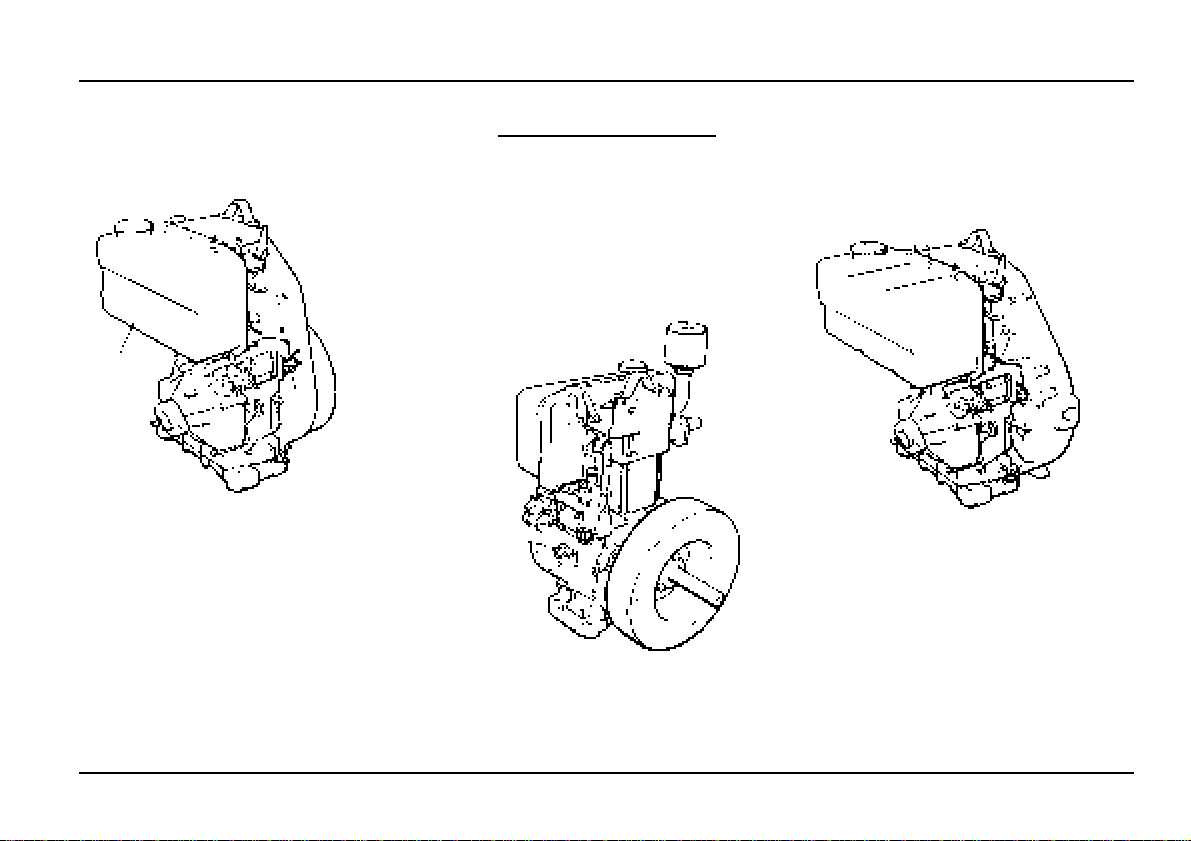
The purpose of this handbook is to lay
downoperatingguidelines forthe LT1 and
LV1 engine ranges.
The specification details given apply
to a range of engines and not to any one
particular engine, in cases of difficulty the
user should consult the local Lister Petter
DistributororDealer forfurtheradvice and
technical assistance.
The information, specifications,
illustrations, instructions and statements
contained within this publication are given
with our best intentions and are believed
to be correct at the time of going to press.
Our policy is one of continued
development and we reserve the right to
amend any technical information with or
without prior notice.
Whilst every effort is made to ensure
the accuracy of the particulars contained
within this publication neither the
Manufacturer, Distributor or Dealer shall
inanycircumstances beheld liableforany
inaccuracy or the consequences thereof.
The information given is subject to the
Company’s current Conditions of Tender
and Sale, and is for the assistance of
users and is based upon results obtained
from tests carried out at the place of
manufacture. This Company does not
guarantee that the same results will be
obtained elsewhere under different
conditions.
Using this Operators Handbook
It is recommended the individual
steps contained in the various
maintenance or repair operations are
followed in the sequence in which they
appear.
When a diesel engine is operating or
being overhauled there are a number of
associated practices which may lead to
personal injury or product damage.
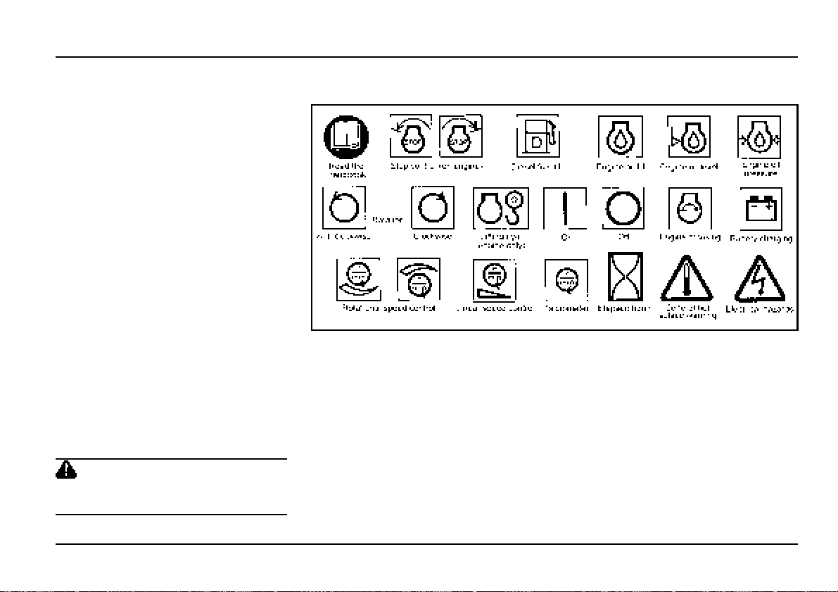
Your attention is drawn to the symbols
shown and described below which are
applied throughout this publication.
CAUTION
This caution symbol draws attention to
special instructions or procedures which,
if not correctly followed, may result in
damage to or destruction of equipment.
WARNING
This warning symbol draws attention to
special instructions or procedures which,
if not strictly observed, may result in
personal injury.
WARNING
A WARNING SYMBOL WITH THIS
TYPE OF TEXT DRAWS ATTENTION
TO SPECIAL INSTRUCTIONS OR
PROCEDURES WHICH, IF NOT
STRICTLY OBSERVED, MAY RESULT
IN SEVERE PERSONAL INJURY, OR
LOSS OF LIFE.
Running-in
A gradual running-in of a new engine
is not necessary. Extended light load
running early in the life of the engine may
cause detrimental damage to the cylinder
bore allowing lubricating oil to enter the
exhaust system.
To help assist engine running-in, all
engines are despatched with an initial fill
lubricating oil which must be changed
after 100 hours.
Associated Publications
Workshop Manual ............... P027-09207
Master Parts Manual ........... P027-08043
Technical Handbook ........... P027-09212
Introduction
Introduction

Lister Petter LT and LV Operators Handbook page 3
Engine Features
- LT1 and LV1
Engine Features
LT1
Fuel tank
Engine lifting eye
Lubricating
oil filler
LT1 Build 32
Dipstick
Air Cleaner
Fuel
pump
LV1
Decompressor leverFuel tank filler

Lister Petter LT and LV Operators Handbookpage 4
1. General Information
- safety precautions
1.1 Safety Precautions
The following safety precautions are of
ageneral nature,morespecificprecautions
appear where they are relevant.
1.1.1 General Precautions
• Ensure the engine is securely
mounted.
• Ensure that there is a generous supply
ofcooling andcombustion airavailable.
• Keeptheengine andsurroundingarea
clean.
• Keep all safety guards in position.
• Keep the body and clothing clear of all
moving or hot parts.
• Never allow any part of the body to
come into contact with high pressure
fuel oil, for example when testing fuel
injection equipment.
• Thoroughlyclean anylubricating orfuel
oil from the skin as soon as possible.
• Rectify all fuel, water and oil leaks as
soon as practicable and clean any
spillages when they occur.
1.1.2 Before Starting Precautions
WARNING
Starting any diesel engine can be
dangerous in the hands of inexperienced
people. Engine operators must be
instructedinthe correctproceduresbefore
attempting to start any engine.
• Ensurethe engineisfreetoturn without
obstruction.
• Check that the lubricating oil level is
correct.
• The oil sump must be filled to the ‘full’
mark on the dipstick; do not overfill.
• Check thatthe fuelsupply isadequate
and the system is primed.
• Ensure that the battery is connected,
fully charged and serviceable.
• Where possible, disengage the driven
equipment while starting.
1.1.3 Charge Winding Precautions
The following points must be strictly
observed when charge windings
are fitted otherwise serious damage can
be done.
• Neverremove anyelectricalcable while
the battery is connected in the circuit.
• Only disconnect the battery with the
engine stopped and all switches in the
OFF position.
• Always ensure that cables are fitted to
their correct terminals.
Ashortcircuit orreversal ofpolarity will
ruin diodes and transistors.
• Neverconnect abatteryintothesystem
without checking that the voltage and
polarity are correct.
• Never flash any connection to check
the current flow.
• Never experiment with any
adjustments or repairs to the system.
• The battery and charge windings must
be disconnected before commencing
any electric welding when a pole strap
isdirectlyor indirectlyconnected tothe
engine.
WARNING
Startingenginesthat are fittedwithcharge
windings which have been disconnected
from the battery will cause irreparable
damage unless the stator leads from the
rectifier/regulator have been removed.
1.1.4 Starter Battery Precautions
• Do not smoke near the batteries.
• Keepsparksandflamesaway fromthe
batteries.
• Batteries contain sulphuric acid - if the
acid has been splashed on the skin,
eyes or clothes flush it away with
copious amounts of fresh water and
seek medical aid.

Lister Petter LT and LV Operators Handbook page 5
• Keep the top of the battery well
ventilated during charging.
•
Disconnect the battery negative
(earth) lead first and reconnect last.
• Switch off the battery charger before
disconnecting the charger leads.
• Never 'flash' connections to check
current flow.
• A damaged or unserviceable battery
must never be used.
1.1.5 Lifting Precautions
Thefollowingpoints mustbeconsidered
before attempting to lift the engine.
• Ensuretheliftingequipmenttobeused
has the correct capacity to lift the
engine.
• A single engine lifting eye is fitted .
Suitable lifting equipment designed to
give a vertical lift from directly above the
engine lifting eye must be used.
• Check that the engine lifting eye is not
damaged and is secure.
• The lifting eye fitted to the engine is
suitable for lifting the engine and
accessory assemblies originally fitted
by Lister Petter.
WARNING
Engine lifting eyes must not be used to lift
the complete plant.
1.2 Safety Symbols
This section identifies the ISO 8999 symbols currently used by Lister Petter.
1. General Information
- safety precautions and symbols

Lister Petter LT and LV Operators Handbookpage 6
1.3 Technical Data 1.4 Nomenclature
LT1 - single cylinder, direct injection,
naturallyaspirated,flywheel fanaircooled
diesel engine.
Build 32 is convection cooled.
LV1 - single cylinder, direct injection,
naturallyaspirated,flywheel fanaircooled
diesel engine.
Build 32 is convection cooled.
1.5 Engine Serial Number
The engine serial number is stamped
on a plate attached to the air shield on
the manifold side of the engine. It is
necessary to identify the type and build
of each engine to enable the correct
maintenance procedures, as described
later in this publication, to be carried out.
Typical Serial Number
03 00123 LV1 C 01
Serial Number Code
03 ........... Year code (03=2003)
00123 ..... Consecutive number of engine
LV1 ......... Model
A............. Anti-clockwise rotation
C ............ Clockwise rotation
01 ........... Build of engine
1. General Information
- technical data and engine identification
LT1 LV1
Rotation 1Clock and anti-clock Clock and anti-clock
Type of injection Direct Direct
Number of cylinders 1 1
Electrical system 212v negative earth 12v negative earth
Battery charging system 2Charge windings Charge windings
Oil pressure - minimum bar 0.4 0.4
lbf/in25.8 5.8
Oil sump capacity litres 1.3 1.3
pints 2.3 2.3
US qts 1.3 1.3
Capacity between dipstick
marks
litres 0.2 0.2
pints 0.35 0.35
US qts 0.21 0.21
Fuel tank capacity litres 5.0/8.25 8.25/13.5
pints 8.8/14.5 14.5/23.7
US qts 5.3/8.7 8.7/14.2
Notes:
1. Rotation is dependant on Build - refer to "1.5 Engine Serial Number".
2. Fitted as standardon somebuilds.

Lister Petter LT and LV Operators Handbook page 7
2. Operating Instructions
- preliminary instructions
2.1 Preliminary Instructions
The following operating instructions
areofa generalnature andshould beread
in conjunction with, or substituted by, the
equipment manufacturers instructions.
WARNING
Startinganydieselenginecanbedangerous
in the hands of inexperienced people.
Before attempting to start any engine the
operator should read the "1.1 Safety
Precautions"andbeconversantwiththeuse
oftheenginecontrolsandthecorrectstarting
procedures.
CAUTION
ETHER BASED COLD START AIDS IN
AEROSOL CANS MUST NOT BE USED
UNDER ANY CIRCUMSTANCES.
Systems may be fitted to allow a measured
quantitytobeinjectedintotheinletmanifold,
but these must be used in accordance with
the manufacturers instructions.
WARNING
EXHAUST GASES CONTAIN CARBON
MONOXIDE WHICH IS A COLOURLESS,
ODOURLESS AND POISONOUS GAS
THAT CANCAUSEUNCONSCIOUSNESS
AND DEATH.
The engines are able to run
satisfactorily at ambient temperatures up
to 25°C (77°F) without derating. Above
this temperature the rated power must be
reduced in accordance with the relevant
ISO, BS or DIN Standards.
The maximum temperature is 52°C
(125°F) and if it is desired to run at higher
temperatures the local Lister Petter
Distributor or Dealer should be consulted.
2.2 Starting Handle Precautions
A non-limited kick-back handle (A), or
limited kick-back handle (B) system may
be fitted to the engine.
Figure 2.2.1 Starting Handles
• The two types of handle are not
interchangeable and care must be
taken to ensure the correct type is
retained with the engine.
• Always use the correct starting handle
which has been designed for the
engine.
• Ensure there are no burrs on that part
ofthe handlewhich fitsontotheengine.
• Ensure the handle grip is clean, dry
and free to turn on its shaft.
• Clean and lightly oil that part of the
handle which fits onto the engine.
• Firmly hold the handle grip, with the
thumb on top of the grip, during the
starting procedure.
WARNING
Do not attempt to use a handle if it is
damaged in any way.

Lister Petter LT and LV Operators Handbookpage 8
2.3 Cold Starting Aid
An optional cold starting aid may be
fitted to the combustion air intake port
for use when the ambient temperature
is below -10°C (14°F).
CAUTION
The device must not be used more than
three times in succession during the same
attempt to start the engine.
1. With the fuel turned on turn the engine
for up to 20 revolutions to prime the
fuel and lubrication systems.
2. Withdraw the plunger (A) and fill one
third of the cup (B) with the same type
of lubricating oil as used in the engine.
Figure 2.3.1 Cold Start
3. Replace the plunger and inject the oil
just before starting the engine.
2.4 Hand Starting
Before attempting to start the engine
referto"2.2 Starting HandlePrecautions".
1. Select the excess fuel position by
gently pulling the engine control lever
(A) outward over the middle catch (B)
and turning it fully clockwise.
Figure 2.4.1 Engine Control
2. If avariable speedcontrol leverisfitted
move it to the fast position.
3. Move the decompressor lever towards
the flywheel.
Figure 2.4.2 Decompressor Lever
4. If the ambient temperature is below -
10°C (14°F) refer to "2.3 The Cold
Starting Aid".
5a.If using a non-limited kick-back
handle:
Insert the correct handle, refer to 'A' in
'Figure2.2.1StartingHandles',into the
starting housing.
Slowlyrotate thehandle inthe direction
of cranking until it fully engages.
5b.If using a limited kick-back handle:
Swivel the starting handle housing
cover (C) to one side, lift the spring
loaded plunger (D), if fitted, and insert
thecorrecthandle,referto 'B'in 'Figure
2.2.1 Starting Handles', into the
housing.
Slowlyrotate thehandle inthe direction
of cranking until it fully engages.
2. Operating Instructions
- cold start aid and hand starting

Lister Petter LT and LV Operators Handbook page 9
Figure 2.4.3 Starting Handle Housing
6. If the cold starting aid was not used
turntheengineslowlyforupto20turns
to prime the combustion chamber and
lubricating oil system.
7. Firmly hold the handle grip, with the
thumb on top of the grip as shown in
'Figure 2.4.4 Holding the Starting
Handle', and crank the engine really
fast, when sufficient speed is obtained
move the decompressor lever towards
thegear endand continueto crankuntil
the engine fires.
WARNING
Do not pull the starting handle away from
the engine while cranking.
Retaining a firm grip on the handle, lift
the spring loaded plunger (D), if fitted,
and remove the handle from the
housing.
Figure 2.4.4 Holding the Starting Handle
8. Turn the engine control lever anti-
clockwise to the 'RUN' position.
9. If a variable speed control is fitted
reduce the speed as required.
2.5 Electric Starting
If the engine fails to start within 30
seconds, release the start key, or start
button, and attempt to restart after
allowingsufficienttimefor allmoving parts
to stop.
1. Select the excess fuel position by
gently pulling the engine control lever
(A) outward over the middle catch (B)
and turning it fully clockwise.
Figure 2.5.1 Engine Control
2. Check that the decompressor lever is
towards the gear end.
3. If avariable speedcontrol leverisfitted
move it to the fast position.
4. If the ambient temperature is below -
10°C (14°F) refer to items 2. and 3.
in "2.3 Cold Starting Aid".
2. Operating Instructions
- electric starting

Lister Petter LT and LV Operators Handbookpage 10
2. Operating Instructions
- stopping the engine
5. If a start key is being used:
Turn the start key clockwise and hold
it at position ‘3’, until the engine fires
and then release it immediately.
Figure 2.5.2 Start Key
If a starter button is being used:
Pressthe starterbutton untilthe engine
fires and then release it immediately.
6. Turn the engine control lever anti-
clockwise to the 'RUN' position.
7. If a variable speed control is fitted
reduce the speed as required.
2.6 Stopping the Engine
Turn the engine control fully anti-
clockwise to the ‘STOP’ position and hold
it there until the engine comes to rest.
After the engine has stopped ensure
the start key, if fitted, is turned anti-
clockwise to the ‘OFF’ position.
Figure 2.6.1 Engine Control
CAUTION
Turning thekeyswitchto the‘OFF’position
will not stop the engine.
CAUTION
Never stop the engine by operating the
decompressor lever or valve damage may
occur.

Lister Petter LT and LV Operators Handbook page 11
3. Engine Fluids
3.1 Oil Specification
To help assist engine running-in, all
engines are despatched with an initial fill
lubricating oil which must be changed
after 100 hours.
All subsequent oil changes must be
as specified in "4.13 Maintenance -
schedule hours".
CAUTION
Some of the following classifications may
not be available in your country. In cases
of difficulty, it is suggested contact be
made with a reputable oil supplier or any
Lister Petter Distributor.
1. The temperatures mentioned in the
tables are the ambient temperatures at
the time when the engine is started.
However,ifmonogradeoilsareusedand
running ambient temperatures are
significantly higher than starting
temperatures, a higher viscosity oil
shouldbeselectedsubjecttosatisfactory
starting performance. Multigrade oils
may be used to overcome the problem.
2. Where it is not practical to continually
change oils to suit varying ambient
temperatures, a suitable multigrade oil
is recommended to ensure adequate
starting performance at the lowest
temperature likely to be encountered.
3. ’L’ Series engines must be run on
heavy duty lubricating oils that at least
meet the requirements of one of the
following:
API CC MIL-L-46152B
DEF2101D MIL-L-2104B
Straight mineral oils are not suitable,
neither are oils of less detergency than
specified.
Note:
Higher specification oils meeting API CD,
APICEand API CF-4aremore commonly
available than API CC. The use of these
oils in new engines is acceptable for
topping up the 'first fill' and following the
first 100 hours when running-in has been
completed.
These oils are particularly suited to
engines running at a high load factor, or in
conjunction with high ambient
temperatures. They must also be used
where the sulphur content of the fuel
exceeds 0.5%.
CAUTION
API CD, API CE, API CF-4 or MIL-L-
2104C/D/E oils can inhibit the running-in
process in new or reconditioned engines
and are not suitable for engines running
on low duty cycles.
4. The oil must be suitable for 250 hour
oilchanges withoutundue degradation,
with sump temperatures reaching
150°C (302°F) under severe tropical
conditions, and 120°C (248°F) under
normal conditions.
5. For engines in long running
installations Lister Petter should be
consulted.
3. Engine Fluids
- oil specification

Lister Petter LT and LV Operators Handbookpage 12
3.3 Oil Viscosity
The following chart shows the correct
oil viscosity for various °C
ambient
temperature ranges for cold start to
maximum running temperatures.
Before selecting a viscosity grade
refer to Notes:
Notes:
A. Intermittent running.
B. Synthetic oils only.
°F = (1.8 x °C) + 32.
1. SAE 5W-20 oils are recommended on
the basis that they are fully synthetic,
and are technically suitable for use up
to 25°C (77°F). Non synthetic oils at
very low temperatures will suffer from
wax crystallisation.
Monograde SAE 5W is not normally
availableasasyntheticoilandtherefore
is not quoted.
3. Engine Fluids
- oil viscosity and fuel specification
2. In order to maintain the cold starting
characteristics of any recommended
grade, it is essential that oil changes
are made within the Lister-Petter
recommendations.
An oil change is recommended
immediately if the engine fails to reach
itsnormalcold startcranking speeddue
to excessive oil viscosity.
Fuel dilution of the lubricating oil will
adversely affect cold starting and oil
consumption.
3. SAE 30 and 10W-30 oils may be used
at up to 52°C (126°F) but oil
consumption may be affected.
10W-40, 15W-40 and 20W-40
multigrade oils are recommended for
continuous full load operation at this
temperature.
4. Monograde SAE 40 oils are not
recommended.
3.4 Fuel Specification
The engine must only be used with
diesel fuel oil which conforms to one of
the following:-
a. BS 2869:1988 Class A2.
b. BS EN590:1995 Class A1.
c. USA Specification ASTM D-975-77
Grades No.1-D and 2-D.
d. BSMA 100 Class M1 for marine use.
The fuel must be a distillate, and not
a residual oil or blend. Vaporising oils are
not suitable as fuels for these diesel
engines.
The user is cautioned that although
the engines may operate on fuels outside
the above specifications, such operation
may well result in excessive wear and
damage.
CAUTION
The fuel injection equipment is
manufactured to very accurate limits and
the smallest particle of dirt will destroy its
efficiency.
Fuel, free from water and contaminants is
of the utmost importance.
3.5 Fuel in Low Temperatures
Specialwinterfuels areoftenavailable
for use at ambient temperatures below
0°C (32°F).
Thesefuelshave alowerviscosity and
limit the formation of wax at low ambient
temperatures.
CAUTION
Wax formation can rapidly reduce the flow
of fuel through the fuel filter element.

Lister Petter LT and LV Operators Handbook page 13
4.1 Preliminary Instructions
These recommendations and
instructions cover LT and LV engines
therefore they are of a general nature and
may include optional equipment not
specifically covered in this book.
Moredetailed informationcan befound
in the Workshop Manual or any Lister
Petter Diesel distributor can be consulted.
• The engine should receive regular
attention during the first 50 hours of its
lifefromnewandafteramajoroverhaul.
• Long periods of light or ‘no load’
running early in the engine’s life may
lead to cylinder bore glazing and high
oil consumption.
• The instructions given in "4.13
Maintenance - schedule hours" are
based on average operating conditions
and cover the minimum requirements
to keep an engine running at peak
performancewithtroublefreeoperation.
• Under very dusty conditions, air
cleaners, lubricating oil and fuel filters
will require more frequent attention.
• Decarbonising may be required more
often if the engine has been running
on light loads for long periods.
• Before carrying out any maintenance
work on an engine it is advisable to
remove the battery.
The battery and charge windings must
be disconnected before commencing
any electric welding when a pole strap
isdirectlyor indirectlyconnected tothe
engine.
• It is essential to ensure that nuts and
bolts are tightened to the torques
specified in the Workshop Manual.
• When re-assembling an engine
lubricate all moving parts with engine
oil.
• Renew nuts and bolts that have been
taken from high stress locations.
In particular nuts and/or bolts from the
connecting rods should be renewed.
• The fuel injector can only be checked
and set off the engine using suitable
specialist test equipment.
WARNING
ON NO ACCOUNT ALLOW ANY
UNPROTECTED SKIN TO COME INTO
CONTACTWITHTHE INJECTORSPRAY
AS THE FUEL MAY ENTER THE BLOOD
STREAM WITH FATAL RESULTS.
WARNING
SOME ENGINES MAY BE FITTED WITH
SEALS OR ‘O’ RINGS MANUFACTURED
FROM‘VITON’OR ASIMILARMATERIAL.
WHEN EXPOSED TO ABNORMALLY
HIGH TEMPERATURES, IN EXCESS OF
400°C (752°F), AN EXTREMELY
CORROSIVE ACID IS PRODUCED
WHICH CANNOT BE REMOVED FROM
THE SKIN.
IF SIGNS OF DECOMPOSITION ARE
EVIDENT, OR IF IN DOUBT, ALWAYS
WEAR DISPOSABLE HEAVY DUTY
GLOVES.
4.1.1 Before Starting Work
Before starting any dismantling
procedure the following should be
considered:
• Do you know and understand the
engine and all the related systems?
• Do you have sufficient electrical and
mechanical knowledge and skills to
understand the symptoms?
• Do you have suitable electrical
diagnostic equipment available?
• Do you have, or access to, the
necessary Lister Petter spare parts
before you commence dismantling.
4. Engine Servicing
- preliminary instructions
4. Engine Servicing

Lister Petter LT and LV Operators Handbookpage 14
4.2 Precautions for Filters and
Elements
• Particular attention is drawn to the
instructions given later in this section
for replacing filters.
• Usedliquid filtersand elementscontain
some of the filtered liquid and should
be handled and disposed of with care.
• After handling new or used elements
the users hands should be thoroughly
washed, particularly before eating.
WARNING
Fuel and new or used lubricating oil may
cause skin irritation.
WARNING
Thematerialsusedinthe manufactureand
treatmentof somefilters andelements may
cause irritation or discomfort if they come
into contact with the eyes or mouth and
they may give off toxic gases if they are
burnt.
WARNING
Care must be taken to ensure that waste
fuel, oil and filter elements are disposed
of in accordance with local regulations to
prevent contamination.
4.3 Initial Attention
To help assist engine running-in, all
engines are despatched with an initial fill
lubricating oil which must be changed
after 100 hours.
All subsequent oil changes must be
as specified in "4.13 Maintenance -
schedule hours".
It is recommended that the following
receive attention after the engine has run
50 hours and again after 250 hours.
• Adjust the valve clearances, if
necessary.
• Check and tighten nuts, bolts and
unionspaying particularattention tothe
fuel system.
• Check the lubricating oil level and top
up if necessary.
• Observe the exhaust at the normal full
load.
The exhaust must be free from soot. A
black exhaust means that the engine
is overloaded or that the injection
equipment is out of order.
Do not allow the engine to run with a
dirty exhaust without investigating the
cause as this may result in an
expensive breakdown.
• Following the initial attention, routine
maintenance must be carried out as
specified in "4.13 Maintenance -
schedule hours".
4.4 Priming the Fuel System
Iftheengine is fittedwitha selfpriming
fuel system it should not be necessary to
prime the system.
Figure 4.4.1 Priming the Fuel System
1. Fill the fuel tank.
2. Move the engine control lever to the
‘RUN’ position.
3. Vent the fuel filter through the bleed
screw (A) until a full air free flow of fuel
is obtained.
4. Vent fuelat thepump throughthe bleed
screw (B) until a full air free flow of fuel
is obtained.
4. Engine Servicing
- precautions, initial attention and priming

Lister Petter LT and LV Operators Handbook page 15
4.5 Valve Clearance Adjustment
The valve clearance for both inlet and
exhaust valves must be set with the
engine cold.
1. Remove the cylinder head cover.
2. Ensure the cylinder head nuts are
correctly tightened.
3. Turn the flywheel until the piston is at
the TDC position on the firing stroke;
TDC is marked on the flywheel.
4. Slacken the locknut (A) and adjust the
screw (B) until the correct clearance
has been obtained.
GO - 0.10mm (0.004in).
NOT GO - 0.15mm (0.006in).
Figure 4.5.1 Setting the Valve Clearance
5. Tighten the locknut whilst restraining
the adjusting screw and re-check to
ensure the clearance is correct.
6. Repeat for the remaining valve.
7. Replace the rocker cover taking care
to ensure the decompressor lever is
vertical.
4. Engine Servicing
- valves and decompressor adjustment
4.6 Decompressor Adjustment
This adjustment should only be made
when the valve clearance is correctly
adjusted.
1. Remove the cylinder head cover.
2. Turn the flywheel until the piston is at
the TDC position on the firing stroke;
TDC is marked on the flywheel.
3. Adjust the screw (A) until the exhaust
valve just begins to move downwards
when the lever is vertical.
4. Turnthescrew afurther turn clockwise
so that it travels towards the rocker.
Figure 4.6.1 Decompressor Adjustment
5. Replace the rocker cover taking care
to ensure the decompressor lever is
vertical.

Lister Petter LT and LV Operators Handbookpage 16
4.7 Air Cleaner - Build 32
1. Slacken the clip (A).
2. Remove the cleaner (B) from the
manifold (C).
Figure 4.7.1 Air Cleaner - Build 32
3. Fit a new cleaner assembly.
4.8 Air Cleaner - electric start
Builds
1. Remove the air cleaner from the
manifold by removing the centre bolt
(A) taking care to retain the copper
washer.
Figure 4.8.1 Air Cleaner
2. Remove the cover (B) by unscrewing
the centre bolt (C).
3. Remove the old element (D) and fit a
new one.
4. Engine Servicing
- air cleaner
4.9 Air Cleaner - other Builds
1. Remove thecover (A) byremovingthe
centre bolt.
Figure 4.9.1 Air Cleaner
2. Remove the old element (B) and fit a
new one.

Lister Petter LT and LV Operators Handbook page 17
4.10DrainingandFillingtheOilSump
Before draining the oil read, "4.2
Precautions for Filters and Elements".
CAUTION
Do not overfill with lubricating oil as this
may have a detrimental effect on engine
performance.
1. If possible run the engine immediately
before draining the oil.
2. Place a suitable container under the
drain plug.
3. Remove the drain plug (A).
Figure 4.10.1 Oil Drain
4. Clean and coat the threads of the
flanged drain plug with Wellseal and
the tapered plug with Hylomar PL32/
M or Three Bond 1110B.
5. Replace the drain plug taking care not
to over-tighten it.
6. Fill the sump through the oil filler to the
top mark on the dipstick (B).
Figure 4.10.2 Oil Filler
7. Start theengine,runitfor afew minutes
andcheckthedrainplug doesnot leak.
8. Stop the engine, allow the oil to settle
and check the level on the dipstick.
9. Add more oil if necessary.
Oil Sump Capacity
litres pints US qts
LT1 1.3 2.3 1.3
LV1 1.3 2.3 1.3
Capacity Between Dipstick Marks
litres pints US qts
LT1 0.20 0.35 0.21
LV1 0.20 0.35 0.21
4. Engine Servicing
- draining the sump

Lister Petter LT and LV Operators Handbookpage 18
4.11 Changing the Fuel Filter
Before changing the filter, read "4.2
Precautions for Filters and Elements".
1. Remove the retaining bolt or plug (A).
2. Remove the old element (B) and joints
(C).
3. Fit a new element and new joints.
4. Replace and tighten the retaining bolt
or plug (A).
5. Prime the fuel system.
Figure 4.11.1 Fuel Filter Elements
4.12 Checking the Battery
1. Wear protective gloves and goggles.
2. Clean the top of the battery filler plug
area.
3. Remove the filler plugs and check that
theelectrolyte levelis 6.0-9.0mm(0.25-
0.37in) above the tops of the
separators.
4. If necessary top up with distilled water.
In cold weather distilled water should
only be added immediately before
running the engine.
5. Replace and tighten the filler plugs.
6. Check that the terminal connections
are tight; petroleum jelly will help to
protect them from corrosion.
WARNING
BATTERIES CONTAIN SULPHURICACID
WHICH CAN CAUSE SEVERE BURNS
AND PRODUCE EXPLOSIVE GASES.
IF THE ACID HAS BEEN SPLASHED ON
THE SKIN, EYES OR CLOTHES FLUSH
WITH COPIOUS AMOUNTS OF FRESH
WATER AND SEEK IMMEDIATE
MEDICAL AID.
4. Engine Servicing
- fuel filter and battery

Lister Petter LT and LV Operators Handbook page 19
4. Engine Servicing
- schedule hours and troubleshooting
Every 500 Hours
The above and the following items.
Replace the air cleaner element.
Examine the exhaust and induction
systemsforleaks,damageor
restrictions.
Renew the fuel filter element.
Check the battery charge winding
system; refer to the Workshop Manual.
Every 1000 Hours
The above and the following items.
Check the valve clearances.
Decarbonise if the engine performance
has deteriorated.
Clean the cylinder barrel and head fins.
Cleanthe banjo unionatthe cylinderhead
end of the oil feed pipe.
Every 2000 Hours
The above and drain, flush and refill the
fuel tank.
4.13 Maintenance - schedule hours
To help assist engine running-in, all
engines are despatched with an initial fill
lubricating oil which must be changed
after 100 hours.
All subsequent oil changes must be
as specified below.
Daily
Check the fuel and lubricating oil levels.
Check for oil and fuel leaks.
Clean, orreplace,the aircleanerelement
under very dusty conditions.
Every 125 Hours
The above and the following items.
Checktheconditionofthebattery,iffitted.
Clean or replace the air cleaner element
under moderately dusty conditions.
Every 250 Hours
The above and the following items.
Drain the sump and refill with new oil of
the correct type and specification as
given in "3.1 Oil Specification".
Clean or replace the injectors if the
exhaust is dirty.
Renew the fuel filter element if the fuel
being used is not perfectly clean.
4.14 Troubleshooting
Troubleshooting mechanical engine
problemscanbe difficult.This sectionlists
possible engine problems that could be
encountered with possible causes. The
information given is of a general nature
as it covers the basic engine and your
particular application may be different.
If you are in any doubt, contact your
local Lister Petter distributor.
Before starting any dismantling
procedure the following should be
considered:
a. Do you know and understand the
engine and all the related systems?
b. Do you have sufficient electrical and
mechanical skills and knowledge to
understand the symptoms?
c. Do you have suitable electrical
diagnostic equipment available?
d. Do you have, or access to, the
necessary Lister Petter spare parts
before you commence dismantling.

Lister Petter LT and LV Operators Handbookpage 20
4. Engine Servicing
- troubleshooting
Difficult Starting
Stop/start lever in the wrong position.
Decompressor lever in the wrong
position.
Incorrect type of fuel or oil.
No fuel in the tank.
Choked fuel filter or air cleaner.
Air lock in the fuel system.
Incorrect decompressor clearance.
Battery not serviceable.
Loose electrical connection.
Load not disconnected.
Turning the crankshaft the wrong way.
Method of Troubleshooting
1. Diagnose the problem by eliminating
the easiest things first.
2. Before starting to remove or dismantle
any components double check your
observations.
3. When electrical troubleshooting
always start at the battery first.
Exhaust Smoke
White smoke - generally as a result of
water in the fuel.
Faint blue smoke - appears with light
load.
Heavy blue smoke - caused by
lubricating oil passing the piston rings
due to stuck, worn or broken rings or a
worn cylinder.
Black smoke due to incomplete
combustion of the fuel can be caused
by overload, choked air filter, inlet air
temperature too high or incorrect
specificationof fuel.
Overheating
Air inlet obstructed.
Overload
Lubricating oil level too low.
Hunting
Air in the fuel system.
Engine Stops
Lack of fuel.
Air in the fuel system.
Choked fuel filter.
Excessive overload.
Overheating.
Loss of compression.
Loss of oil. Loss of Power
Incorrect tappet clearance.
Choked air cleaner or fuel filter.
Choked exhaust system.
Failure to Attain Normal Speed
Engine started on overload.
Fuel system not correctly primed.
Insufficient fuel. Knocking
Loose coupling or pulley.
Engine loose on its mounting.
Incorrect specification of fuel.
This manual suits for next models
2
Table of contents
Other Lister Petter Engine manuals

Lister Petter
Lister Petter GW3 Service manual

Lister Petter
Lister Petter alpha Series Service manual

Lister Petter
Lister Petter ALPHA LPW2 Service manual

Lister Petter
Lister Petter T Series Service manual

Lister Petter
Lister Petter T Series Service manual

Lister Petter
Lister Petter TS1 Instruction manual

Lister Petter
Lister Petter K1 64 Service manual

Lister Petter
Lister Petter T Series Service manual

Lister Petter
Lister Petter alpha Series Service manual

Lister Petter
Lister Petter alpha Series Instruction manual