Lister Petter alpha Series Service manual

LPW/LPWS/LPWX ENGINE
OPERATORS' HANDBOOK
P027-08270
ALPHA SERIES / NEW ALPHA SERIES
ORIGINAL INSTRUCTIONS

2
Associated Publications
Master Parts Manual P027-08041
LPWX4 Master Parts Supplement P027-10641
Workshop Manual P027-08240
Technical Handbook P027-08247
Statement of Indemnity
The information, specications, illustrations,
instructions and statements contained
within this publication are given with our
best intentions and are believed to be
correct at the time of going to press.
Our policy is one of continued development
and we reserve the right to amend any
technical information with or without prior
notice.
Whilst every effort is made to ensure the
accuracy of the particulars contained within
this publication, neither the Manufacturer,
the Distributor nor the Dealer shall in
any circumstances be held liable for any
inaccuracy or the consequences thereof.
The information given is subject to the
Company’s current Conditions of Tender
and Sale; is for the assistance of users; and
P027-08270
Copyright: Lister Petter Ltd, Dursley,
Gloucestershire GL11 4HS, England
is based upon results obtained from tests
carried out at the place of manufacture. This
Company does not guarantee that the same
results will be obtained elsewhere under
different conditions.
Parts that have not been approved by the
Lister Petter organisation cannot be relied
upon for correct material, dimensions or
finish. The Company cannot therefore
be held responsible for any damage
arising from the use of such parts, and the
guarantee will be invalidated.

3
CONTENTS
Introduction.................................................................................. 5
1. Safety Information ................................................................... 7
2. Technical Data....................................................................... 13
3. Starting and Stopping............................................................ 14
4. Engine Fluids......................................................................... 17
5. Routine Maintenance............................................................. 19
6. Troubleshooting ..................................................................... 27
7. Maintenance Record ............................................................. 29
8. Warranty ................................................................................ 37
9. Index...................................................................................... 39

4
LPW / LPWS / LPWX ENGINE OPERATORS' HANDBOOK
2.1 Features of the LPW
series diesel engines
Oil Filter
Oil Filter
Adaptor
Fuel
Filter
Turbocharger
Lifting Eye
Radiator
Fan
LPW(S)T4
Alternator
Flywheel
Inlet
Manifold
Starter
Motor
Exhaust
Manifold
LPW(X)3
Radiator Fan
(may have 6 blades)
Exhaust
Manifold
Flywheel
Housing
Sump
Drain Plug
Inlet
Manifold
Oil
Filter
Fuel
Filter
LPWS2
Glow
Plugs

5
LPW / LPWS / LPWX ENGINE OPERATORS' HANDBOOK
INTRODUCTION
This handbook explains the operation
and routine maintenance of Lister Petter
water cooled diesel engines in the Alpha
(LPW, LPWX) and New Alpha (LPWS)
series.
Please note that If your engine is part
of a generating set, there is a separate
operators' handbook for the genset,
to explain such features as the control
module.
ENGINE IDENTIFICATION
To identify which model of Lister Petter
LPWX/LPW(S) diesel engine you are
using refer to the engine serial number,
which is stamped on a plate attached to
the engine. It identifi es the type and build
of the engine (see table below) to enable
the correct maintenance procedures to
be carried out. Here is a sample serial
number:
06 001234 LPWS3 A 402
06........................Year code (06 = 2006)
001234...............Unique engine number
LPWS3 ............................ Engine model
A .........................Anti clockwise rotation
402....................................Build number
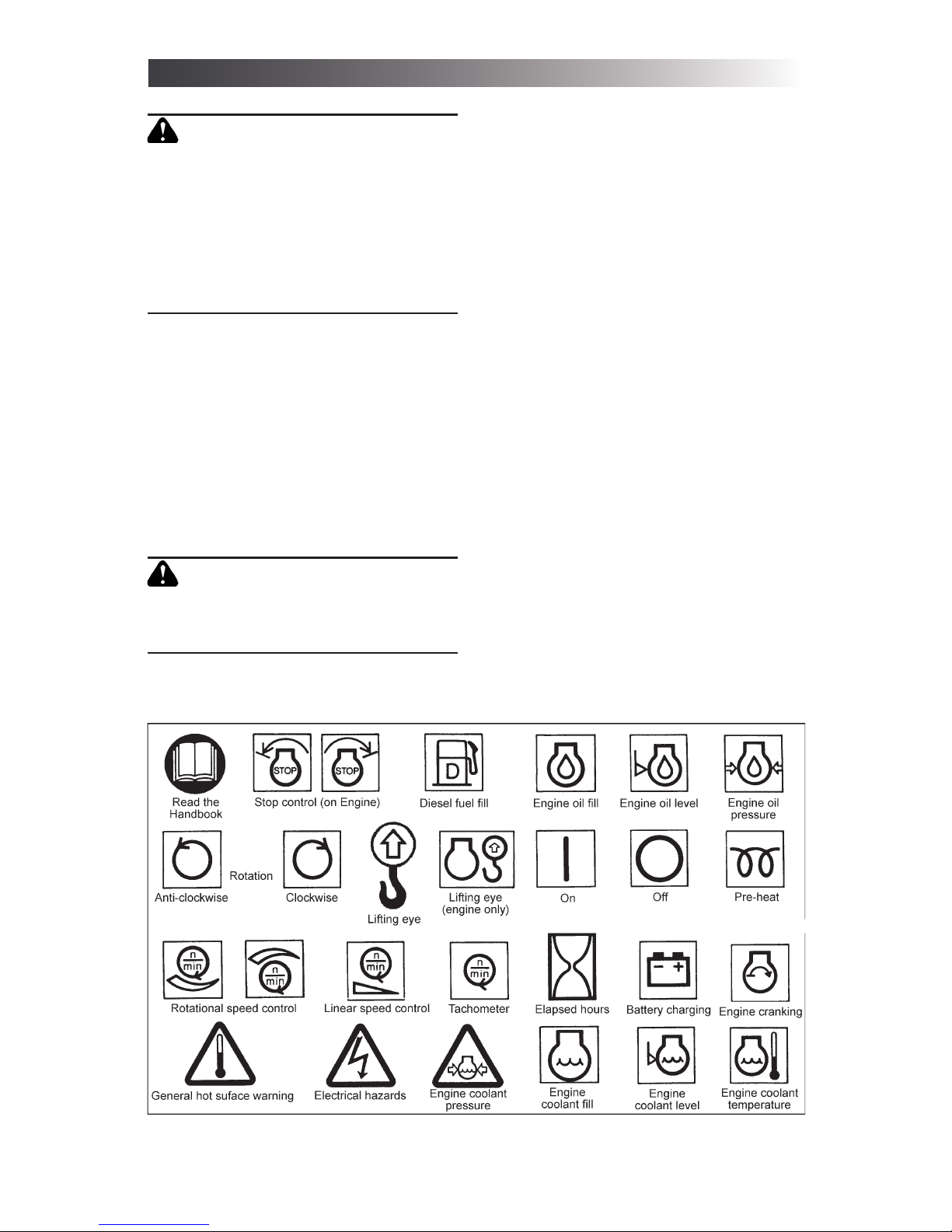
The illustrations on page 4 show features
of the different engine models. When
following the instructions in this handbook
you will need to be familiar with the parts
labelled.
USING THIS HANDBOOK
Operating or servicing a diesel engine
is potentially dangerous. You must not
attempt it unless you have the necessary
knowledge and experience.
Read each section thoroughly and
carefully, taking note of all the information
and instructions given. This is for
your safety and to ensure the correct
maintenance of your engine. For specifi c
aspects of operation and maintenance,
use the table of contents (page 3) or the
index (page 40) to fi nd the section you
need. Where instructions are numbered
in sequence, they must be followed in
LPW DIESEL ENGINE MODELS
Model Characteristic features
LPW2 Two cylinders, water cooled, naturally aspirated, direct injection
LPW3 Three cylinders, water cooled, naturally aspirated, direct injection
LPW4 Four cylinders, water cooled, naturally aspirated, direct injection
LPWT4 Four cylinders, water cooled, direct injection, turbocharged
LPWX2 Two cylinders, water cooled, naturally aspirated, direct injection
LPWX3 Three cylinders, water cooled, naturally aspirated, direct injection
LPWX4 Four cylinders, water cooled, naturally aspirated, direct injection
LPWS2 Two cylinders, water cooled, naturally aspirated, indirect injection, emission compliant
LPWS3 Three cylinders, water cooled, naturally aspirated, indirect injection, emission compliant
LPWS4 Four cylinders, water cooled, naturally aspirated, indirect injection, emission compliant
LPWST4 Fourcylinders,watercooled,naturallyaspirated,indirectinjection,turbocharged,emissioncompliant

6
LPW / LPWS / LPWX ENGINE OPERATORS' HANDBOOK
that order. This applies in particular to
maintenance and repair procedures
(sections 5 and 6).
In cases of diffi culty, or to obtain spare
parts, please consult your local Lister
Petter distributor or dealer.
RUNNING-IN
To assist running-in all engines are
despatched with an initial fi ll lubricating
oil which must be changed after 100
hours. Your engine does not require
gradual light-load running-in. Extended
light-load running should be avoided, as
this could damage the cylinder bore and
allow lubricating oil to enter the exhaust
system.

7
LPW / LPWS / LPWX ENGINE OPERATORS' HANDBOOK
Read the information in this section
carefully and follow all the advice
given. Pay especial attention to the
cautions and warnings demonstrated
below, which are used throughout this
handbook.
CAUTION
This caution draws attention to
special information or procedures
which must be correctly observed,
to avoid damage to, or destruction
of, equipment.
WARNING
This warning draws attention to
special information or procedures
which must be strictly observed.
Failure to do so may result in
personal injury.
WARNING
This WARNING DRAWS ATTENTION
TO SPECIAL information OR
PROCEDURES WHICH must be
strictly OBSERVED. Failure to do
so may result in serious injury or
death.
1.1 GENERAL SAFETY
INFORMATION
Starting and operating any diesel
engine is potentially dangerous. Do not
attempt to do so unless you have the
necessary knowledge and experience.
Ensure that anyone attempting to start
and operate your diesel engine has
been properly trained and instructed
in the correct procedures.
CAUTION
Follow all safety instructions
accurately.
Carefully read and follow all safety
information and instructions in this
manual.
Observe the safety and informative
symbols on your engine and
equipment.
Emergency Precautions
• Be prepared with suitable equipment
and knowledge in case a fi re starts.
• Identify a location from which calls
to the emergency services can be
made if necessary.
• Ensure a third party knows where
you are working and when you leave
the working area.
General Precautions
• Ensure the engine is securely
mounted.
• Ensure that there is a generous
supply of cooling and combustion air
available.
• Keep the engine and surrounding
area clean.
• Some accessories may require
guards which must be supplied and
fi tted by the purchaser. Keep all safety
guards in position.
• Do not make any unauthorised
modifi cations as these may affect the
safe operation of the engine and put
the operator at risk.
1.2 PERSONAL SAFETY
• Wear personal protective clothing
and safety equipment appropriate to
the work being done.
• Keep clear of moving parts at all
times.
1. SAFETY INFORMATION

8
LPW / LPWS / LPWX ENGINE OPERATORS' HANDBOOK
1. Safety Symbols This gure identi es the ISO 8999 symbols currently used by Lister Petter
WARNING
KEEP THE BODY AND CLOTHING
CLEAR OF MOVING OR HOT PARTS
ATALLTIMES.CONTACTOFMOVING
PARTS WITH UNPROTECTED SKIN
CAN CAUSE SEVERE BURNS.
ENTANGLEMENT WITH ROTATING
EQUIPMENT CAN CAUSE SERIOUS
INJURY OR DEATH.
• Tie long hair back securely.
• Wear close-fi tting clothing.
• Do not wear a necktie, scarf, loose
clothing or necklace when working
close to a running engine.
• Where possible, remove rings and
other jewellery to prevent entanglement
in moving parts. These items could also
cause a short circuit if any part of the
electrical system is being worked on.
WARNING
Prolonged exposure to loud noise
can cause impairment, or loss, of
hearing.
• Wear suitable ear protection against
objectionable or uncomfortable loud
noise.
• To avoid loss of concentration, do
not use music or radio headphones
while operating an engine.
• When undertaking maintenance, do
not work under any plant that is only
held by overhead lifting equipment.
• Where appropriate, make sure that
guards are properly fi tted.
1.3 PRECAUTIONS WITH
CHEMICALS
Protect yourself from exposure to
hazardous chemicals at all times, as
this can cause serious injury. Potentially
hazardous chemicals include lubricants,
fuel, coolant concentrate, battery acid,
paint and adhesives.
Manufacturers' safety data sheets
will provide specific details of the
physical and health hazards, safety
and emergency procedures and

9
LPW / LPWS / LPWX ENGINE OPERATORS' HANDBOOK
any necessary personal protection
equipment required while working with
hazardous materials.
• Handle fluids with care at all
times.
• Rectify any fuel, coolant or oil leak
as soon as is practicable and clean up
any spillages when they occur.
• Remove any build-up of grease, oil
or debris.
• If any fl uid other than lubricating
oil comes into contact with the skin,
clean off immediately. In the case of
lubricating oil, clean off as soon as is
practicable.
Fuel and High Pressure Fluids
• Store fuel and other flammable
liquids away from fi re hazards.
• Always stop the engine before
refuelling.
• Do not overfi ll the fuel tank.
• When working with fuel do not
smoke or work near to heaters or other
fi re hazards.
• High pressure fl uids are extremely
hazardous. Never allow any part of the
body to come into contact with high-
pressure fuel oil, compressed air or
hydraulic oil, for example when testing
fuel injection equipment.
WARNING
D o n o t e x p o s e p r e s s u r i s e d
containers to heat, and do not
incinerate or puncture them.
WARNING
NEVER TOUCH OR INGEST HIGH-
PRESSURE FLUIDS SUCH AS
HYDRAULIC OIL, COMPRESSED
AIR OR FUEL OIL. THIS COULD
LEAD TO SERIOUS INJURY, OR
DEATH.
1.4 FUEL SYSTEM
PRECAUTIONS
WARNING
NEVERALLOWANY UNPROTECTED
SKIN TO COME INTO CONTACT WITH
THE INJECTOR SPRAY AS FUEL
MAY ENTER THE BLOODSTREAM
WITH FATAL RESULTS.
WARNING
Never make unauthorised
adjustments to the emission-
compliant fuel injection pumps.
This could be dangerous and
invalidates warranty claims. In the
USA unauthorised adjustment of
emission critical components is
prohibited by Federal Law, incurring
civil penalty.
• When priming or checking the fuel
injection pump timing, care must be
taken to wipe any spilled fuel from the
outside of the engine.
• Always fi t a new joint when a union
has been disturbed.
• Special care must be taken to
see that there is no leakage from the
joints of the fuel pipe connection to the
pump.
• When tightening or loosening fuel
injection pump delivery connections
use two spanners to prevent unsealing
of fuel pump delivery valve holders.
• When refi tting the fuel pipe from the
pump to the injector, the connection to
the injector must be tightened before
the connection to the fuel pump. This
procedure will ensure that there is no
leakage from these joints.
• It is most important that all fuel
joints are tight and leak proof.
• Always fi ll the fuel tank through
a fi ne strainer. It is best to do this at
the end of the engine work period so

10
LPW / LPWS / LPWX ENGINE OPERATORS' HANDBOOK
that any sediment stirred up has time
to settle before the engine is used
again, and the risk of condensation
contaminating the fuel is minimised. If
using a can, avoid tipping out the last
few drops.
• Funnels are very diffi cult to keep
clean in dusty conditions. Wash them
before and after use and wrap them up
when not required, or fi ll the tank direct
from a small-mouthed screw-capped
can.
• The fuel injection equipment is
manufactured to very accurate limits
and the smallest particle of dirt will
destroy its effi ciency.
CAUTION
Keep the fuel free from water and
contaminants.
1.5PRECAUTIONSWITHFILTERS
AND ELEMENTS
• Used fi lters and elements contain
some of the fi ltered liquid and should be
handled and disposed of with care.
• After handling new or used elements,
wash your hands thoroughly.
WARNING
Do not allow fuel or new or used
lubricating oil to come into contact
with unprotected skin. It is dangerous
and could cause skin irritation.
WARNING
Take careful precautions with fi lters
and elements. The materials used in
the manufacture and treatment of
some types may cause irritation or
discomfort if they come into contact
with the eyes or mouth, and they
may give off toxic gases if burnt.
1.6 PRECAUTIONS WITH OIL
SEALS
Some engines may be fi tted with seals
or 'O' rings manufactured from Viton
or a similar material. When these
substances are exposed to abnormally
high temperatures, in excess of 400°C
(752°F), an extremely corrosive acid is
produced.
WARNING
IF AN OIL SEAL CONTAINING
VITON (OR SIMILAR MATERIAL)
DEGENERATES, IT PRODUCES
AN EXTREMELY CORROSIVE ACID
THAT CANNOT BE REMOVED FROM
THE SKIN. IF YOU SEE SIGNS
OF DECOMPOSITION, OR ARE
IN DOUBT, WEAR DISPOSABLE
HEAVY DUTY GLOVES.
• If in any doubt about an oil seal,
always wear disposable heavy duty
gloves.
1.7 PRECAUTIONS WITH
BATTERIES
Batteries contain hazardous sulphuric
acid. Great care therefore needs to be
taken when using them.
• Do not smoke near batteries and
keep sparks and fl ames away from
them. Do not work near to heaters or
other fi re hazards.
• Switch off the battery charger
before connecting or disconnecting
the charger leads. Disconnect the
battery negative (earth) lead fi rst and
reconnect last.
• Keep the top of the battery well
ventilated during charging.
• Never 'fl ash' connections.
• Never use a damaged battery.
• Do not attempt to charge a frozen
battery; it may explode. Instead, warm
the battery to 16°C (60°F).

11
LPW / LPWS / LPWX ENGINE OPERATORS' HANDBOOK
WARNING
Take especial care with batteries,
which contain highly corrosive
sulphuric acid which is poisonous,
will burn skin and clothing, and will
cause permanent damage including
blindness if splashed into the eyes. If
acid accidentally comes into contact
with skin, eyes or clothes, fl ush it
away with copious amounts of fresh
water and seek medical aid.
1.8 PRECAUTIONS WITH
ELECTRICAL SYSTEMS
• Ensure that the battery is of suffi cient
capacity to start the engine down to its
minimum operating temperature, taking
into account any drag that may be
imposed on the engine by the type of
transmission that is attached to it.
• Ensure that the battery and all
engine wiring cables are of suffi cient
size to carry the currents required.
• Check that the engine-mounted
alternator is of suffi cient output to cope
with the total electrical load required by
the machine to which it is fi tted.
Wiring Cables
Ensure that the engine wiring cables are:
• Bound together in a loom and
adequately supported.
• Routed to avoid any hot surfaces,
particularly the exhaust system.
• Not in contact with any rough
surfaces or sharp corners so as to avoid
any possibility of chafi ng taking place.
Alternator
The following points must be strictly
observed when an alternator is fi tted,
otherwise serious damage can be
done.
• Never connect a battery into the
system without checking that the
voltage and polarity are correct.
• Never remove any electrical cable
while the battery is connected in the
circuit.
• Never disconnect the battery
unless the engine has stopped and all
switches are in the off position.
• Always ensure that cables are fi tted
to their correct terminals.
CAUTION
A short circuit or reversal of polarity
will ruin diodes and transistors.
• Never 'flash' any connection to
check the current fl ow.
• Never experiment with any
adjustments or repairs to the system.
• Always disconnect the battery and
alternator before commencing any
electric welding when a pole strap
is directly or indirectly connected to
engine.
1.9 WASTE DISPOSAL
PRECAUTIONS
• Extreme care must be taken
to ensure that waste oil, fuel, filter
elements, coolant concentrate, battery
electrolyte, solvents or other toxic
wastes are disposed of in accordance
with local regulations to prevent
contamination.
WARNING
To avoid contamination and personal
injury, never dispose of toxic or
other waste except in accordance
with offi cial regulations.

12
LPW / LPWS / LPWX ENGINE OPERATORS' HANDBOOK
1.10 PRECAUTIONS BEFORE
STARTING
WARNING
Starting any diesel engine can
be dangerous in the hands of
inexperienced people. Engine
operators must be instructed in
the correct procedures before
attempting to start any engine.
• Ensure that the engine is free to
turn without obstruction.
• Check that the lubricating oil level
is correct. The oil sump must be fi lled
to the ‘full’ mark on the dipstick; do not
overfi ll.
• Check that the radiator is fi lled to
within 13-25 mm (0.5-1.0 in) below the
neck of the radiator fi ller.
• Check that the fuel supply is
adequate and the system is primed.
• Ensure that the battery is connected,
fully charged and serviceable.
• Where possible, disengage the
driven equipment while starting.
1.11 LIFTING PRECAUTIONS
Engine lifting eyes are fi tted to Alpha
and New Alpha engines. The following
points must be considered before
attempting to lift the engine.
• Ensure any lifting equipment to be
used has the correct capacity to lift the
engine.
• Ensure that the lifting equipment
is designed to give a vertical lift from
directly above the engine lifting eye.
• Check that the engine lifting eyes
are not damaged and that they are
secure.
• The engine lifting eyes are suitable
for lifting the engine and accessory
assemblies originally fi tted by Lister
Petter.
WARNING
Engine lifting eyes must not be used
to lift the complete plant.
WARNING
DO NOT WORK UNDER ANY PLANT
THAT IS ONLY HELD BY OVERHEAD
LIFTING EQUIPMENT.
1.12 PRECAUTIONS BEFORE
MAINTENANCE
• Understand the service procedures
before commencing any work.
• Ensure all starting devices are
removed or isolated before beginning
any work on engine or plant.
• Ensure the work area is clean,
dry, well ventilated and has adequate
lighting.
• Ensure that all persons using
equipment or processes in connection
with the maintenance of plant and
machinery have received adequate
and suitable training.

13
LPW / LPWS / LPWX ENGINE OPERATORS' HANDBOOK
2. Technical data for Lister Petter LPW(X) and LPWS engines.
Table 2 gives technical data for all
the engines in the Lister Petter Alpha
(LPW, LPWX) and New Alpha (LPWS)
range.
2.1 COMBUSTION AIR
Engine performance is affected by
ambient temperature, which is taken
to mean the temperature of the air
entering the engine.
The temperature of the combustion air
is measured at the air inlet manifold, or
the air cleaner, and the temperature
of the cooling air is measured at the
radiator fan inlet. The higher of these
two temperatures is taken as being
ambient temperature as far as engine
ratings are concerned.
Every effort should be taken to
ensure that the air cleaner draws in
combustion air at a consistent ambient
2. TECHNICAL DATA
temperature. Lister Petter LPW, LPWX,
LPWT, LPWS and LPWST engines are
able to run satisfactorily at ambient
temperatures up to the standard engine
reference condition of 25°C (77°F)
without derating. If the combustion
air temperature rises above this
temperature, the rated power must
be reduced in accordance with the
relevant standard:
LPW/LPWX/LPWT ISO 3046
LPWS ISO 14396
Generating Sets ISO 8528
The maximum permitted ambient
temperature is 52°C (125°F).
2.2 THE COOLING SYSTEM
Cooling is by a radiator with water
circulation being assisted by an engine
mounted, centrifugal, belt driven water
pump using a single belt.
TECHNICAL DATA
LPW series model LPW(X)2, LPW(X)3, LPW(X)4 LPW(S)T4 LPWS2, LPWS3, LPWS4
Rotation Anti clockwise (when looking on the fl ywheel)
Type of injection Direct Indirect
Firing order:
2 cylinders 1 - 2 n/a 1 - 2
3 cylinders 1 - 2 - 3 n/a 1 - 2 - 3
4 cylinders 1 - 3 - 4 - 2 1 - 3 - 4 - 2 1 - 3 - 4 - 2
Electrical system 12V negative earth
Starter battery charging 12V engine mounted alternator
Oil pressure
at idle 1.0 bar (14.5 lbf in2)
3000
r/min1
2.0 bar
(29.0 lbf in2)
2.5 bar
(36.3 lbf in2)
2.0 bar
(29.0 lbf in2)
Oil sump capacity Refer to table 5.6.3a: Sump Capacity (page 19).
Coolant capacity Refer to table 5.5: Engine Block Coolant Capacity (page 18).
Note: 1. Oil Pressure at 3000 r/min is with the oil at 110 C (230 F).

14
LPW / LPWS / LPWX ENGINE OPERATORS' HANDBOOK
The following information is of a
general nature and should be read in
conjunction with the manufacturers'
instructions for any other equipment
you are using.
WARNING
Do not attempt to start or operate a
diesel engine unless you have been
properly trained. Read the safety
information in section 1 and the
information below on controls and
the starting procedures.
CAUTION
DO NOT USE ETHER BASED
COLD START AIDS UNDER ANY
CIRCUMSTANCES.
WARNING
DO NOT BREATH EXHAUST
GASES. THEY CONTAIN CARBON
MONOXIDE, A COLOURLESS,
ODOURLESS GAS THAT CAN
CAUSE UNCONSCIOUSNESS AND
DEATH.
CAUTION
On LPWT4 engines, ensure that the
turbocharger housing is full of oil.
Failure to do so can result in serious
damage to the bearing. Run on 'no
load' after starting for 30 seconds, to
ensure an adequate oil supply to the
turbocharger, and for 30 seconds
before stopping to allow the heat
from the bearing to dissipate.
3.1 GENERAL INFORMATION
Start/Stop Control
The basic engine has a plastic knob
fitted to the control. Other variants
for automatic or remote operation are
available.
3. STARTING AND STOPPING
Engines not fi tted with a fuel control
solenoid have a spring clip to hold the
engine control in the stop position.
WARNING
Use suitable hand protection when
stopping the engine, as the stop
control may be hot after prolonged
running.
Oil Pressure Switch
If an oil pressure switch bypass button
is fi tted it must be depressed during
engine cranking, and until the engine
attains full speed.
Heater and Glow Plugs
LPW, LPWX: a 345 W heater plug (A)
may be fi tted to the inlet manifold.
LPWT4: a 696 W heater plug (A) is
fi tted in the inlet manifold.
LPWS: a 12v glow plug (B) is fi tted in
each cylinder and a 696 W heater plug
(A) is also fi tted in the inlet manifold as
standard.
3.1 Heater and glow plugs - A. Manifold
heater plug; B. Cylinder glow plug.
3.2 KEY START
Before starting your engine read the
cautions, warnings and the general
information above.

15
LPW / LPWS / LPWX ENGINE OPERATORS' HANDBOOK
3.2.1 Start control
Starting LPW(X)2, LPW (X) 3 and
LPW (X) 4
1.With reference to Figure 3.2.1, move
the engine control lever (A) clockwise
until it is against the stop screw (B).
2.On variable speed engines move the
speed control to the fast position.
3.Turn the key clockwise to the START
position. Immediately the engine
starts the key must be turned anti
clockwise to the RUN position.
4.On variable speed engines reduce
the engine speed as necessary.
3.2.2 Key start
Starting LPWS2, LPWS3, LPWS4
1. With reference to fi gure 3.2.1, move
the engine control lever (A) clockwise
until it is against the stop screw (B).
2.On variable speed engines move the
speed control to the fast position.
3.For ambient starting temperatures
above -10°C (14°F) turn the key
clockwise and hold it in the PREHEAT
position for 5 to 10 seconds before
turning it to the START position.
For ambient starting temperatures
below -10°C (14°F) turn the key
clockwise to the PREHEAT position
for 15 to 20 seconds before turning
the key to the START position.
Immediately the engine starts the key
must be turned anti clockwise to the
RUN position.
4.On variable speed engines reduce
the engine speed as necessary.
Starting LPWT4
1. With reference to fi gure 3.2.1, move
the engine control lever (A) clockwise
until it is against the stop screw (B).
2.On variable speed engines move the
speed control to the fast position.
3.For ambient starting temperatures
above -10°C (14°F) turn the key
clockwise and hold it in the preheat
position for 10 to 15 seconds before
turning it to the start position.
For ambient starting temperatures
below -10°C (14°F) turn the key
clockwise to the preheat position for
15 to 20 seconds before turning the
key to the start position.
Immediately the engine starts the key
must be turned anti clockwise and
held in the preheat position until the
engine has attained full speed.
4.When the engine has attained full
speed turn the key anti clockwise to
the run position.
5.On variable speed engines reduce
the engine speed as necessary.
3.3 FAILURE TO START
Should the engine fail to start within
30 seconds, release the key and, after
allowing suffi cient time for all moving

16
LPW / LPWS / LPWX ENGINE OPERATORS' HANDBOOK
parts to stop, attempt to restart.
3.4 STOPPING (ALL ENGINES)
CAUTION
It is recommended that LPWT4
engines run on 'no load' for 30
seconds before stopping to allow
the heat from the turbocharger
bearing to dissipate.
1.If possible, remove the load from the
engine.
2. If a variable speed control is fi tted
reduce the engine speed.
3. On engines fi tted with a fuel control
solenoid turn the key to the OFF
position.
On engines not fitted with a fuel
control solenoid move the engine
control lever anti clockwise into the
STOP position (fi gure 3.4) and turn
the key to the OFF position.
CAUTION
Turning the key to the off position
alone will not stop the engine unless
a fuel control solenoid is fi tted.
3.4 Stop control

17
LPW / LPWS / LPWX ENGINE OPERATORS' HANDBOOK
4.1 FUEL SPECIFICATION
The engine must be used only with
diesel fuel oil that conforms to one of
the following:
• BS 2869:1988 Class A2;
• BS EN590:1995 Class A1;
• USA Specifi cation ASTM D-975-77
Grades 1-D and 2-D;
• BSMA 100 Class M1 for marine use.
The fuel must be a distillate and not a
residual oil or blend.
Vaporising oils are not suitable as fuels
for Lister Petter engines.
4.1.1 LPWS Bio
LPWS Bio is a specially developed
engine range that will run on B100
(100% biofuel) as well as on those fuels
specifi ed above.
CAUTION
Although the engines may operate
o n f u e l s o u t s i d e t h e a b o v e
specifi cations, such operation may
result in excessive wear and damage.
CAUTION
It is of the utmost importance to
keep fuel free from water and other
contaminants. The fuel injection
equipment is manufactured to very
accurate limits, and the smallest
particle of dirt will destroy its
effi ciency.
4.2 OIL SPECIFICATION
To assist running-in, all engines are
despatched with an initial fi ll lubricating
oil which must be changed, with the
fi lter, after the fi rst 100 hours.
All subsequent oil changes must be as
specifi ed in 5. Routine Maintenance.
• The temperatures cited in Figure
4.3 are the ambient temperatures at
the time when the engine is started
(see 2.2 Combustion Air). If monograde
oils are used and running ambient
temperatures are signifi cantly higher
than starting temperatures, a higher
viscosity oil should be selected, subject
to satisfactory starting performance.
Multigrade oils may be used to
overcome the problem.
• Where ambient temperatures
are variable and it is not practical to
continually change oils accordingly, a
suitable multigrade oil is recommended
toensureadequatestartingperformance
at the lowest temperature likely to be
encountered.
• The engines must be run on heavy-
duty lubricating oils. Straight mineral
oils are not suitable, neither are oils of
less detergency than specifi ed.
• API CF-4, API CG-4, API CH or API
CI oils must be used in all engines.
• For engines in long-running
installations Lister Petter should be
consulted.
Oil Viscosity
Figure 4.3 shows the recommended
oil viscosity ranges for various °C
ambient temperatures from cold start
to maximum running.
Non-synthetic oils at very low
temperatures will suffer from wax
crystallisation, so synthetic oils are
recommended for these conditions.
SAE 5W-20 oils are recommended on
the basis that they are fully synthetic
and are technically suitable for use up
to 25°C (77°F). (Monograde SAE 5W is
not normally available as a synthetic oil
therefore does not appear in the chart).
SAE 30 and 10W-30 oils may be used at
up to 52°C (126°F), but oil consumption
may be affected. 10W-40, 15W-40 and
4. ENGINE FLUIDS

18
LPW / LPWS / LPWX ENGINE OPERATORS' HANDBOOK
4.2 Recommended oil viscosity grades for different temperature ranges.
Note A: intermittent running; Note B: synthetic oils only. NB. The formula for conversion
from degrees Fahrenheit to degrees Centigrade is°F = (1.8 x °C) + 32.
20W-40 multigrades are recommended
for continuous full-load operation at this
temperature. (Monograde SAE 40 oils
are not recommended.)
In order to maintain the cold-starting
characteristics of any recommended
grade it is essential that oil changes
are made within the Lister Petter
recommendations (see 5. Routine
Maintenance).
An oil change is recommended
immediately if the engine fails to reach
its normal cold start cranking speed
owing to excessive oil viscosity.
CAUTION
Dilution of the lubricating oil with
fuel will adversely affect cold starting
and will increase oil consumption.
4.3 COOLANT * MIXTURE
CONCENTRATION
To determine the amount of coolant
concentrate to be added, fi rst calculate
the total coolant capacity by adding
together the engine and radiator
volumes (see 5.5.4 Coolant Capacity).
4.3.1
For engines with aluminium core
radiator:
Do not use tap water, the minerals
and ions typically found in tap
water can be corrosive to internal
engine components including
radiators, and can cause a more
rapid depletion of the anti-corrosion
additives found in most antifreeze.
A 50% concentration of coolant
additives by volume must be maintained
under all operating conditions. If a
component fails due to an incorrect
coolant concentration being used it will
not be covered by the LP warranty.
When topping up coolant please
ensure that the “top up” is of the correct
concentrate mix and not just water.
The specification of the coolant
concentrate should comply with one
of the following:
BS6580 : 1985;
MIL-A-11755D;
MIL-A-46153/B.
* Coolant de ned as the combination of water, corrosion inhibitor and antifreeze

19
LPW / LPWS / LPWX ENGINE OPERATORS' HANDBOOK
• Do you know and understand the
engine and all the related systems?
• Do you have suffi cient electrical
and mechanical knowledge and skills
to understand the symptoms?
• Do you have suitable electrical
diagnostic equipment available?
• Do you have, or have access to, the
necessary Lister Petter spare parts?
5.2 IMPORTANT INSTRUCTIONS
• Remove the battery before carrying
out any maintenance work on an
engine.
• Disconnect the battery and
alternator before commencing any
electric welding when a pole strap is
directly or indirectly connected to the
engine.
• Fuel pumps and injectors can only
be checked and set off the engine using
suitable specialist test equipment.
5.3 MAINTENANCE SCHEDULE
The table on page 17 sets out the
frequency with which maintenance and
servicing tasks should be performed.
This is the minimum frequency
required to keep your engine running
at peak performance with trouble-free
operation.
The instructions are based on average
operating conditions. Air cleaners,
lubricating oil and fuel fi lters will require
more frequent attention if conditions
are very dusty. De carbonising may
be required more often if the engine
has been running on light loads for
long periods.
5. ROUTINE MAINTENANCE
This section is designed primarily for use
by trained technicians but it does contain
sufficient information, illustrations
and detail to allow the operator to
perform basic maintenance work.
WARNING
Routine maintenance must be
performed by qualifi ed personnel
who are conversant with the
hazards of oil, fuel, electricity and
machinery.
This work can be carried out only if
the necessary hand and service tools
are available. When the user has
insuffi cient tools, experience or ability
to carry out adjustments, maintenance
and repairs this work should not be
attempted.
Where accurate measurements
or torque values are required they
can only be made using calibrated
instruments.
CAUTION
Under no circumstances should
makeshift tools or equipment be
used, as their use may adversely
affect safe working procedures and
engine operation.
These recommendations and
instructionscoverseveralenginemodels,
therefore they are of a general nature.
The engine may include optional
equipment not specifi cally covered in
this book.
5.1 BEFORE STARTING
Before starting any dismantling
procedure read 1. Safety Information
and Precautions. Consider the
following:

20
LPW / LPWS / LPWX ENGINE OPERATORS' HANDBOOK
1. See also Table 1 above. 2. Inspect more frequently if fuel is contaminated. Inspect regularly
on engines in low duty cycle applications, for example, stand-by generating sets.
How to Service your Engine
Instructions are given in the remaining
sections of this chapter.
After Servicing
• It is essential to ensure that nuts
and bolts are tightened to the torques
specifi ed in the Workshop Manual.
• When re-assembling an engine
lubricate all moving parts with engine oil.
• Renew nuts and bolts that have
been taken from high-stress locations.
In particular nuts and/or bolts from the
connecting rods should be renewed.
CAUTION
Long periods of light or ‘no load’
running early in the engine’s life
may lead to cylinder bore glazing
and high oil consumption.
MAINTENANCE SCHEDULE
At all times
Continuously monitor engine performance.
Observe the correct oil and fi lter change periods as
specifi ed below.
1. Oil and Filter Change Periods (hours)
Ambient
temperature
LPWS(T) LPWT LPW(X)
Every
Above 35 C (95 F) 125 hrs 125 hrs 250 hrs
Up to 35 C (95 F) 250 hrs 250 hrs 500 hrs
Every Day
Check the level and condition of lubricating oil.
Check the coolant level.
Check the level and supply of fuel.
Examine the cooling fan for damage.
Clean the air cleaner if the engine is operating
under very dusty conditions.
After the fi rst 100 hours
Marine propulsion engines: check idling speed and
reset if necessary.
Change the initial fi ll lubricating oil1.
Renew the oil fi lter.
Every 125 hours1
Do all the above, and the following:
Clean the air cleaner if the engine is operating
under moderately dusty conditions.
Check for fuel, coolant and oil leaks.
Check the serviceability of the battery.
Every 250 hours1
Do all the above, and the following:
Check the condition and tension of the radiator
drive belt.
Check the radiator fi ns for contamination or
blockage.
Clean the fuel injector nozzles if exhaust is dirty.
Renew the fuel fi lter element if the fuel is not
perfectly clean.
Every 500 hours
Do all the above, and the following:
Renew the fuel fi lter element.
Renew the air cleaner element.
Check the air induction systems for leaks, damage
and restrictions.
Change the lubricating oil1.
Renew the oil fi lter1.
LPWT4: Clean the crankcase breather canister
and hoses.
Every 1000 hours
Do all the above, and the following:
Check all external nuts, bolts and unions for
tightness.
Ensure that all guards are fi rmly attached and are
not damaged.
Replace the fuel-lift pump diaphragm.2
Every 2000 hours
Do all the above, and the following:
Drain and clean the engine-mounted fuel tank, if
fi tted.
Check the engine and speed controls for free
movement.
Clean and check, and if necessary replace, the fuel
injector nozzles.
Check the radiator fi ns and radiator fan blades for
damage.
Other manuals for alpha Series
4
This manual suits for next models
16
Table of contents
Other Lister Petter Engine manuals

Lister Petter
Lister Petter TS1 Instruction manual

Lister Petter
Lister Petter T Series Service manual

Lister Petter
Lister Petter GW3 Service manual

Lister Petter
Lister Petter L Series Service manual

Lister Petter
Lister Petter T Series Service manual

Lister Petter
Lister Petter ALPHA LPW2 Service manual

Lister Petter
Lister Petter TS1 Instruction manual

Lister Petter
Lister Petter T Series Service manual

Lister Petter
Lister Petter K1 64 Service manual

Lister Petter
Lister Petter ALPHA Series User manual