Lithonia Lighting EI500 User manual

INSTALLATIONINSTRUCTIONS
CAUTION:
A potential electrical shock hazard exists even
when AC power supply has been turned off.
Disconnect Battery connector before servicing
fixture. Do not remove the wire harness con-
nector when AC power is present.
APPROXIMATEWORKINGVOLTAGE
BatteryPackinput:120OR277V AC
IMPORTANT SAFEGUARDS
WARNING: FAILURETO FOLLOWTHESE INSTRUCTIONSAND WARNINGS MAYRESULTIN DEATH, SERIOUS INJURY
ORSIGNIFICANTPROPERTYDAMAGE–
For your protection, read and follow these warnings and instructions carefully before installing or maintaining this equip-
ment. These instructions do not attempt to cover all installation and maintenance situations. If you do not understand
these instructions or additional information is required, contact Lithonia Lighting or your local Lithonia Lighting distributor.
WARNING: RISK OF ELECTRIC SHOCK – NEVER CONNECTTO, DISCONNECT FROM OR SERVICE WHILE EQUIP-
MENT IS ENERGIZED.
WARNING: RISK OF FIRE – Lamps are hot. Keep combustibles material away from hot parts. Observe lamp
manufacturer’s warnings, recommendations and restrictions on lamp operation and maintenance. Make sure lamps are
correctly installed.
WARNING:DONOTUSEABRASIVE MATERIALS, OROTHER SOLVENTS. USE OFTHESE SUBSTANCES MAYDAMAGE
FIXTURE, WHICH MAYRESULTIN PERSONALINJURY.
WARNING: RISK OF PERSONAL INJURY– This product may have sharp edges. Wear gloves to prevent cuts or abrasions
when removing from carton, handling, installing and maintaining this product. (WHERE APPLICABLE)
•Before wiring to power supply, turn off electricity at fuse or circuit breaker.
•Disconnect A.C. power and unplug battery before servicing.
•Consult your local building code for approved wiring and installation.
•Do not use outdoors.
•Do not let power supply cord touch hot surfaces.
•Do not mount near gas or electric heater.
•Do not install a damaged fixture.
•This product must be installed in accordance with the applicable installation codes and ordinances.
•Proper grounding is required to ensure personal safety. (WHERE APPLICABLE)
•All service shall be performed by qualified service personnel. This product must be installed and maintained in accor-
dance with the applicable installation codes by a person familiar with the construction and operation of the product and
the hazards involved.
•Equipment should be mounted in locations and at heights where it will not readily be subjected to tampering by unautho-
rized personnel.
•The use of accessory equipment not recommended by the manufacturer may cause an unsafe condition.
•Do not use this equipment for other than intended use.
SAVE THESE INSTRUCTIONS
READ AND FOLLOW ALL SAFETY INSTRUCTIONS
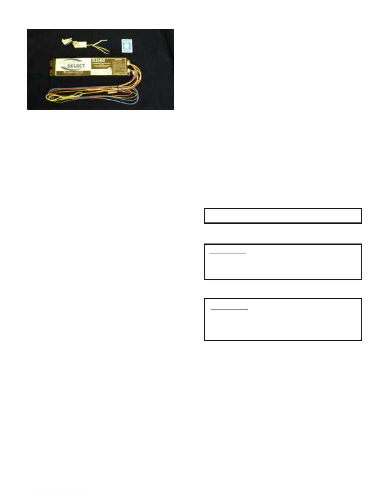
FIELD INSTALLABLE FLUORESCENT BATTERY
PACKISUNIVERSALLYCOMPATIBLEWITHTHE
BALLASTSANDOPERATINGLAMP(S)INTHE
LAMP COMPATIBILITY TABLE (PAGE 3).
IMPORTANTNOTES:
Make sure that branch circuit feeds are derived from
a common phase for both normal lighting ballast and
Battery Pack prior to installation.
Notice: To ensure proper grounding, mount unit only
with metal cutting screws (not provided).
The Battery Pack can be used with a switched or
unswitched (night) circuit. When used with a switched
fixture it is important to note that the power to the
Battery Pack must be provided by an unswitched
circuit.
EMERGENCYFLUORESCENTBATTERYPACK
ModelEI500

INSTALLATION
1. Turn off AC Power. Inspect Battery Pack and make sure
the Battery Connector eis disconnected. If still
connected, disconnect before installation.
2. Position unit in fixture wireway and fasten securely
through keyed slots or Mounting Holes or Slots b. If
necessary, drill holes and mount with metal cutting
screws (not provided).
3. Refer to appropriate wiring diagram. Connect unit to
ballast and lamp(s) and A.C. power leads as indicated in
appropriate wiring diagram.
aHOUSING
bMOUNTINGHOLES or SLOTS
c TEST SWITCH & PILOT LIGHT
d CHARGEINDICATOR LABEL
eBATTERYCONNECTOR
PARTS DESCRIPTION
FIGURE 1
TEST SWITCH/PILOT LIGHT (TS/PL)
INSTALLATION
CAUTION:
Do not locate Test Switch/Pilot Light cor route cable within
1” of fixture lamps.
NOTE: If pilot light is not visible outside the fixture lens, there
is a charge indicator label dlocated in pre-pack that should
be placed on the flat side of the lens directly below the test
switch and pilot light to identify it as an emergency fixture.
Page2
NOTE: Allow battery to charge 24 hours before initial testing
and 72 hours to fully charge battery.
NOTE:
Emergency lighting systems should be tested as often
as local codes require, or at least quarterly to insure that all
components are operational. Perform all test required by local
codes.
1. Check equipment rating to be sure that fixture will receive
proper line voltage.
2. Be sure pilot light is on. If pilot light does not operate,
check to see that:
A. Pilot Light Connector and test switch care con-
nected.
B. AC power is on.
C. Voltage on branch circuit to Battery Pack is rated
at line voltage (120V or 277V). If no line voltage can be
measured, locate problem in branch circuit and correct.
3. Press test switch. The pilot light cshould be off. One
fluorescent lamp should be operating at a reduced light
output.
INSPECTION AND MAINTENANCE
NOTE: Battery packs are not field serviceable units.
CAUTION:
Damage to battery will occur if Battery connection is made
for a prolonged period of time without AC power provided.
CAUTION:
Connecting the Battery Connector ealso connects the
battery to the inverter circuit which can result in high
voltage being present between the output leads.
1. Drill or punch one 1/2” holes in fixture wall or
wireway cover.
2. Insert one side of test switch/pilot light c into the
hold from the back and snap in the other side. Slide
mounting clip firmly onto mounting post to secure
test switch assembly.Mark the test switch location
with the charge indicator label.
3. Connect test switch and pilot light c leads to
violet and grey leads on inverter.See wiring
diagram for proper connections.
4. Apply continuous power to Battery Pack.
5. Connect the battery connector e(brown leads)
c d
a
be

FIGURE A
ONE LAMP RAPID START BALLAST
WIRING DIAGRAMS
IMPORTANT NOTES: BeforeconnectingTS/PL connectoror wiring unitto fixture,referto INSTALLATION PROCEDURE
and IMPORTANT SAFEGUARDS forsafetyinformation andmounting procedures.
Page3
TWO LAMP RAPID START BALLAST
FIGURE B
ONE LAMP INSTANT START SLIMLINE BALLAST
FIGURE C

Page4
TWO LAMP LEAD/LAG INSTANT START SLIMLINE BALLAST
FIGURE D
TWO LAMP SERIES LEAD BALLAST
TWO LAMP INSTANT START BALLAST
FIGURE F
FIGURE E

FIGURE G
Page5
THREE LAMP RAPID START BALLAST
THREE LAMP INSTANT START BALLAST
FIGURE H
ONE LAMP WITHOUT AC BALLAST
FIGURE I

Page6
ONE LAMP INSTANT START BALLAST
FIGURE J
ONE LAMP CIRCLINE BALLAST
FIGURE K
FOUR LAMP INSTANT START ELECTRONIC BALLAST
FIGURE L

Page7
TWO LAMP SERIES SEQUENCE INSTANT START BALLAST
FIGURE M
FOUR LAMP RAPID START BALLAST
Partno.EMCSA00742
REV C
FIGURE N
WARRANTY
ONE-YEAR WARRANTY
This fixture is guaranteed to perform for a period of one year from date of invoice. Our guarantee covers any
defect in manufacturing, provided the defect develops under normal and proper use. This liability does not
include lamps, and extends only to repair or replacement of the defective part and labor charges for correction
of the defect by repair or replacement. These labor charges will be paid by Lithonia Lighting only with prior
written authority has been granted by our Post Sales department.

Page8
Table of contents
Popular Batteries Pack manuals by other brands

GreenWorks
GreenWorks BAG711 Operator's manual

Pacvac
Pacvac SP700BC Product & training manual

Bowens
Bowens BW7635 user guide

ESY Sunhome
ESY Sunhome ESYSUNHOME 5KWH+ User guide & installation manual

MG Energy Systems
MG Energy Systems LFP Series manual

milleteknik
milleteknik NEO 24V 15A-25A FLX L PRO1 manual