LIW LORI User manual

USER MANUAL
LORI Stander
edition 2 –2020.06.09

page 2 LORI Stander edition 2
CAUTION! THE MANUFACTURER IS ONLY RESPONSIBLE FOR THE PRODUCT
PURCHASED DIRECTLY FROM THE LOCAL REPRESENTATIVE OF LIW CARE TECHNOLOGY
OR IN A SPECIALISED MEDICAL STORE REPRESENTING LIW CARE TECHNOLOGY WITHIN
THE TERRITORY OF POLAND.
CAUTION! THIS PRODUCT CAN ONLY BE USED INDOORS.
CAUTION! THERE MAY BE A RISK OF TRAPPING AND/OR SQUEEZING PARTS OF THE
BODY OF THE USER / ACCOMPANYING PERSON IN THE OPENINGS / SLOTS BETWEEN
THE ELEMENTS WHEN USING THE PRODUCT, AS WELL AS WHEN ASSEMBLING AND
ADJUSTING THE MECHANISMS. THESE PROCEDURES SHOULD BE PERFORMED WITH
PARTICULAR CAUTION. WHEN ALL THE ADJUSTMENTS HAVE BEEN PERFORMED, IT IS
CRUCIAL TO STABILISE THE POSITION BY PROPERLY TURNING THE NUTS / SCREWS.
CAUTION! IF POSSIBLE, THE PACKAGING OF THE PRODUCT SHOULD BE MAINTAINED
IN CASE THE PRODUCT NEEDS TO BE TRANSPORTED AGAIN IN THE EVENT OF
WARRANTY REPAIR.
CAUTION! THE CHILD MUST NOT USE THE DEVICE WITHOUT SUPERVISION.
CAUTION! THE MAXIMUM LOAD OF THE STANDER MUST NOT BE EXCEEDED.
CAUTION! DO NOT USE THE STANDER IF THE PRODUCT HAS DEFECTIVE, DAMAGED OR
MISSING COMPONENTS.
CAUTION! ADJUSTMENT AND REGULATION OF THE DEVICE TO MEET THE
REQUIREMENTS OF AN INDIVIDUAL PATIENT MUST BE PERFORMED BY A
PHYSIOTHERAPY SPECIALIST OR A TRAINED PERSON.
CAUTION! IT IS NECESSARY TO CAREFULLY READ THE USER MANUAL BEFORE USING
THE DEVICE.

LORI Stander edition 2 page 3
1. Introduction....................................................................................................................................................................... 3
General safety conditions........................................................................................................................................... 3
2. Identification of symbols.................................................................................................................................................... 4
3. Compliance with requirements concerning medical devices............................................................................................. 4
4. Indications for using the device ......................................................................................................................................... 4
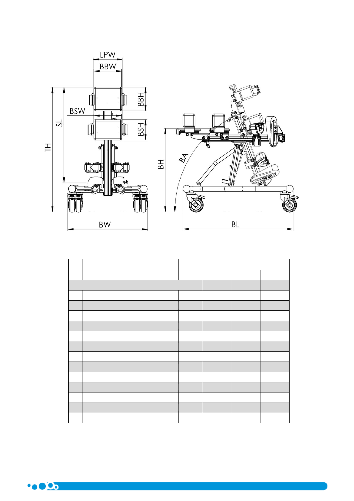
5. Technical data.................................................................................................................................................................... 5
6. LORI Stander –design........................................................................................................................................................ 6
7. Detailed description of the construction and adjustments of the LORI Stander ............................................................... 7
Assembly of the stander............................................................................................................................................. 7
7.1.1. Disassembly of the frame..................................................................................................................................... 7
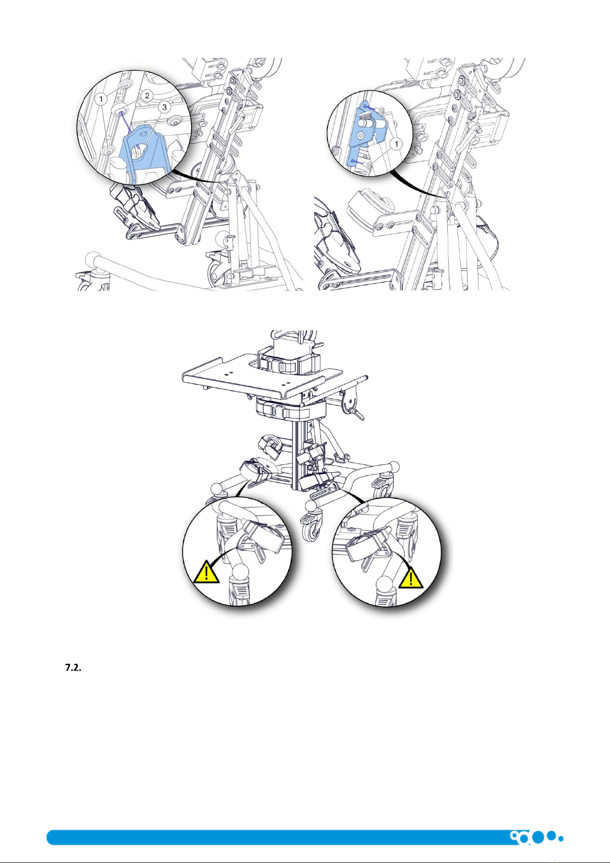
7.1.2. Installation of the column - Figures 4 and 5 ......................................................................................................... 7
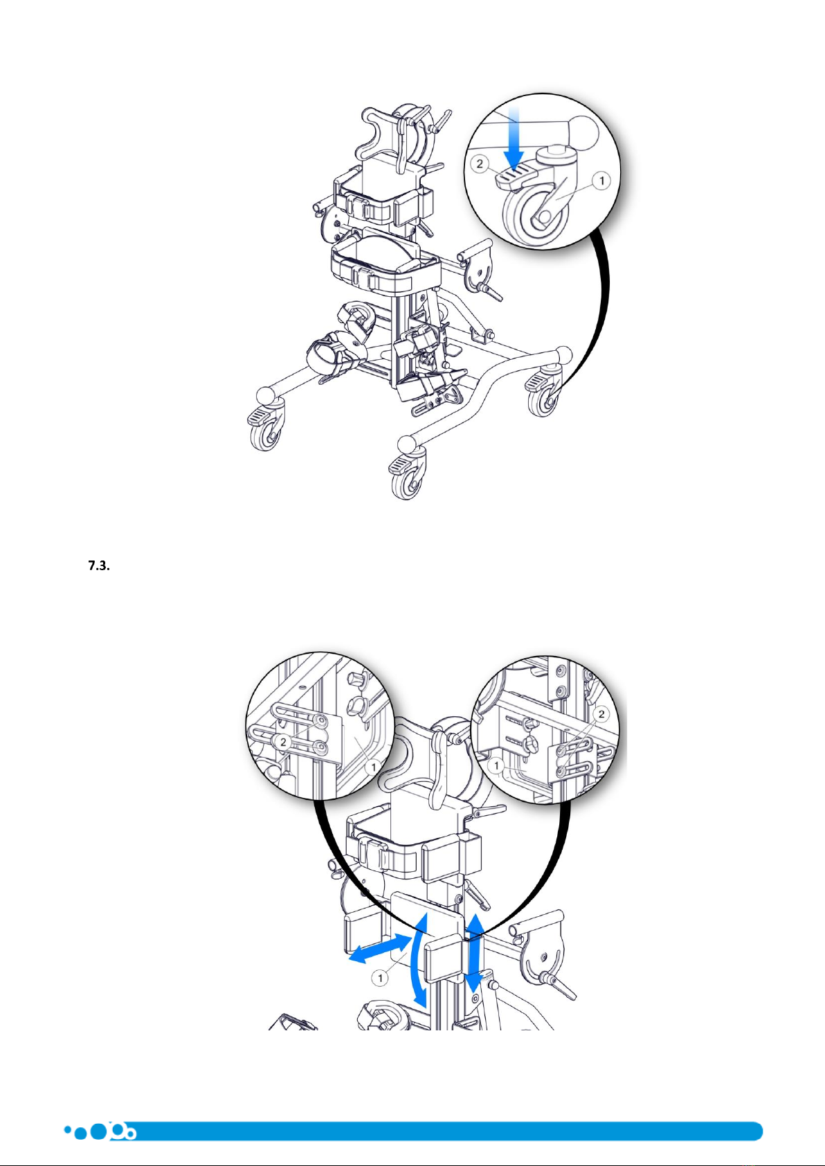
Wheels –Figure 6 ....................................................................................................................................................... 8
Main Hip support –Figure 7 ....................................................................................................................................... 9
Lateral support –Figure 8......................................................................................................................................... 10
Adjustment of chest and hip supports –Figure 9..................................................................................................... 10
Chest strap –Figure 10............................................................................................................................................. 11
Knee pads –Figure 11............................................................................................................................................... 11
Foot platforms.......................................................................................................................................................... 12
7.8.1. Adjustment of height and tilt of foot platforms - Figure 12 ............................................................................... 12
7.8.2. Adjusting the spacing and inclination of the foot platforms .............................................................................. 12
7.8.3. Adjustment (front-back) and rotation of the foot platform - Figure 14 ............................................................. 13
7.8.4. Installation of platforms in forward and reverse vertical position ..................................................................... 13
Vertical position –Figure 16..................................................................................................................................... 14
8. Accessories....................................................................................................................................................................... 15
Table......................................................................................................................................................................... 15
8.1.1. Adjustment of the table tilt angle –Figure 17.................................................................................................... 15
Headrest –Figures 19 and 20 ................................................................................................................................... 16
Corrective hip strap - Figures 21 and 22................................................................................................................... 17
Shoulder protectors –Figure 23 ............................................................................................................................... 18
Fastened SideUP chest supports –Figure 24............................................................................................................ 18
9. Cleaning and maintenance .............................................................................................................................................. 19
Recommendations for cleaning and maintenance ................................................................................................... 19
Disinfection............................................................................................................................................................... 19
10. Nameplate ....................................................................................................................................................................... 20
11. Warranty/Service............................................................................................................................................................. 20
1. Introduction
The LORI Stander developed by LIW Care Technology Sp. z o.o. has been designed and patented to ensure an entirely new
quality in rehabilitation.
We have used our best efforts to make sure that the LORI Stander is as easy to use as possible. It is necessary to read the user
manual carefully prior to using the product. Following all instructions and recommendations included in this user manual will allow
you to avoid any situations which could damage the device, and you will also ensure the complete safety and comfort of use
throughout the whole period of using the product.
You will be able to fully use all the advantages offered by the product only when it is properly adjusted to the parameters of
the patient's body and the specific requirements of the patient.
General safety conditions
The biggest concern of LIW Care Technology Sp. z o.o. is to ensure safety for the patients using our devices. In order to provide
complete safety of the persons using the device, it is essential to strictly follow the recommendations stated below:
1. Before undertaking any attempts to use the device, please read the user manual thoroughly and in case of any doubts,
do not hesitate to contact the seller or the manufacturer.
2. Please make sure that all the information, recommendations and cautions included in these chapters are fully
comprehensible.
The user manuals attached to devices manufactured by LIW Care Technology Sp. z o.o. include paragraphs marked with the
word CAUTION, intended to emphasise the content of the given paragraph. The significance of the above-mentioned symbol is as
follows:
CAUTION!

page 4 LORI Stander edition 2
CAUTION! THIS SYMBOL IS USED TO STRENGTHEN THE FOCUS OF THE READER ON THE
CONTENT MARKED WITH THIS SYMBOL. FAILURE TO COMPLY WITH THE CONTENT
UNDER THIS SYMBOL MAY ENDANGER THE LIFE OR HEALTH OF THE USER.
2. Identification of symbols
Manufacturer name and production date
Serial number
Permitted user weight
Avoid contact with water
Follow the user manual
The arrow indicates the discussed element
Arrows indicating the direction of movement
Conformity marking according to the Council Directive
93/42/EEC concerning medical devices, annex VII
3. Compliance with requirements concerning medical devices
LORI Stander device meets the essential requirements of the MDD Directive 93/42/EEC for medical devices.
According to annex IX to the MDD Directive 93/42/EEC, the LORI Stander device is classified as a non-invasive, active class I
medical device in accordance with rule 1.
Conformity declaration of the device can be obtained in the Sales Department of the manufacturer.
CAUTION! In case of any modification of the device, the use of non-original spare parts
or use with products of another manufacturer, the CE marking must be removed.
4. Indications for using the device
LORI Stander can be used in persons with posture defects and muscle dysfunction. It is the perfect solution for children
suffering from cerebral palsy, muscular dystrophy, in various types of paralyses, tetraplegias and paraplegias, as well as for children
with posture disorders. This device may also be used for therapeutic and prophylactic reasons, as it can prevent the inevitable
consequences of paediatric diseases (incorrect posture and related disorders).
Obtaining a vertical position allows to improve the functioning of patient’s systems and organs, in particular:
−cardiovascular system,
−respiratory system,
−digestive system,
−skeletal system.
Using the device during the rehabilitation process of the patient increases the chances of recovery.

LORI Stander edition 2 page 5
5. Technical data
Figure 1
No.
Dimensions
Symbol
Size [cm]
1
2
3
Baby
Junior
Teen
1
Base width
BW
63
63
70
2
Base length
BL
78
78
105
3
Total height (without headrest)
TH
90
115
147
4
Platform height
BH
60
75
90
5
Platform length
SL
43 ÷ 68
57 ÷ 98
80 ÷ 130
6
Pivot angle range
BA
90° ÷ -15°
90° ÷ -15°
90° ÷ -15°
7
Hip/lateral support spacing
LPW
12 ÷ 20
17 ÷ 25
19 ÷ 29
8
Hip support height
BSH
15
20
24
9
Hip support width
BSW
20
25
28
10
Chest support height
BBH
18
23
27
11
Chest support width
BBW
20
25
28
12
Maximum user weight
35 kg
50 kg
60 kg
13
Total device weight
20 kg
22kg
25kg

page 6 LORI Stander edition 2
6. LORI Stander –design
Figure 2
1. Standing frame
2. Wheels
3. Foot platform
4. Knee pad
5. Vertical position release handle
6. Chest support
7. Headrest
8. Main hip support
9. Main chest support
10. Hip support
11. Table support
12. Chest belt
13. Hip belt
14. Column

LORI Stander edition 2 page 7
7. Detailed description of the construction and adjustments of the LORI Stander
CAUTION! After each adjustment, it is crucial to make sure that all assembled and
adjusted elements are properly mounted and secured.
Assembly of the stander
CAUTION! When assembling the frame, special attention should be paid to the
possibility of limbs being trapped by moving parts.
CAUTION! After assembly of the device, make sure that all adjusting screws are tight.
Loose components may cause the adjustable components to move automatically, which
may result in patient injury.
The Stander is delivered in two parts: standing frame and column. In order to assemble the standing
frame, perform the following actions:
7.1.1. Disassembly of the frame
To disassemble the frame, first unscrew the screws (1), then set the frame support (2) in the correct position. After setting
the frame support, the previously unscrewed screws (1) should be screwed to the frame through the support openings.
Figure 3
7.1.2. Installation of the column - Figures 4 and 5
To install the column on the standing frame, first unscrew the screws (1) and then place the pin (2) in the opening of the
system profile holder (3). When aligning the column, make sure that the distance between the foot platform supports and the
frame profiles (see Fig. 5.) is even. The last step of the installation is tightening the frame to the column with the previously
unscrewed screws (1).

page 8 LORI Stander edition 2
Figure. 4
Figure 5
Wheels –Figure 6
The support frame of the stander is equipped with a set of wheels allowing to move the device indoors. In order to ensure
the safety of the patient, each wheel is equipped with brakes blocking the movement of the wheel. Due to safety reasons, the
wheels should be blocked when using and adjusting the device. When moving the device, special caution must be taken when
moving through door thresholds or other obstacles.
To lock the wheel brake (1), press the brake lever (2) into the lower position. To unlock the brake, pull the same lever upwards.

LORI Stander edition 2 page 9
Figure 6
Main Hip support –Figure 7
The hip support is the main support for the patient. For accurate adjustment to the patient, adjust the position of the support
(1) by loosening the screws (2). The hip support can be adjusted in 3 directions: top-down, depth and angled in the lateral plane.
Once in the desired position, retighten the screws (2).
Figure 7

page 10 LORI Stander edition 2
Lateral support –Figure 8
Lateral support is used to support the patient at chest height. To accurately adjust the height to the patient, adjust the position
of the support (1) by loosening the screws (2). The chest support can also be adjusted in terms of support depth and angle in the
lateral plane. To adjust the depth of the support, loosen the screws (3). Once in the desired position, retighten the screws (2) and
(3).
Figure 8
Adjustment of chest and hip supports –Figure 9
Both chest and hip supports ensure patient stability. The supports are mounted independently which makes it possible to set
each support separately.
To adjust the width of the support, loosen the knob (2) (it is not necessary to unscrew it completely) and set the supports in
the desired position. After completing the adjustment of the support’s position (1), tighten the knob (2) until you feel resistance.
Figure 9

LORI Stander edition 2 page 11
Chest strap –Figure 10
The chest strap allows for stable patient support at chest height. To release and fasten the belt buckle (1), use the lock button
(2) on the upper part of the buckle.
Figure 10
Knee pads –Figure 11
Adjust the knee pad setting (1) by loosening the screws (3) and then moving the knee pad holder (2) to the desired position.
Horizontal position and knee pad rotation (3) can be set after loosening the screws (4). After completing the adjustment, tighten
all screws.
Adjustment should be carried out for each knee support separately.
CAUTION! After each adjustment of the kneepad, make sure that all adjustment screws
are securely tightened. Unscrewed elements may cause the adjustable elements to shift
automatically, which may result in injury to the patient.
Figure 11

page 12 LORI Stander edition 2
Foot platforms
The foot platforms used in the stander are fully adjustable in three planes. The tilt angle of the platform is also adjustable. In
order to ensure the most precise adjustment to the patient's needs, each platform is adjusted separately.
CAUTION! After each adjustment of the foot platform, make sure that all adjustment
screws are securely tightened. Unscrewed elements may cause the adjustable elements
to shift automatically, which may result in injury to the patient.
7.8.1. Adjustment of height and tilt of foot platforms - Figure 12
The foot platforms used in the stander enable full adjustment of the patient's foot position. To adjust the height and angle of
the foot platform, loosen the screws (2). Then move the platform support (1) along the guide of the stander column. Once the
desired position is reached, lock the platform position by tightening the screws (2).
Figure 12
7.8.2. Adjusting the spacing and inclination of the foot platforms
The horizontal position of the foot platform and its tilt can be adjusted after loosening the screws (2). The adjustment allows
the foot platform to be moved along the support (1). After completing the adjustment of the platform position, tighten the screws
(2). To adjust the right and left platform spacing equally, pay attention to the ruler (1). The indicator (3) must show the same values
on the ruler on the right and left.
Figure 13

LORI Stander edition 2 page 13
7.8.3. Adjustment (front-back) and rotation of the foot platform - Figure 14
Adjustment (front-back) and rotation of the foot platform is possible after loosening the screws (2) and (3). The adjustment
allows the foot platform to be moved in the (front-back) direction. After completing the adjustment of the platform, tighten the
screws (2) and (3).
Figure 14
7.8.4. Installation of platforms in forward and reverse vertical position
The stander allows to assume forward and reverse vertical position. To achieve the appropriate type of vertical position, the
footrest platforms should be installed in the appropriate direction. To change the direction of the footrest platforms (4), remove
the screw (2) and loosen the screw (1) from the locking plate (3), then rotate the platforms 180 degrees. In the next step, screw in
the screw (2) and tighten the screw (1).
Figure 15

page 14 LORI Stander edition 2
Vertical position –Figure 16
The patient should always be placed in vertical position with the base wheel brakes locked. The brakes prevent
accidental shifting of the device, which could cause uncontrolled repositioning and injury to the patient. The change
of position (verticalisation) is supported by the gas spring force. When changing position, it is necessary to fully control
and limit the automatic movement of the device by holding the device by hip or chest support.
To change the patient's verticalisation angle, press the release pedal (1) with your leg to release the spring and
adjust the position. When performing the adjustment, pay particular attention to the area between the column, base
and footrest supports. No objects should be located there, as they may block the movement of the device, resulting
in damage to the device or trapping and injuring the patient or the device operator. To lock the adjustment, release
the pedal (1), which will lock the gas spring and immobilize it in position.
CAUTION! When adjusting the verticalisation angle, special attention should be paid to
the possibility of limbs being trapped by moving parts.
CAUTION! After each adjustment of the verticalisation angle, make sure that the gas
spring is locked and that the hip and chest support position does not shift automatically.
CAUTION! When placing the patient in a vertical position, the device's wheel brakes
should be locked. Uncontrolled movement of the device may cause injury or trauma to
the patient.
Figure 16

LORI Stander edition 2 page 15
8. Accessories
Table
8.1.1. Adjustment of the table tilt angle –Figure 17
To adjust the table tilt angle (1), loosen the screws (3) and the adjustment handles (2). Once the angle has been set, tighten
the knobs (2) and screws (3) to lock the tabletop in position.
Figure 17
Adjustment of the height and the front-back position of the table - Figure 18
To adjust the front-back position of the table, loosen the knob (4), which allows you to move the arms (3) of the table. The
height of the table is adjusted by loosening the screws (2), which makes it possible to move the entire table structure in the vertical
axis.
Figure 18
CAUTION! When disassembling the table, it is essential to secure the table guides with
plugs.

page 16 LORI Stander edition 2
Headrest –Figures 19 and 20
To install the headrest, insert the headrest holder rod (1) into the opening in the upper part of the stander column. Then
adjust the height of the headrest and use the knob (2) to prevent the headrest from sliding out.
CAUTION! After each adjustment of the headrest, make sure that all adjusting elements
are securely tightened. Unscrewed elements may cause the adjustable elements to shift
automatically, which may result in injury to the patient.
Figure 19
To adjust the headrest (1), loosen the adjusting knobs (2), move the headrest to the desired position and tighten the knobs
(2).
Figure 20

LORI Stander edition 2 page 17
Corrective hip strap - Figures 21 and 22
The corrective hip strap is an additional option allowing to stabilise the patient at hip height. To install the belt, remove the
hip supports (1) by loosening the knobs (2). Then use the knobs (2) to screw in the hip strap support (3).
Figure 21
Finally, pass the strap (4) through the slots in the corrective hip strap support (3). To release and fasten the belt buckle, press
the buckle locking button (5) on top of the buckle.
Figure 22

page 18 LORI Stander edition 2
Shoulder protectors –Figure 23
In the case of rear verticalisation, shoulder support is sometimes required for the safety and comfort of the user.
The Lori stander offers an accessory that makes this possible. To adjust the front angle, loosen the knobs (4), then set the
required angle and tighten the knobs when the adjustment is complete. To change the depth and tilt in the upper plane, loosen
the screws (3). After adjusting the angle and depth, tighten the screws (3).
Figure 23
Fastened SideUP chest supports –Figure 24
To release the support, press the red button of the buckle (see ), then lift the support (1) and tilt it. Proceed with the second
support in the same way. The tilted supports make it easier to place the patient in the device. To re-fasten the SideUP supports, tilt
them back until they snap back into their base position.
The SideUP supports can be adjusted in two directions by loosening the knob (2) and tightening the knobs (2) after adjustment (2)
Figure 24

LORI Stander edition 2 page 19
9. Cleaning and maintenance
LORI Stander is a mechanical device with a supporting structure made of steel and aluminium covered with a powder coating.
A sponge-foam insert is attached to the metal structure and fitted with a cover made of textile fabrics.
The LORI stander, like any medical device, should be kept clean and used according to the manufacturer's recommendations.
Recommendations for cleaning and maintenance
Clean paint coatings with a cloth dampened with water. The use of mild agents for cleaning household appliances is allowed.
Guidelines for upholstery washing:
•Remove sponge inserts from the covers before washing.
•The covers should be washed by hand or in an automatic (tumble) machine at 30 C.
•Use PZH-approved detergents for delicate products in quantities specified on the package.
•For children prone to allergies, use grey soap or special detergents.
•To remove excess water –use a short spin cycle, do not wring.
•Drying –hang to dry at room temperature. DO NOT TUMBLE DRY.
CAUTION! WHILE WASHING THE UPHOLSTERY COVERS, PARTICULAR ATTENTION
SHOULD BE PAID TO THE VELCRO FASTENERS. TO PREVENT ANY DAMAGE TO THE
UPHOLSTERY, ENSURE THE VELCRO FASTENERS ARE UNFASTENED DURING THE
WASHING AND THAT THEY DO NOT COME IN TO CONTACT WITH THE UPHOLSTERY.
CAUTION! Do not wash the foam inserts.
The sponge-foam insert:
•Should be vacuumed mechanically or cleaned using a soft-bristled brush.
•Can be washed with a damp cloth and a mild detergent, then dried thoroughly at room temperature.
Disinfection
If the device is used by different people (e.g. in a rehabilitation centre), disinfectants should be applied. For manual
disinfection of metal and plastic parts of the product, INCIDIN PLUS in a concentration of 0.25% to 0.5% or similar disinfectant is
recommended.
Please follow the manufacturer's instructions for use of the disinfectant.
CAUTION! The device should undergo maintenance, performed by a qualified service
technician, at least once a year (every 12 months). During maintenance, the safety of the
device should be checked - the condition of the movable connections, snap-in and
adjustment mechanisms should be checked. Periodic inspections of the device ensure
long-term and problem-free operation.
CAUTION! The device is not waterproof. Do not allow the device to come into direct
contact with water. Use the device indoors at room temperature. Do not expose the
device to direct contact with weather conditions.

page 20 LORI Stander edition 2
10. Nameplate
Figure 25
11. Warranty/Service
If any defects or damage are noticed, stop using the device immediately and contact the seller or manufacturer. Protect a
defective device to prevent the damaged area from expanding. Do not attempt to repair the unit yourself. Do not replace the
original parts of the device with parts made by yourself or obtained from other sources than recommended by the manufacturer.
•If the user decides to discontinue the operation of the device, he is obliged to dispose of it in accordance with
environmental regulations.
•The manufacturer determines the product life to be 5 years.
•The post-warranty service of the device is performed by the manufacturer.
Contact details of the service department:
LIW Care Technology Sp. z o.o., ul. Golfowa 7, 94-406 Łódź.
www.liwcare.pl
e-mail: reklamacje@liwcare.pl
•Current address details are available at www.liwcare.pl.
•Terms of the warranty have been specified in the warranty card which constitutes an integral part of this user manual
and is available on the last page.
Table of contents
Other LIW Medical Equipment manuals
Popular Medical Equipment manuals by other brands

Otto Bock
Otto Bock 12K27 Instructions for use

GENICON
GENICON REUSABLE MONOPOLAR X-SURGE SHAFT HANDLE Instructions for use

Proactive
Proactive alevia instructions

Dentsply Sirona
Dentsply Sirona Primescan AC Service manual

Fona
Fona XPan 3D operating instructions

Jorvet
Jorvet J0744emb Filter Changing Instructions