LIW COCO User manual

INSTRUCTIONS FOR USE
COCO Stander
COCO Stander edition 2 - 09.06.2020

page 2 COCO Stander edition 2
NOTE! THE MANUFACTURER IS ONLY RESPONSIBLE FOR THE PRODUCT PURCHASED
DIRECTLY FROM THE LOCAL REPRESENTATIVE OF THE LIW CARE TECHNOLOGY OR IN A
SPECIALISED MEDICAL STORE REPRESENTING LIW CARE TECHNOLOGY WITHIN THE
TERRITORY OF POLAND.
NOTE! THIS PRODUCT CAN ONLY BE USED INDOORS.
NOTE! THERE IS A POSSIBLE RISK THAT A PART OF THE USER'S / AN ACCOMPANYING
PERSON'S BODY MAY BE ENTRAPPED AND/OR SQUEEZED IN THE HOLES / GAPS
BETWEEN INDIVIDUAL ELEMENTS WHEN USING THE PRODUCT, AS WELL AS WHEN
ASSEMBLING AND ADJUSTING MECHANISMS OF THE PRODUCT. THESE PARTICULAR
PROCEDURES SHOULD BE PERFORMED WITH PECULIAR CAUTION. WHEN ALL THE
ADJUSTMENTS HAVE BEEN PERFORMED, IT IS CRUCIAL TO STABILISE THE POSITION BY
PROPERLY TURNING THE NUTS / SCREWS.
NOTE! IF POSSIBLE, THE PACKAGING OF THE PRODUCT SHOULD BE MAINTAINED IN
CASE WHEN IT WOULD PROVE NECESSARY TO SHIP THE PRODUCT WITHIN THE SCOPE
OF WARRANTY REPAIR.
NOTE! THE CHILD CANNOT USE THE DEVICE WITHOUT SUPERVISION.
NOTE! IT IS FORBIDDEN TO EXCEED THE MAXIMUM LOAD OF THE STANDER.
NOTE! DO NOT USE THE STANDER IN CASE WHEN THE PRODUCT HAS DEFECTIVE,
DAMAGED OR MISSING COMPONENTS.
NOTE! ADJUSTMENT AND REGULATION OF THE DEVICE TO MEET THE REQUIREMENTS
OF AN INDIVIDUAL PATIENT MUST BE PERFORMED BY A PHYSIOTHERAPY SPECIALIST
OR A TRAINED PERSON.
NOTE! IT IS CRUCIAL TO CAREFULLY READ THE USER MANUAL BEFORE USING THE
DEVICE.

COCO Stander edition 2 page 3
1Introduction....................................................................................................................................................................... 3
2Identification of symbols.................................................................................................................................................... 4
3Compliance with requirements concerning medical devices............................................................................................. 4
4Indications for using the device ......................................................................................................................................... 4
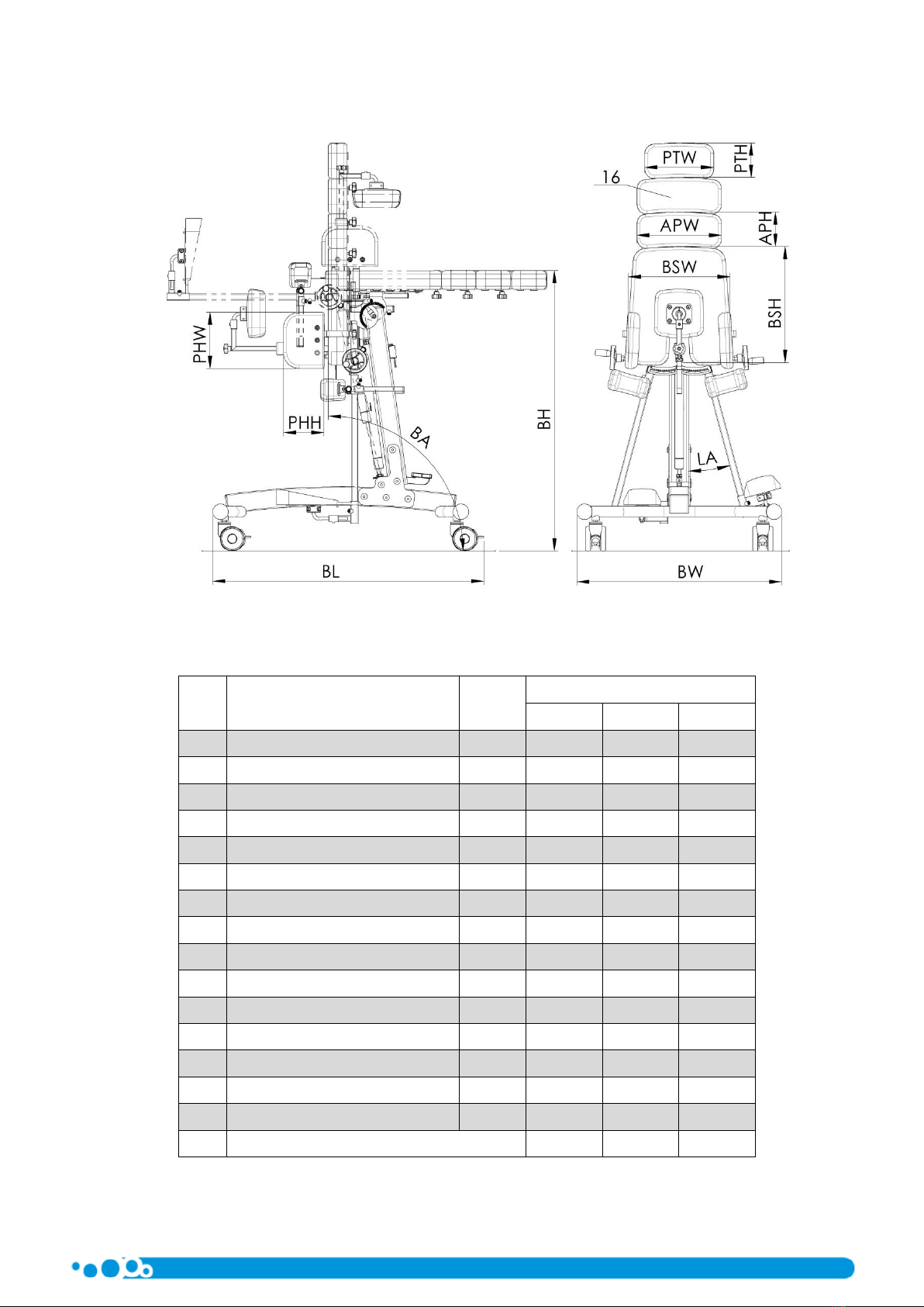
5Technical data.................................................................................................................................................................... 5
6Basic design of the COCO Stander ..................................................................................................................................... 6
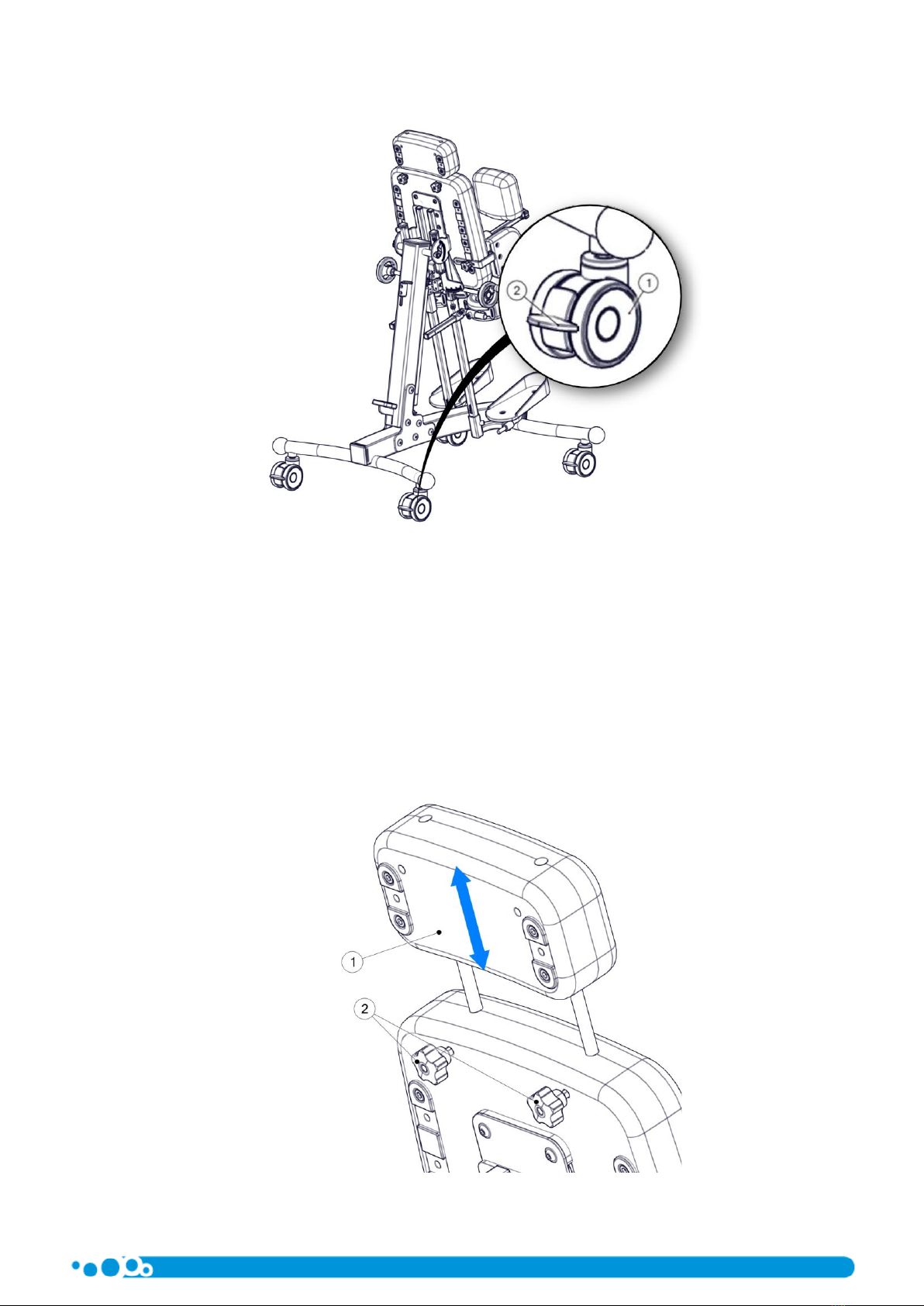
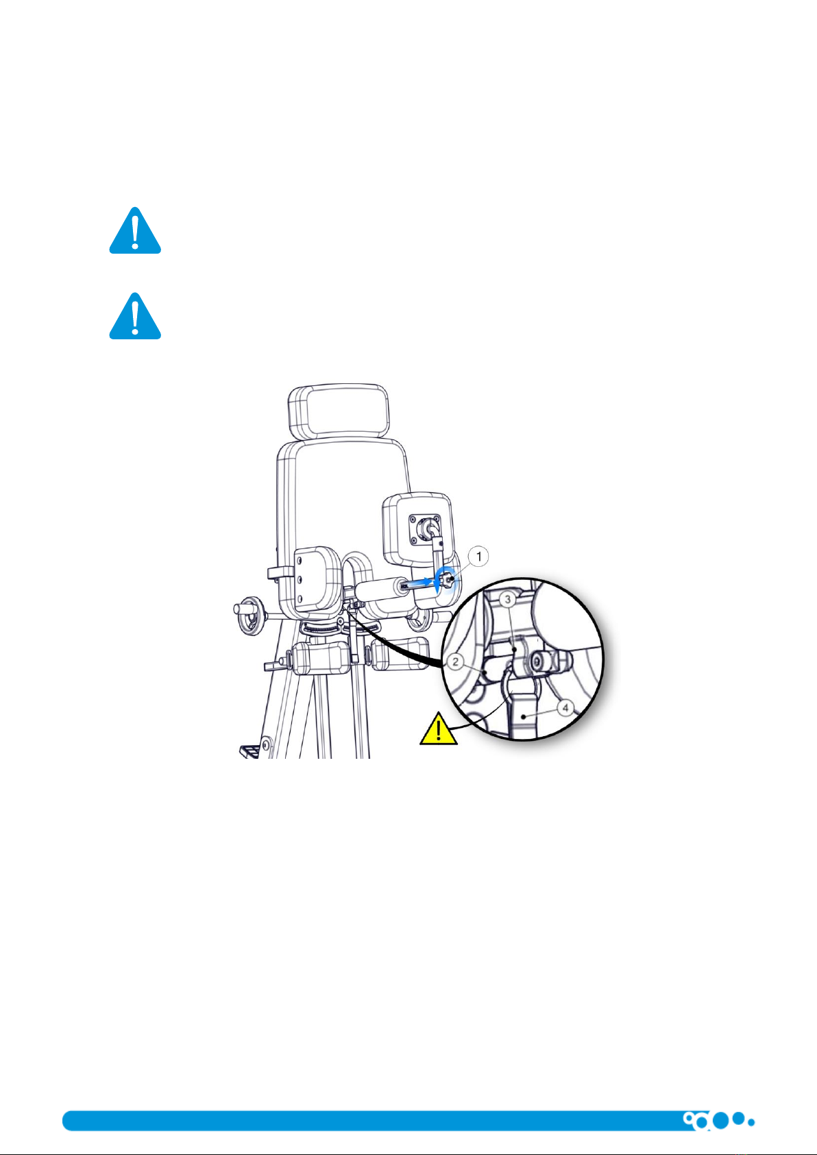
7Detailed description of the design and regulation of the COCO Stander........................................................................... 6
8Accessories....................................................................................................................................................................... 14
9Cleaning and maintenance .............................................................................................................................................. 19
10 Nameplate ....................................................................................................................................................................... 20
11 Warranty/Service............................................................................................................................................................. 21
1Introduction
The COCO Stander elaborated by LIW Care Technology Sp. z o.o. has been designed and patented to ensure an entirely new
quality in rehabilitation.
We have used our best efforts to make sure that the COCO Stander is easy to use and user-friendly. It is crucial to read the
user manual carefully prior to using the product. Following all instructions and recommendations stated in this user manual will
allow you to avoid any situations, which could possibly damage the device, and you will also ensure a complete safety and comfort
of use throughout the whole period of using the product.
You will be able to fully use all the advantages offered by the product only when the product is properly adjusted to the
parameters of the patient's body and the unique requirements of the patient.
1.1 General safety conditions
The biggest concern of LIW Care Technology Sp. z o.o. is to ensure safety for the patients using our devices. In order to provide
complete safety of people using the device it is essential to strictly follow the recommendations stated below:
1. Before undertaking any attempts related with using the device, please read the user manual thoroughly and in case of
any doubts, do not hesitate to contact the seller or the manufacturer.
2. Please make sure that all the information, recommendations and warning included in these chapter are fully
comprehensible.
User manual attached to devices manufactured by LIW Care Technology Sp. z o.o. holds a paragraph marked with a word
NOTE, which aims to emphasise the content of the given paragraph. The significance of the symbol, of which mention has been
made above is as follows:
NOTE!
NOTE! THIS PARTICULAR SYMBOL IS USED TO STRONGLY EMPHASISE THE FOCUS OF
THE READER ON THE WORDING MARKED WITH THIS SYMBOL. NON-COMPLIANCE
WITH THE CONTENT PROVIDED IN THE PARAGRAPH MARKED WITH THIS SYMBOL MAY
ENDANGER THE LIFE OR HEALTH OF THE USER.

page 4 COCO Stander edition 2
2Identification of symbols
Name of the manufacturer and production date
Serial number
Permitted user's weight
Avoid contact with water
Follow the user manual
The arrow indicates the discussed element
Arrows indicating the direction of movement
Conformity marking according to the Council Directive
93/42/EEC concerning medical devices, annex VII
3Compliance with requirements concerning medical devices
COCO Stander device meets the essential requirements of the MDD Directive 93/42/EEC for medical devices.
According to annex IX of the MDD Directive 93/42/EEC the COCO Stander device is classified as a non-invasive, active medical
device class I in accordance with rule 1.
Conformity declaration of the device can be obtained in the Commercial Department of the manufacturer.
NOTE! In case of introducing any modifications to the device, using non-original spare
parts or utilizing with products provided by another manufacturer, the CE marking has to
be removed.
4Indications for using the device
COCO Stander can be used in people with faulty posture and muscle dysfunction. It is a perfect solution for children suffering
from cerebral palsy, muscular dystrophy, in various types of paralyses, tetraplegias and paraplegias, as well as in children with
incorrect posture. This device may also be used for therapeutic and prophylactic reasons, as it can prevent inevitable consequences
resulting from paediatric diseases (incorrect posture and an improper functioning of the organism related with the above).
Obtaining a supine position allows to improve functioning of various systems and organs in the patient's body, and in
particular:
−cardiovascular system,
−respiratory system,
−digestive system,
−skeletal system.
Implementing the device during the rehabilitation process of the patient increases the chances of recovery.

COCO Stander edition 2 page 5
5Technical data
Fig. 1
No.
Dimension name
Symbol
Size
1
2
3
1
Base width
BW
66 cm
66 cm
66 cm
2
Base length
BL
82 cm
82 cm
82 cm
3
Platform height
BH
93 cm
93 cm
93 cm
4
Pivot angle range
BA
90° ÷ -15°
90° ÷ -15°
90° ÷ -15°
5
Abduction angle
LA
0° ÷ 30°
0° ÷ 30°
0° ÷ 30°
6
Main trunk support height
BSH
30 cm
38 cm
43.5 cm
7
Main trunk support width
BSW
28 cm
32.5 cm
38 cm
8
Trunk support height
PTH
11 cm
11 cm
11 cm
9
Trunk support width
PTW
17 cm
22 cm
27 cm
10
Extra trunk support height
APH
11 cm
11 cm
11 cm
11
Extra trunk support width
APW
22 cm
27 cm
31.5 cm
12
Hip support height
PHH
13 cm
13 cm
13 cm
13
Hip support width
PHW
13 cm
18 cm
18 cm
14
Maximum user’s weight
60 kg
60 kg
60 kg
15
Total standing frame’s weight
38.5 kg
39 kg
40 kg
16
Extra trunk support –max 2 units per stander

page 6 COCO Stander edition 2
6Basic design of the COCO Stander
Fig. 2
1. Standing frame
2. Wheels
3. Main trunk support
4. Back support
5. Knee support
6. Foot platform
7. Extra support
8. Hip support
9. Supine position releasing handle
10. Abduction regulator
7Detailed description of the design and regulation of the COCO Stander
NOTE! After each adjusting procedure, it is crucial to make sure that all regulated
elements are properly mounted and secured.
7.1 Wheels
The standing frame of the stander is equipped with a set of wheels enabling transporting of the device indoors. In order to
ensure safety of the patient, each of these wheels is equipped with breaks blocking the movement of the wheel. Due to safety
reasons the wheels should be blocked when using and regulating the device. When transporting the device, it is crucial to be
particularly careful when moving through door thresholds or other obstacles.
In order to block the brake of a wheel (1), push the handle of the break (2) down. In order to unblock the break, pull the same
handle upwards.

COCO Stander edition 2 page 7
Fig. 3
7.2 Main trunk support
Main trunk support constitutes the basic support of the patient. In order to perfectly adjust the device to the patient's body,
it is essential to adjust the location of the extra support, back support and hip support.
7.2.1 Regulation of the extra support
The extra support added to the main trunk support enables adjusting the length of the head support to the required
dimension. In order to regulate the position of the extra support (1), undo the knobs (2) and then set the required height. When
the extra support is in a proper position, tighten the knobs (2) in order to block the possibility of any movement of the extra support.
Fig. 4

page 8 COCO Stander edition 2
7.2.2 Regulation of the back support
Before placing the patient in the device, it is essential to disassemble the back support. In order to do so, undo the knob (1)
and remove the back support. The next step is to fold the blockade of the back support bracket (2) and take it out of the clamp (3)
by pulling it away with the belt (4).
NOTE! Pay particular attention and verify that the blockade of the back support bracket
is properly seated in the clamp. Imprecise placement of the blockade in the clamp may
result in autonomous release of the blockade, which in consequence may cause folding
of the back support and hence the lost of stability by the patient. This may cause serious
harm to the patient.
NOTE! When adjusting, taking out or blocking the bracket of the back support, be
particularly aware of the risk and pay particular attention to the fact that hands may be
trapped by the moving components.
Fig. 5
After placing the patient in the device we put the back support bracket and secure it. Back support enables accurate regulation
within all planes. Back support adjustment is shown in Fig. 6. After setting the depth of back support, tighten the knob (1) and
hence block the possibility to remove the back support. Maximum possible distance of the depth is marked with the "MAX" mark.
The height of the attachment is regulated by undoing the screw (2). After setting the height of the back support, we block it by
tightening the screw (2) until resistance. Accurate adjustment of the position of the back support cushion can be obtained by
loosening the screws (3), and then by adjusting the back support and finally retightening the screw (3).

COCO Stander edition 2 page 9
Fig. 6
7.2.3 Regulation of the hip support.
Hip support ensure proper stabilisation of the patient. Regulation of the hip support location is possible both as far as width
and height is concerned. Hip supports are assembled independently, and this allows to adjust each hip support individually. In order
to set the height of the hip support (1) undo the knob (2) and then select one of the slots in the guiding profile (3). After setting the
hip support inside the slot in the profile, tighten the knob (2) and hence attach the hip support to the guiding profile.
Fig. 7

page 10 COCO Stander edition 2
Adjustment focusing on the width of the hip support is performed by loosening the knob (2) (there is no need to entirely undo
the knob), and the second step comes down to setting the location of the hip support (1) and retightening the knob (2).
Fig. 8
Additional regulation of the hip support.
Construction of the hip support enables an additional height regulation within the scope of mounting in one slot of the guiding
rail (2). In order to implement this adjustment, it is essential to unscrew all screws (3) and then move the hip support into the
second slot taking advantage of the remaining assembly holes in the hip support. After moving the hip support, tighten the screws
(3) in the new location.
Fig. 9

COCO Stander edition 2 page 11
7.3 Knee support
The position of knee support can be adjusted by loosening the screw (2) and the by shifting the handle of the knee support
along the vertical rail. Retightening the screw (2) blocks the position of the support. Adjustment of the depth of the knee support
can be done by loosening the screw (1) and then finding the proper location by shifting the arm of the knee support. We block any
possibility of further movement by tightening the screw (1). It is worth remembering not to extend the arm of the knee support
outside the marker indicating the position of the maximal extension. Precise setting of the width and angle of the knee support
may be adjusted after loosening the screw (3) and (4). When the whole regulation process is finished, we tighten the screw and by
the same we block the possibility of any movement, as far as knee support is concerned.
Adjustment procedures should be performed individually for each of the knee supports.
NOTE! Make sure that all regulating screws are properly tightened after each and every
adjustment of the knee support. Loose elements may result in autonomous shift of the
regulated elements and this may cause injuries of the patient.
Fig. 10
7.4 Feet platforms
Feet platforms in this stander provide the possibility to regulate their height, depth, width, as well as inclination angle of each
platform. Each foot platform is regulated independently in order to ensure the most accurate adjustment as far as the requirements
of the patient are concerned.
NOTE! When regulating the height of the feet platforms make sure that the maximum
extension of the platform has not been exceeded. The maximal extension of the
platform is marked with a "MAX" mark indicated on the rail. Placing the platform
outside the indicated scope may result in autonomous shift of the foot platform, which
in consequence can cause patient's injuries.
NOTE! After each regulation of the foot platform it is crucial to make sure that all
regulating screws are properly tightened. Loose element may result in autonomous shift
of the regulated element, which can cause patient's injuries.

page 12 COCO Stander edition 2
7.4.1 Regulation of the height and depth of feet platforms
Feet platforms in the stander provide a complete regulation of the patient's feet. In order to adjust the height of the platform,
loosen a screw (3) and then shift the corpus (1) of the foot platform along the rail. When regulating the position of the foot platform
it is crucial to pay special attention not to extend the foot platform past the MAX mark. In order to block the position of the platform,
tighten the screw (3) and hence block the possibility of the foot platform to move. Regulation of the depth of the foot platform is
possible after loosening the screw (4), which enables shifting the arm (2) of the foot platform. Retighten the screw (4) to block the
location of the foot platform. When adjusting the foot platform, make sure that the screw (4) stays in the groove guiding the arm
of the platform. This guarantees the safe scope of the platform's location.
Final feet platform adjustment is possible after loosening the screws (5). Move platforms and tighten the screw (5).
Fig. 11
7.4.2 Regulation of the inclination angle of the foot platform
In order to adjust the angle of the inclination of the foot platform (1) it is necessary to loosen the screws (2) of the platform's
clamps. After setting the demanded angle, tighten the screw and hence block the rotation of the platform. This adjustment
procedure should be performed independently for each of the foot platforms.
Fig. 12

COCO Stander edition 2 page 13
7.5 Supine position
Placing the patient in the supine standing position should be performed with blocked base wheels, as to avoid accidental
movement of the device, which could result in an uncontrolled change of the position and injury of the patient. Change of the
position is supported with the help of a gas spring, however, during verticalization it is essential to hold the main trunk support. In
order to change the angle of the supine standing position of the patient, please press the retarder pedal (1) with your foot, which
releases the spring and therefore provides the possibility to perform manual adjustment to obtain the required position. When
performing the regulation, it is crucial to pay particular attention to the area between the column, the main trunk support and foot
support brackets. No objects can be placed in this area, as they may block the movement of the device and as a result they may
even damage the device. In order to block the regulations, release the pedal (1), which blocks the gas spring and immobilises the
main trunk support in the given position. The angle of the supine position can be read on an indicator (2). Indicators are placed on
both sides of the device.
NOTE! When adjusting the angle of the supine position it is crucial to be aware of the
risk and pay particular attention to the fact that hands may be trapped by the moving
components.
NOTE! After each regulation of the angle of the supine position make sure that the gas
spring is blocked, and that the position of the main trunk support does not shift
autonomously.
NOTE! When placing the patient in a supine standing position, breaks of wheels should
be blocked. Uncontrolled movement of the device may cause patient trauma or injury.
Fig. 13
7.6 Abduction
Abduction of patient's legs is adjusted independently, both on the left and the right side. Adjustment can be performed by
means of a knob (1). By turning the knob (1) we cause a deflection of foot platform's brackets (2). The abduction angle can be read
from a front scale (3) as well as from the back scale (4).
NOTE! When adjusting the angle of the supine position it is crucial to be aware of the
risk and pay particular attention to the fact that hands may be trapped by the moving
components.

page 14 COCO Stander edition 2
NOTE! ADJUSTMENT AND REGULATION OF THE DEVICE TO MEET THE REQUIREMENTS
OF AN INDIVIDUAL PATIENT MUST BE PERFORMED BY A PHYSIOTHERAPY SPECIALIST OR
A TRAINED PERSON.
Fig. 14
8Accessories
8.1 Foot platform with adjusted angle of the lower leg
Foot platform with the regulated angle is used interchangeably with the standard foot platform. This platform provides the
possibility to locate the foot platform with the consideration of the necessity to implement flexion of the lower leg. In order to
mount this foot platform, it is essential to remove the standard foot platform and the knee support set (6). Place the knee support
set (6) on the seat (1) of the foot platform with adjusted lower leg angle.
After setting a desired height of the foot platform set with adjusted lower leg angle we block its position by tightening the
screw (2). The knee support set (6) can be adjusted according to the description presented in chapter 7.3. Setting the position of
the foot platform (7) should be performed according to the description presented in chapter 7.4.
The lower leg angle can be obtained by regulating the position of the slide corpus (3) and the slide itself (4). Place the corpus
of the slide in a desired position and block it with a screw (5). Then, by extending the slide (4) we set the desired angle of the seat
(1) of the foot platform, then we tighten the screw (6) and hence we block the possibility to change the angle of the foot platform.
NOTE! When adjusting the lower leg angle of the foot platform it is crucial to be aware
of the risk and pay particular attention to the fact that hands may be trapped by the
moving components.
NOTE! Make sure that all regulating screws are properly tightened after each and every
adjustment of the lower leg angle of the foot platform. Loose elements may result in
autonomous shift of the regulated elements and this may cause injuries of the patient.
NOTE! Adjustment and regulation of the device to meet the requirements of an
individual patient must be performed by a physiotherapy specialist or a trained person.

COCO Stander edition 2 page 15
Fig. 15
8.2 Tray
In order to mount a tray, it is essential to remove stoppers (1) from the rails (2) of the tray. Then slide in the profiles (3) of the
tray into the rails and set the desired height of the tray (4) blocking it with screws (5).
NOTE! When disassembling the tray, it is crucial to secure rails of the tray with stoppers.
Fig. 16

page 16 COCO Stander edition 2
In order to adjust the angle of the tray, it is essential to loosen the knobs (1) on both sides of the tray (2) and then adjust the
angle of the tray, retighten the knobs (1) and hence block the tray in its position.
Fig. 17
The depth of the tray (1) can be adjusted by loosening screws (2) and shifting the tray along rails (3). The position of the tray
can be blocked by retightening the screws (2).
Fig. 18
Tray rails (1) provide the possibility to mount the tray both for the patient standing in a position facing the tray as well as
when the patient is facing away from the tray. In order to do so, it is essential to properly adjust the position of the rails (1) of the
tray by loosening screws (2) and placing the tray (3) on the other side of the device.

COCO Stander edition 2 page 17
Fig. 19
8.3 Headrest
Mounting of the headrest (1) can be performed by sliding the rails (3) into holes within the extra support (2), making sure that
the base of the headrest touches the extra support. Then, simply tighten the knobs (4) and hence block the possibility of extending
the headrest.
NOTE! Make sure that all regulating screws are properly tightened after each and every
adjustment of the headrest. Loose elements may result in autonomous shift of the
regulated elements and this may cause injuries of the patient.
Fig. 20

page 18 COCO Stander edition 2
In order to adjust the headrest (1) loosen the regulating knobs (2), set the headrest in the desired position and tighten the
knobs (1).
Fig. 21
8.4 Extra support
Additional extra support can be utilised to prolong the main trunk support (1). In order to mount an additional extra support
(2), it is essential to disassemble the extra support (3). Place the additional extra support on the rails of the removed extra support
(4) and once again place the rails of the extra support into the holes of the main trunk support. Tighten the knobs (5) in order to
block the position of extra supports.
Fig. 22

COCO Stander edition 2 page 19
8.5 Chest strap
Fig. 23
The chest strap allows for stable patient support at chest height. To release and fasten the belt buckle (1), use the lock button
(2) on the upper part of the buckle. You can mount the chest strap in any hole (4) available. Use knob (6) with spacer (5) and tighten
it. The length of the chest strap can be adjusted by buckle adjuster (3).
9Cleaning and maintenance
The Coco Stander is a mechanical device with its load-bearing structure made of aluminium and powder coated steel. The
Coco Stander, just like any other medical device, should be kept clean and used according to the recommendations of the
manufacturer. All surfaces of the device should be wiped with a soft, damp cloth. In case of more significant contaminations, it is
possible to use gentle domestic washing agents.
9.1 Recommendations for cleaning and maintenance
Clean paint coatings with a cloth dampened with water. The use of mild agents for cleaning household appliances is allowed.
Guidelines for upholstery washing:
•Remove sponge inserts from the covers before washing.
•The covers should be washed by hand or in an automatic (tumble) machine at 30 C.
•Use PZH-approved detergents for delicate products in quantities specified on the package.
•For children prone to allergies, use grey soap or special detergents.
•To remove excess water –use a short spin cycle, do not wring.
•Drying –hang to dry at room temperature. DO NOT TUMBLE DRY.
CAUTION! WHILE WASHING THE UPHOLSTERY COVERS, PARTICULAR ATTENTION
SHOULD BE PAID TO THE VELCRO FASTENERS. TO PREVENT ANY DAMAGE TO THE
UPHOLSTERY, ENSURE THE VELCRO FASTENERS ARE UNFASTENED DURING THE
WASHING AND THAT THEY DO NOT COME IN TO CONTACT WITH THE UPHOLSTERY.
CAUTION! Do not wash the foam inserts.

page 20 COCO Stander edition 2
The sponge-foam insert:
•Should be vacuumed mechanically or cleaned using a soft-bristled brush.
•Can be washed with a damp cloth and a mild detergent, then dried thoroughly at room temperature.
9.2 Disinfection
If the device is used by different people (e.g. in a rehabilitation centre), disinfectants should be applied. For manual
disinfection of metal and plastic parts of the product, INCIDIN PLUS in a concentration of 0.25% to 0.5% or similar disinfectant is
recommended.
Please follow the manufacturer's instructions for use of the disinfectant.
CAUTION! The device should undergo maintenance, performed by a qualified service
technician, at least once a year (every 12 months). During maintenance, the safety of the
device should be checked - the condition of the movable connections, snap-in and
adjustment mechanisms should be checked. Periodic inspections of the device ensure
long-term and problem-free operation.
CAUTION! The device is not waterproof. Do not allow the device to come into direct
contact with water. Use the device indoors at room temperature. Do not expose the
device to direct contact with weather conditions.
10 Nameplate
Fig. 24
Table of contents
Other LIW Medical Equipment manuals
Popular Medical Equipment manuals by other brands

Otto Bock
Otto Bock 12K27 Instructions for use

GENICON
GENICON REUSABLE MONOPOLAR X-SURGE SHAFT HANDLE Instructions for use

Proactive
Proactive alevia instructions

Dentsply Sirona
Dentsply Sirona Primescan AC Service manual

Fona
Fona XPan 3D operating instructions

Jorvet
Jorvet J0744emb Filter Changing Instructions