LIW BAFFIN neoSIT HL User manual

MANUAL FOR
ORTHOPAEDIC SEAT STABILISING BACK
AND HEAD FOR CHILDREN
BAFFIN neoSIT HL
sizes: S,M,L
control: manual
Edition 1 –05.11.2018

Baffin neoSIT HL Edition 1 1
NOTE! THE MANUFACTURER IS SOLELY RESPONSIBLE FOR THE EQUIPMENT
PURCHASED FROM A DIRECT REPRESENTATIVE OF LIW CARE TECHNOLOGY,
OR IN SPECIALIZED MEDICAL SHOP REPRESENTING LIW CARE TECHNOLOGY
IN POLAND.
NOTE! USE ONLY INDOOR WITH NO THRESHOLDS.
NOTE! WHEN USING THE PRODUCT, IT SERVICE, MECHANISMS SUBMITTING
AND REGULATING, IT MAY OCCUR DANGER OF ENTRAPMENT AND/OR
COMPRESSION OF USER’S/ACCOMPANYING PERSON BODY IN HOLES/SLOTS
BETWEEN THE ELEMENTS. IT IS ADVISED TO PERFORM THESE STEPS VERY
CAREFULLY. AFTER ADJUSTMENT STABILIZE POSITION BY ACCURATE
TIGHTENING NUTS AND BOLTS.
NOTE! DO NOT LEAVE A CHILD IN BAFFIN NEOSIT HL UNSUPERVISED.
NOTE! DO NOT EXCEED MAXIMUM USER WEIGHT FOR BAFFIN NEOSIT HL
ORTHOPAEDIC SEAT FOR CHILDREN.
NOTE! DO NOT USE BAFFIN NEOSIT HL ORTHOPAEDIC SEAT FOR CHILDREN IF
THERE ARE FAULTY, BROKEN OR MISSING PARTS.
NOTE! READ THE MANUAL NECESSAIRLY BEFORE START-UP.

Baffin neoSIT HL Edition 1 2
1. Introduction ............................................................................................................................................................................................ 3
2. Symbol meaning...................................................................................................................................................................................... 3
3. Intended Use of the Device..................................................................................................................................................................... 4
4. Indications for product use ..................................................................................................................................................................... 4
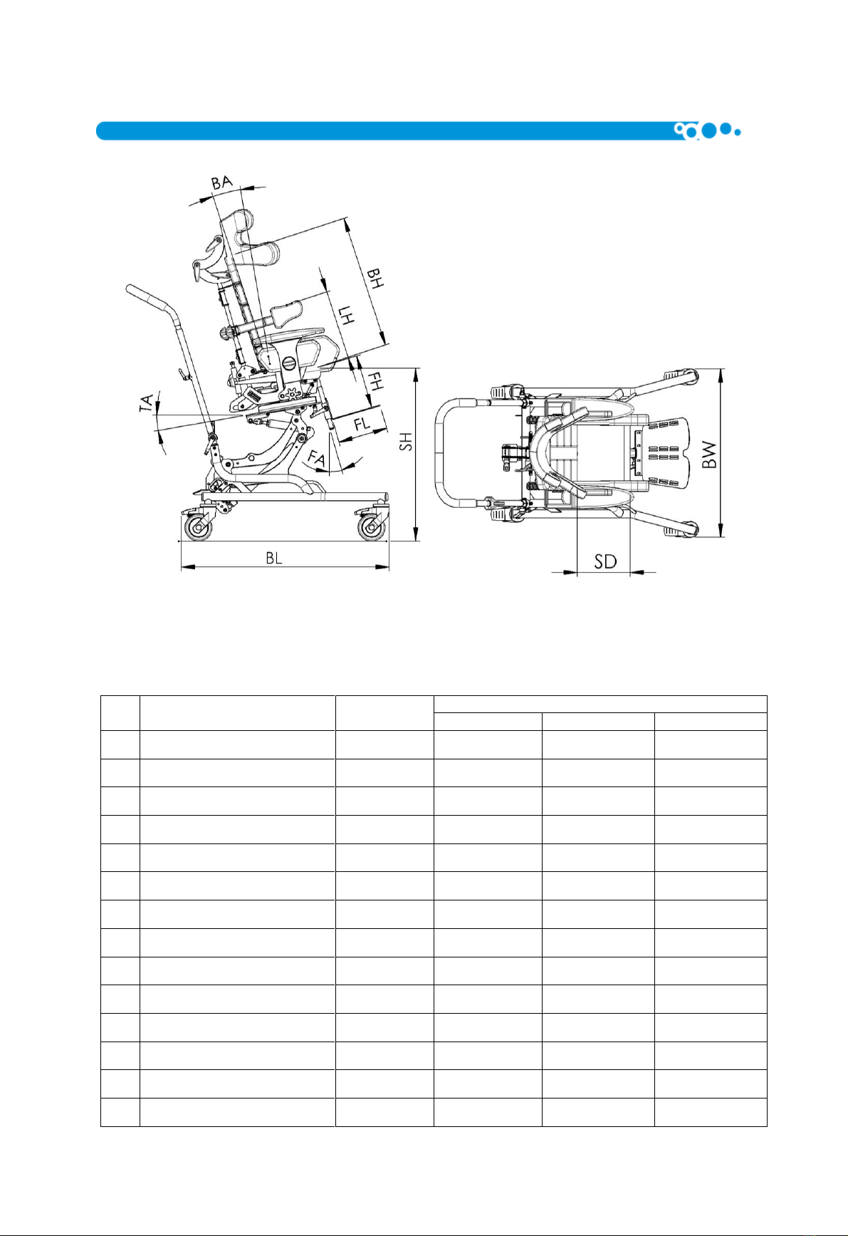
5. Technical Specification............................................................................................................................................................................ 5
6. Adjustments and fitting........................................................................................................................................................................... 6
1. Adjustment ............................................................................................................................................................................................. 6
6.1 Width Adjustment ............................................................................................................................................................................. 6
6.2 Depth Adjustment ............................................................................................................................................................................. 6
6.3 Backrest Adjustment.......................................................................................................................................................................... 7
6.4 Backrest Angle Adjustment................................................................................................................................................................ 8
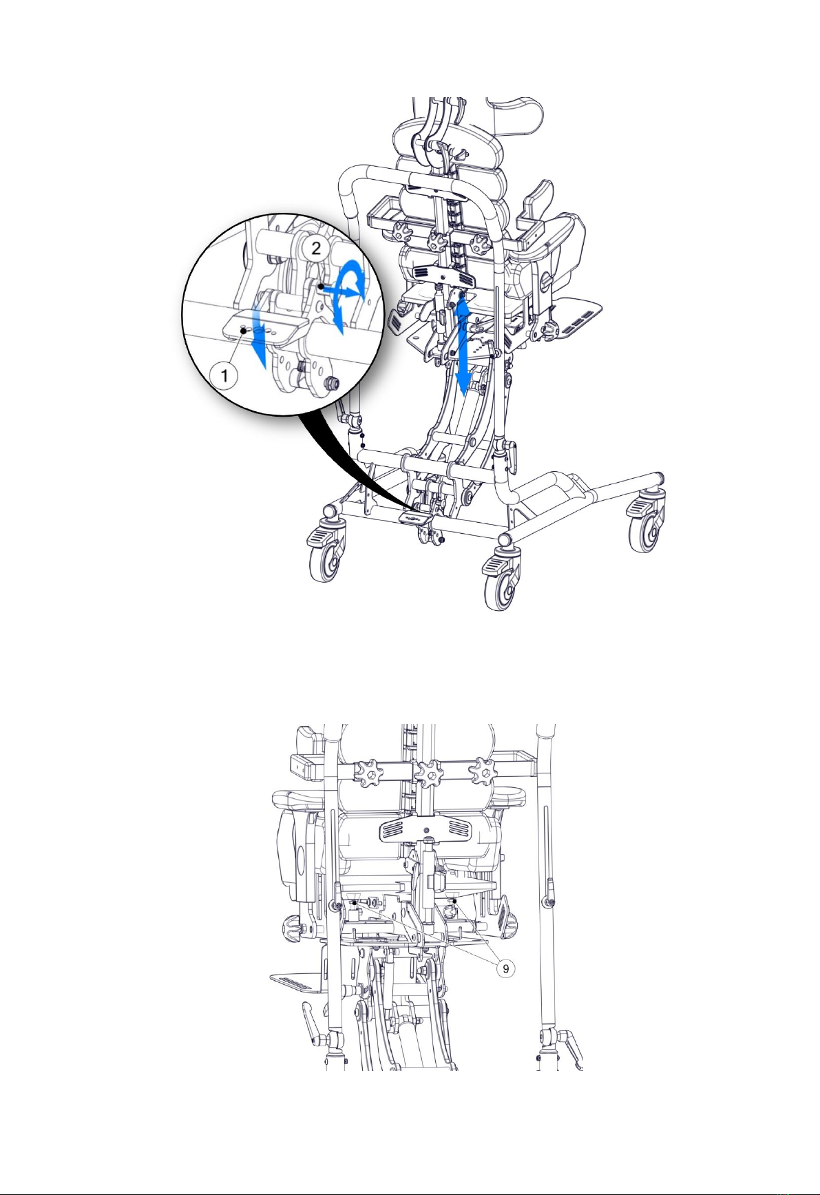
6.5 Raising and lowering the seating system ........................................................................................................................................... 8
6.6 Buttock Support Height Adjustment.................................................................................................................................................. 9
6.7 Footrest Length Adjustment ............................................................................................................................................................ 10
6.8 Footrest Angle Adjustment.............................................................................................................................................................. 10
6.9 Armrest Height Adjustment............................................................................................................................................................. 11
6.10 Adjusting the seat angle .................................................................................................................................................................. 12
6.10.1 Regulating the seat’s tilt angle using the lever ................................................................................................................ 12
6.10.2 Adjusting the angle by using the gas spring..................................................................................................................... 13
6.11 Wheel brakes................................................................................................................................................................................... 13
6.12 Adjusting the push handle ............................................................................................................................................................... 14
6.12.1 Regulating the push handle –folding in one position...................................................................................................... 14
6.12.2 Regulating the push handle –folding in two position...................................................................................................... 14
7. Accessories............................................................................................................................................................................................ 15
7.1 Headrest .......................................................................................................................................................................................... 15
7.1.1 Headrest Assembly.......................................................................................................................................................... 16
7.1.2 Headrest Adjustment ...................................................................................................................................................... 16
7.2 Side Supports................................................................................................................................................................................... 16
7.2.1 Assembly of side supports ............................................................................................................................................... 16
7.2.2 Width adjustment of side supports ................................................................................................................................. 16
7.2.3 Height adjustments of side supports ............................................................................................................................... 16
7.3 Space adjustment of thigh supports ................................................................................................................................................ 16
7.4 Fixing and Adjusting the Vest, Legs abduction belts and Pelvic Belts .............................................................................................. 17
7.5 Push handles for the seating system ............................................................................................................................................... 18
7.6 Table................................................................................................................................................................................................ 18
7.6.1 Adjusting the Spacing of the Table Handles .................................................................................................................... 18
7.6.2 Table Assembly................................................................................................................................................................ 19
7.6.3 Table Tilt Angle Adjustment ............................................................................................................................................ 20
7.7 Separate Footplates......................................................................................................................................................................... 20
7.8 Spine interlock adjustment.............................................................................................................................................................. 21
7.9 Seat interchangeable system –polyamide trapezoid ...................................................................................................................... 22
8. Moving device....................................................................................................................................................................................... 23
9. General Care & Cleaning ....................................................................................................................................................................... 24
10. Service & Maintenance.................................................................................................................................................................... 25
11. Identification plate .......................................................................................................................................................................... 25

Baffin neoSIT HL Edition 1 3
1. Introduction
Thank you for purchasing BAFFIN neoSIT HL - orthopaedic seat for children, stabilising the back and head, by LIW Care
Technology Care Sp. z o.o. We are certain that the innovative device with advanced anatomical body adjustment features
will improve the comfort of work and leisure time for the user in the sitting position.
Developed by LIW Care Technology Sp. z o.o., the BAFFIN neoSIT HL - orthopaedic seat for children stabilising the back
and head has been designed to provide an alternative to standard orthopaedic seats with limited anatomical adjustment
ranges and bespoke seats which perfectly map out the body curvatures, however, they do not give the opportunity to
correct the user’s body posture.
We ensured that the seat is as simple to use as possible while giving the opportunity to fit the anatomical shape of the
user, as well as correct the posture.
For safety and comfort whilst using the BAFFIN neoSIT HL and to avoid the risk of any damage to the equipment, it is
very important to read these instructions before use and to ensure the recommendations and warnings, are read and
understood, by the user and/or any others involved in operating the equipment.
Warnings & Safety Information
For LIW Care Technology Sp. z o. o., the most important thing is to protect the patients who use our equipment. To
ensure the safety of BAFFIN neoSIT HL users, the following recommendations should be adopted:
1. Please read the instructions before first use. If any questions or doubts should arise, please contact your
dealer or the manufacturer.
2. Please make sure that all information, tips and warnings included in these chapters are well understood.
In these instructions for LIW Care Technology Sp. z o. o. products, you will find information marked with the ‘’NOTE!”
symbol. It is used to the draw the reader’s particular attention to the text. It looks as follows:
NOTE! THE SYMBOL IS USED TO DRAW THE READER’S ATTENTION TO THE TEXT
WHICH IS MARKED WITH THIS SYMBOL. FAILURE TO COMPLY WITH THE
INSTRUCTIONS MAY ENDANGER THE HEALTH AND SAFETY OF THE USER OR
CAUSE DAMAGE THE PRODUCT.
NOTE! THE USER SHOULD NOT BE TRANSPORTED IN THE BAFFIN NEOSIT RS IN A
VEHICLE.
NOTE! IT IS IMPORTANT THE REGULAR SERVICE AND MAINTENANCE IS CARRIED
OUT. THIS WILL MAXIMISE THE LIFE OF THE EQUIPMENT.
2. Symbol meaning
Manufacturer’s name and date of manufacture
Serial Number
Maximum user weight

Baffin neoSIT HL Edition 1 4
Avoid contact with water
Note! Follow product instructions
Unlocking direction
Movement direction
Mark of conformity in accordance with EU Directive 93/42 EEC Annex. VII, concerning
medical devices
3. Intended Use of the Device
BAFFIN neoSIT HL - orthopaedic seat for children, stabilising the back and head meets the essential requirements of
the MDD 93/42 EEC for medical devices.
BAFFIN neoSIT HL - orthopaedic seat for children, stabilising the back and head, in accordance with Annex IX of the
MDD 93/42 EEC, is non-invasive non-active I class medical device according to rule 1.
Declaration of Conformity for this product is available from the manufacturer's Sales Department.
NOTE! IF PRODUCT HAS BEEN MODIFIED USING NON - AUTHENTIC PARTS OR PARTS
PRODUCED BY ANOTHER MANUFACTURER, REMOVE THE CE MARK.
4. Indications for product use
The BAFFIN neoSIT HL is intended for users whose height is within the 85 -130 cm range, with a weight limit of 60 kg.
Intended Users are those with faulty postures and muscle dysfunction. Particular conditions include cerebral palsy,
muscular dystrophy, paralysis of various types, tetra and paraplegia. It can be used in treatment to help prevent the
consequences of postural defects and malfunctioning of the body connected with them. The device makes it possible to put
the spine and pelvis in a correct (optimal) position. An innovative feature of this device is that it “grows” with the child as it
can be adjusted to their current position and height. If you have any questions or doubts, contact your equipment
provider/clinician in the first instance.

Baffin neoSIT HL Edition 1 5
5. Technical Specification
Fig. 1
There are three sizes of the Baffin neoSit HL. Size details are shown in the table below:
No.
Dimension
Dimension
symbol
Dimension [cm]
S
M
L
1
Seat height
SH
37÷68
37÷68
37÷68
2
Back height
BH
42
50
58
3
Back angle
BA
-5°÷25°
-5°÷25°
-5°÷25°
4
Base length
BL
77
77
77
5
Base width
BW
63
63
63
6
Foot platform height
FH
17÷27
17÷27
28÷38
7
Foot platform length
FL
18
18
21
8
Wheel diameter
RW
10
10
10
9
Seat depth
SD
16÷31
20÷31
27÷40
10
Seat width
SW
15÷30
15÷30
20÷32
11
Footplate angle
FA
-10°÷45°
-10°÷45°
-10°÷45°
12
Tilt angle
TA
-10⁰÷30⁰
-10⁰÷30⁰
-10⁰÷30⁰
13
Lateral support height
LH
16÷35
16÷40
20÷45
14
Maximum user's weight
60kg
60kg
60kg

Baffin neoSIT HL Edition 1 6
6. Adjustments and fitting
NOTE! PRIOR TO USING THE DEVICE, MAKE THE FOLLOWING ADJUSTMENTS TO FIT
IT TO THE USER’S BODY.
NOTE! AFTER EVERY SINGLE ADJUSTMENT, YOU NEED TO MAKE SURE THAT ALL THE
COMPONENTS ARE CORRECTLY POSITIONED AND LOCKED.
1. Adjustment
6.1 Width Adjustment
To adjust the side pelvic supports turn knob 1 right or left until the required dimensions are obtained.
The adjustment elements are situated on the left and right, allowing for symmetrical and asymmetrical positioning of the
user's pelvis.
Fig. 2
6.2 Depth Adjustment
To unlock, loosen bolts 3 located on each side. After unlocking the screws, set the depth by pushing or pulling the front part
of the device. To lock, tighten bolts 3. If the adjustment range provided by the bolts 3 is not sufficient, additional
adjustment may be obtained by loosening bolts 7 and pulling or pushing the backrest. After completing the adjustment
procedure, make sure the bolts 7 are tightened.

Baffin neoSIT HL Edition 1 7
Fig. 3
6.3 Backrest Adjustment
The backrest has a unique design enabling the user to obtain its corrective or anatomical shape. The central core comprises
several independent segments. The backrest can be modelled anatomically after loosening the adjustment screw 10. After
the backrest optimum shape is obtained, re-tighten the adjustment screw 10.
Fig. 4

Baffin neoSIT HL Edition 1 8
NOTE! THE ADJUSTMENTS MUST BE CARRIED OUT PRECISELY AS THEY HAVE IMPACT
ON THE SPINE POSITION.
6.4 Backrest Angle Adjustment
To change the angle of the backrest, the lever 4 should be turned and hold, the required angle position should be adjusted
with the help of a hand, and then the lever should be released.
Fig. 5
NOTE! WHILE THE PATIENT IS GIVING PRESSURE TO THE BACK, RELEASING OF THE
LEVER WILL CAUSE THE RAPID FALL OF ONE, SO THE FALLING BACK SHOULD BE ALWAYS
PROTECTED BY THE HAND!
6.5 Raising and lowering the seating system
NOTE! WHILST LOWERING THE SEAT PLATFORM WITH THE USER, PRESS THE
RETARDANT PEDAL AND HOLD THE HANDLE UNDER IN THE SEAT BASE WITH BOTH
HANDS. UNSER NO CIRCUMSTANCES HOLD/ PUT HANDS NEAR THE MOTION
MECHANISM OF THE SEAT BASE; THERE IS A RISK OF HAND ENTRAPMENT!
One of the features of Baffin neoSIT HL, orthopaedic seat stabilising the head and back for children, is the option to adjust
its height. The motion mechanism is designed in such a way that while changing the seat height, the tilt angle does not
change in relation to the basis. The seat movement is supported by a gas spring. The spring has been selected in such a
way that it prevents the seat from raising independently with its user; it is only possible with the aid of a carer. The upward
and downward movement of a slow character and is suppressed by the force of the gas spring.
In order to change the seat height, press the retardant pedal (1) and set the required height. The retardant mechanism has
an immobiliser to prevent accidental operation in the form of a bolt (2).
To unlock the adjustment feature, pull away the bolt lever (2) and turn it by approximately 90°; this will permanently unlock
the lifting mechanism. After setting up the platform height, you must secure the mechanism against an accidental use by
turning the bolt lever again (2) so that the locking mechanism is inserted again.

Baffin neoSIT HL Edition 1 9
Fig. 6
6.6 Buttock Support Height Adjustment
Turn screw 9 until the required height is obtained.
Fig. 7

Baffin neoSIT HL Edition 1 10
NOTE! SCREWS 9 ARE LOCATED ON THE LEFT AND RIGHT SIDE OF THE DEVICE AND ARE
INDEPENDENT FROM EACH OTHER, TO ENSURE ASYMMETRICAL ADJUSTMENT OF THE
BUTTOCK SUPPORTS.
NOTE! TAKE PARTICULAR CARE WHEN ADJUSTING THE GLUTEAL SUPPORT, AS IT
AFFECTS POSITIONING OF THE SPINE.
In order to facilitate the adjustment, it is possible to remove the upholstery from the seat in order to provide access to the
buttock ports.
6.7 Footrest Length Adjustment
To unlock, loosen knob 5. Move the footrest to the required length. Re-tighten knob 5 to lock into position.
Fig. 8
6.8 Footrest Angle Adjustment
Loosen handle knob 8, set the required angle and re-tighten knob 8.

Baffin neoSIT HL Edition 1 11
Fig. 9
6.9 Armrest Height Adjustment
Turn knob 12 until the required height is set. The knobs are located on the left and right side. They operate independently
from each other, making it possible to adjust the armrest height asymmetrically.
Fig. 10

Baffin neoSIT HL Edition 1 12
NOTE! ONLY AUTHORISED PEOPLE CAN SET AND ADJUST THIS PRODUCT. THE SETTING
AND ADJUSTMENT MUST BE CARRIED OUT BY A QUALIFIED CLINICIAN OR AUTHORISED
QUALIFIED PERSONNEL.
CHECK PRECISELY THAT THE ADJUSTMENT IS CORRECT:
1. NO ELEMENT EXERTS EXCESSIVE PRESSURE ON USER'S BODY.
2. THERE IS NOT TOO MUCH FREE SPACE BETWEEN THE USER AND THE
DEVICE.
3. ALL ADJUSTMENT SCREWS AND KNOBS ARE RE-TIGHTENED AFTER THE
ADJUSTMENT PROCESS IS COMPLETED.
6.10 Adjusting the seat angle
BAFFIN neoSIT HL seat has the option to have the tilt adjusted in relation to the basis. Depending on the version of the
device, it is operated either manually by using a lever or supported by a gas spring.
NOTE! AT THE MAXIMUM BACKWARDS TILT OF THE SEAT (30 DEGREES), THE
POSSIBILITY OF LOWERING THE SEAT COMPLETELY BECOMES RESTRICTED; IT
RESULTS FROM THE KINEMATIC SYSTEM OF THE DEVICE AND DOES NOT
RESTRICT ANY REHABILITATION FUNCTIONS.
6.10.1 Regulating the seat’s tilt angle using the lever
NOTE! DURING ADJUSTING THE TILT ANGLE OF THE SEAT WITH ITS USER, HOLD
THE RETARDANT’S LEVER WITH ONE HAND AND THE HANDLE WITH THE OTHER
ONE. UNDER NO CIRCUMSTANCES HOLD/ PUT HANDS NEAR THE SEAT
MECHANISM; THERE IS A RISK OF HAND ENTRAPMENT!
To set the required tilt angle of the seat, hold the seat by the handle, loosen the tilt lock by gently opening the release
lever (2), arrange the seat in the required position and retighten the release lever. (2). Remember that the forward tilt is
done by the force of the person operating the device. This may be more difficult for a patient with a maximum weight
permitted. In this case, where possible, it is advisable to perform adjustments with the patient out of the seat.
Rys. 11

Baffin neoSIT HL Edition 1 13
6.10.2 Adjusting the angle by using the gas spring
NOTE! DURING ADJUSTING THE TILT ANGLE OF THE SEAT WITH USER IN IT,
HOLD THE RETARDANT’S LEVER WITH ONE HAND AND THE HANDLE WITH THE
OTHER ONE. UNDER NO CIRCUMSTANCES HOLD/ PUT HANDS NEAR THE
PLATFORM MECHANISM; THERE IS A RISK OF HAND ENTRAPMENT!
To set the seat at the required tilt angle, hold the seat by the handle, release the gas spring lever (3); the gas spring
supports the platform’s movement. Once the required position has been achieved, release the gas spring lever – this will
lock it. Remember that the forward tilt is done by the force of the person operating the device. This may be more difficult
for a patient with a maximum weight permitted. In this case, where possible, it is advisable to perform adjustments with
the patient out of the seat.
Fig. 12
6.11 Wheel brakes
Baffin neoSIT’s HL Frame is equipped with four independent wheel brakes (1); brake levers are located directly on the
wheels. To apply the brake, press the brake lever down (2). To release the brake, lift the brake up. The wheel brakes are
operated by foot.
Fig. 13

Baffin neoSIT HL Edition 1 14
NOTE! STABILITY OF THE DEVICE MAY BE AT RISK IN THE EVENT OF
UNEXPECTED PUSH, TILTING OR LEANING ON IT.
6.12 Adjusting the push handle
Baffin neoSIT HL is equipped with a push handle used for transporting the device. Depending on the version, the seating
system can be equipped with a push handle -folding in one or two positions.
6.12.1 Regulating the push handle –folding in one position.
To tilt the angle of the adjustable push handle (3), gently undo both levers (1) located at either side of the handle, set the
required angle and retighten both levers. To set the height of the handle (3), gently loosen both levers (2), then set the
required handle height and retighten them.
Fig. 14
6.12.2 Regulating the push handle –folding in two position.
To tilt the angle of the adjustable push handle (4), gently undo both levers (1) located at either side of the handle, set the
required angle and retighten both levers. To set the appropriate position of the top part of the handle (5), gently undo both
levers (3) at each side of the handle, set the appropriate position of the top of the handle and retighten both levers. To set
the height of the handle (4), gently loosen up both levers (2), set the required height of the handle and retighten both
levers.

Baffin neoSIT HL Edition 1 15
Fig. 15
7. Accessories
7.1 Headrest
Fig. 16

Baffin neoSIT HL Edition 1 16
7.1.1 Headrest Assembly
- Loosen the top adjustment screw spine 17.
- Insert the headrest fixing bracket 15 onto the backrest profile 16.
- Tighten the top adjustment screw 17.
7.1.2 Headrest Adjustment
- Loosen the adjustment knobs 18.
- Set the headrest in the correct position.
- Tighten the adjustment knobs 18.
7.2 Side Supports
Fig. 17
7.2.1 Assembly of side supports
-Insert the arm support fixing bracket 20 onto the backrest profile 16.
-Slide the support plates 21 through the opening 22 located in the support fixing bracket.
- Tighten the fixing screw 23.
7.2.2 Width adjustment of side supports
- Loosen the screws 24 and 25.
- Draw the arm supports aside or towards each other until the required width is obtained.
- Tighten the screws 24 and 25.
7.2.3 Height adjustments of side supports
- Loosen the screw 23.
- Move the arm support 20 up or down until the required height is obtained.
- Tighten the screw 23.
7.3 Space adjustment of thigh supports
Space regulation of thigh supports is done by using two regulatory screws (1), found underneath the thigh supports.
To regulate, lift the upholstery covering the thigh brackets and loosen the regulatory screw (1) to allow for free movement
and setting the thigh supports into position. After setting the desired position, tighten the regulatory screw to lock the thigh
supports in a particular position. Thigh Supports can be set at an angle relative to the devices length hence allowing for ten
ways of setting the thighs. Adjusting the thigh supports affects the proper positioning of the knee and pelvis. Independent
regulation of the thigh supports, allows for asymmetric adjustments.

Baffin neoSIT HL Edition 1 17
Fig. 18
7.4 Fixing and Adjusting the Vest, Legs abduction belts and Pelvic Belts
The vest and the pelvic belts are fixed to the device with the use of belts. To fix the vest correctly, pass the fastening belts
through the holes in fastening loops 26. The length of the fastening belts can be adjusted by passing the belts through
fastening loops on the backrest, or through the buckles which fix the belts to the vest. The pelvic belts are fixed to the
fastening loops located behind the armrests 27. The length of the belts is adjusted by passing the fastening belts (loosening
or tightening) through the fastening buckles or loops.
Fig. 19

Baffin neoSIT HL Edition 1 18
NOTE! CHECK PRECISELY THAT THE ADJUSTMENT IS CORRECT:
1. NO ELEMENT EXERTS EXCESSIVE PRESSURE ON USER'S BODY.
2. THERE IS NOT TOO MUCH FREE SPACE BETWEEN THE USER AND THE
DEVICE.
3. ALL ADJUSTMENT SCREWS AND KNOBS ARE RE-TIGHTENED AFTER THE
ADJUSTMENT PROCESS IS COMPLETED.
4. MAKE SURE ALL BELTS ARE CORRECTLY FIXED IN THE FASTENING LOOPS
AND ALL VEST AND HIP BELT BUCKLES ARE CORRECTLY SECURED.
7.5 Push handles for the seating system
The push handles of the seating system (1) are used when the handle bar is dismounted (3). They are mounted directly on
the platform, used for raising the seating system (2), by joining elements.
Fig. 20
7.6 Table
7.6.1 Adjusting the Spacing of the Table Handles
Fig. 21

Baffin neoSIT HL Edition 1 19
To adjust the spacing of the table handles 1 to the spacing of the table sockets 2 located in the armrests, loosen the screws
5, which can be found on the table handles under the table top. Join or draw the handles apart adjusting them to the
spacing of the sockets and tighten the table handles screws.
7.6.2 Table Assembly
Fig. 22
To fit the table, loosen the locking knobs 3 and slide the table handles 1 into the sockets located under the armrests 2. After
inserting the table to the proper depth, re-tighten the locking knobs 3.
Table of contents
Other LIW Medical Equipment manuals
Popular Medical Equipment manuals by other brands

Saadat
Saadat Dena 1210 user manual

Bionet
Bionet Cardio7-S Operation manual

Accurate Bio-Medical Technology
Accurate Bio-Medical Technology WS Series user manual

Zeiss
Zeiss ATLAS 9000 quick start guide

Bio Compression Systems
Bio Compression Systems SC-3004-DL-230 operating instructions

EDAN
EDAN SE-1200 Series user manual

Cardiac Science
Cardiac Science Powerheart AED G3 Plus 9390E Operator's and service manual

BD
BD PureWick PW200E User's guide and warranty

Codonics
Codonics SLS550i manual

Veridian Healthcare
Veridian Healthcare ProKit 02-127 Series instruction manual

Arjo
Arjo Maxi Sky 2 PLUS Quick reference guide

Medela
Medela Thopaz Instructions for use