LIW BAFFIN Automatic User manual

MANUAL FOR
BAFFIN Automatic
Sizes: S,M,L
Control: Automatic
Edition 1 –18.07.2017

2
NOTE! THE MANUFACTURER IS SOLELY RESPONSIBLE FOR THE EQUIPMENT
PURCHASED FROM A DIRECT REPRESENTATIVE OF LIW CARE TECHNOLOGY, OR IN
SPECIALIZED MEDICAL SHOP REPRESENTING LIW CARE TECHNOLOGY IN POLAND.
NOTE! DEVICE IS DEDICATED FOR INDOOR USE, NO TRESHOLDS ACCEPTABLE.
NOTE! WHILE USING AND SERVICE, ALSO DURING INSTALLATION AND
ADJUSTMENT ALL THE MECHANISMS, THERE IS A DANGER OF ENTRAPMENT OR/
AND COMPRESSION SOME PARTS OF A USER/ USER’S ASSISTANT BODY INSIDE OF
THE GAPS/ SLOTS BETWEEN ELEMENTS. THIS ACTION SHOULD BE TAKEN WITH
EXTRA PRECAUTION. AFTER FINISHING ADJUSTMENT, THERE IS A NEED TO
STABILIZE POSITION BY PRECISE TIGHTENING OF THE KNOBS/ BOLTS.
NOTE! READ THE MANUAL NECESSAIRLY BEFORE START-UP.

3
Table of Contents
1. General information .................................................................................................................................................................................. 4
1.1 Introduction.......................................................................................................................................................................................... 4
1.2 General safety conditions.....................................................................................................................................................................4
2. Construction of the Multifunctional device ...............................................................................................................................................4
2.1 Technical parameters of BAFFIN Automatic Multifunctional device ....................................................................................................6
3. Intended Use..............................................................................................................................................................................................7
4. Adjustment and adaptation .......................................................................................................................................................................7
4.1 Adjusting the width and depth of the Multifunctional device..............................................................................................................7
4.1.1 Adjusting the width......................................................................................................................................................................... 7
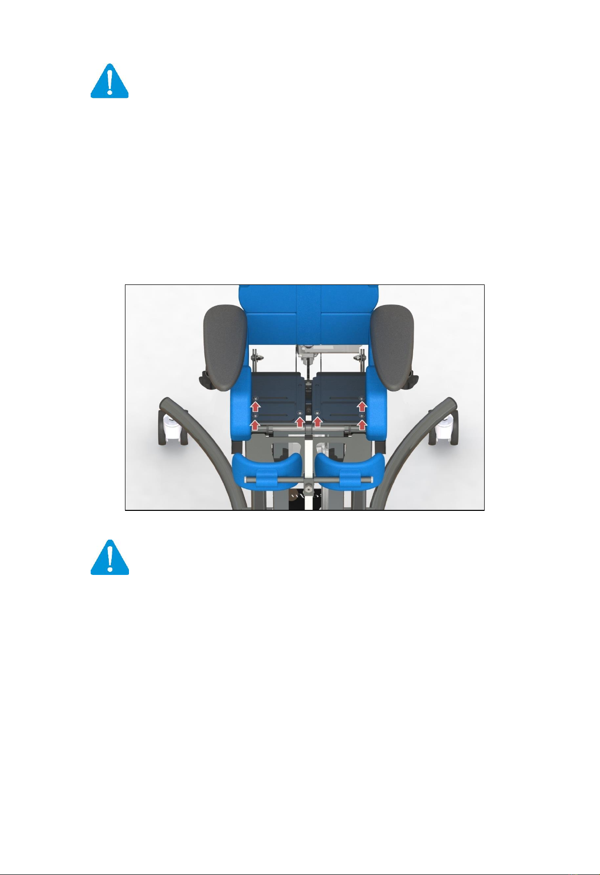
4.1.2 Adjusting the spacing of thigh supports..........................................................................................................................................8
4.1.3 Adjusting the depth.........................................................................................................................................................................8
4.1.4 Adjusting the seat position..............................................................................................................................................................9
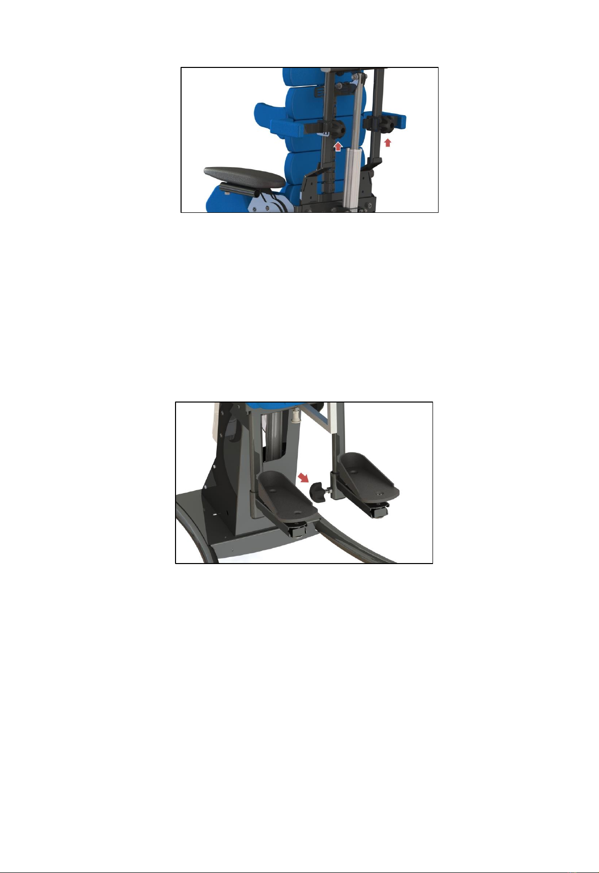
4.2 Adjusting the width and height of arm/side supports ..........................................................................................................................9
4.3 Adjusting the footrest......................................................................................................................................................................... 10
4.3.1 Adjusting the height of the footrest..............................................................................................................................................10
4.3.2 Adjusting the angle and position of the foot platform ..................................................................................................................10
4.4 Kneepad fitting and adjustment .........................................................................................................................................................11
4.4.1 Adjusting the kneepads.................................................................................................................................................................11
4.5 Modelling (fitting) the backrest ..........................................................................................................................................................12
4.6 Fixing and adjusting the vest and lap belts .........................................................................................................................................13
5. Repositioning manual ..............................................................................................................................................................................13
5.1 Changing the position from sitting to recumbent...............................................................................................................................14
5.2 Changing the position from sitting to upright.....................................................................................................................................14
6. Additional equipment ..............................................................................................................................................................................15
6.1 Headrest............................................................................................................................................................................................. 15
6.1.1 Adjusting the headrest..................................................................................................................................................................15
6.1.2 Headrest adjustment .................................................................................................................................................................... 15
6.2 Table...................................................................................................................................................................................................16
6.2.1 Adjusting the spacing of table handles..........................................................................................................................................16
6.2.2 Installing the table ........................................................................................................................................................................16
6.2.3 Adjusting the angle of the table ....................................................................................................................................................17
6.3 Battery................................................................................................................................................................................................17
6.4 Push handle ........................................................................................................................................................................................18
7. Handling the device .................................................................................................................................................................................19
8. General Care and Cleaning.......................................................................................................................................................................20
8.1 Cleaning and maintenance recommendations ...................................................................................................................................20
8.2 Disinfection.........................................................................................................................................................................................20
9. Disposal of the product............................................................................................................................................................................21
10. Service and Maintenance ...................................................................................................................................................................21
11. Identification plate ...........................................................................................................................................................................21
12. Symbols meaning ...............................................................................................................................................................................22
13. Compliance with the safety requirements for medical devices..........................................................................................................22
WARRANTY CARD ...............................................................................................................................................................................................23

4
1. General information
1.1 Introduction
The BAFFIN Automatic Multifunctional device developed by LIW Care Technology sp. z o.o. was designed and patented to provide new
quality in rehabilitation. We have made every effort to ensure that BAFFIN Automatic Multifunctional device was as easy to use as possible
while providing vast anatomical adjustment possibility and the best posture correction. Before using the Multifunctional device, please
familiarise yourself with this manual. By following all recommendations included in this manual, you will be able to avoid any situations
that might damage the equipment and ensure your safety and comfort while using the device. You will be able to take full advantage of all
the benefits of the device only when it is properly fitted to the patient's body and their personal needs.
1.2 General safety conditions
The biggest concern of LIW Care Technology Sp. z o.o. is to ensure the safety of our patients using the device. In order to guarantee full
safety of the user of our stander, you have to follow these recommendations:
1. Prior to any attempt to use the device, thoroughly familiarise yourself with this manual. If in doubt, contact the seller or
manufacturer.
2. Make sure that all the information, recommendations and warnings contained in these chapters are fully
comprehensible. This manual includes paragraphs marked WARNING, which is meant to call special attention to its
contents. It means the following:
NOTE!
This symbol is used to call the reader's attention to the text below.
FAILURE TO FOLLOW THE CONTENTS OF THIS PARAGRAPH MAY BE HAZARDOUS TO THE USER'S
HEALTH AND LIFE, AS WELL AS TO THE SAFETY OF THE DEVICE.
2. Construction of the Multifunctional device
The Baffin Automatic Multifunctional device consist of
1
1 –Central Core (Spine)
2 –Back Support
3 –Side Support
4 –Hip Support
5 - Armrest
6 –Knee Support
7 –Footrest
8 –Foot Platform
9 –Standing Base
10 –Seat
11 - Actuators
12 –Headrest
1
The equipment of Baffin Automatic Multifunctional device is available depending on the Continent, Country.

5
Fig. 1 Frame Work Of The Multifunctional device

6
2.1 Technical parameters of BAFFIN Automatic Multifunctional device
Three sizes of the Multifunctional device are available.
Basic dimensions are given in the table below:
S (cm)
M (cm)
L (cm)
1
Seat height (SH)
69
69
69
2
Back height (BH)
44
52
60
3
Back angle (BA)
00÷900
00÷900
00÷900
4
Verticalization range (VR)
00÷860
00÷860
00÷860
5
Base length (BL)
88
88
88
6
Base width (BW)
65
65
65
7
Foot platform height (FH)
16÷33
16÷33
30÷48
8
Foot platform length(FL)
17
21
23
9
Wheel diameter (RW)
7,5
7,5
7,5
10
Seat depth (SD)
18÷28
21÷31
29÷39
11
Seat width (SW)
18÷29
22÷33
22÷33
12
Footrest angle (FA)
00÷900
00÷900
00÷900
13
Footplate angle (FA1)
-/+50
-/+50
-/+50
14
Footplate angle (FA2)
-/+450
-/+450
-/+450
15
Footplate depth range (FD)
6
6
6
16
Footplate width range (FW)
10÷30
12÷35
12÷35
17
Tilt angle (TA)
130
130
130
18
Lateral support height (LH)
21÷38
21÷38
21÷40
19
Maximum user’s weight
40kg
60kg
60kg
20
Weight of the device
34,1kg
38kg
39,5kg

7
3. Intended Use
BAFFIN Automatic Multifunctional device can be used in patients with posture and muscle dysfunction. It is perfect for
children with cerebral palsy, muscular dystrophy, palsies of various origins, tetra-and paraplegias as well as for children with
abnormal posture of the body. It can be used therapeutically and prophylactically to prevent the inevitable consequences of
childhood illnesses (postural deformities and related malfunctions of the body). The device allows for putting a child's spine
and pelvis in optimal position. Proper posture improves the quality of life. The three basic systems: respiratory, circulatory
and digestive function better. The use of a Multifunctional device following exercise will increase the chances of full postural
recovery. Owing to a design that, when properly adjusted, attempts to restore the physiological curvature of the spine, it
perfectly and smoothly corrects scoliosis, as well as passively restores proper alignment of the spine's kyphosis and lordosis.
Pelvis adjustment (pelvis is the base of the body in a sitting position) corrects spine position, which forces the whole body of
the patient to be more correct. Smooth adjustment of buttock load is perfect in preventing and curing sores, and decreases
skin abrasion. The device allows for maintaining the child's head in a proper position, which facilitates feeding, education and
playing. Each device is individually fitted for a given child. Our innovative device “grows” with a child. It can be adapted to the
current position and height of the child.
Apart from upright position, the BAFFIN Automatic Multifunctional device allows the child to sit and lie down.
4. Adjustment and adaptation
NOTE:
Adjustment and adaptation have to be performed by a person authorised by the manufacturer of the
Multifunctional device. The adjustments listed below have to be made according to doctor's or physical
therapist's recommendations.
4.1 Adjusting the width and depth of the Multifunctional device
4.1.1 Adjusting the width
The width of the seat can be adjusted using the knob (3) marked with a red arrow (fig. 2). The knobs are located on the right
and left sides of the device. Their effect is independent of each other. This enables symmetrical and asymmetrical positioning
of the user's body.
To change the width of the left or right side:
a) loosen the securing bolts (1 and 2) on the back and bottom of the device using the allen key 4mm (fig. 2).
b) turn the knob (3) marked with a red arrow using the allen key 4mm (fig. 2) to change the width of the left or right side of
the device.
c) tighten the securing bolts (1 and 2) on the back and bottom of the device (fig. 2).
Repeat this procedure for the opposite side if necessary.
Fig. 2 Adjusting the width

8
4.1.2 Adjusting the spacing of thigh supports
Thigh support spacing adjustment is done using two adjustment screws below the supports (fig. 3). In order to make the
adjustment, raise the upholstery on the thigh supports and loosed the adjustment screws to position the supports
appropriately. After setting the desired position, tighten the adjusting screw to lock the supports in place. Thigh supports can
be positioned at an angle to the longitudinal axis of the device, thus increasing thigh angle. Thigh support positioning has an
impact on the correct position of knees in relation to the pelvis.
Fig. 3 Adjusting the spacing of thigh supports
The adjustment screws are located on the right and left sides of the device. Their effect is independent of each other. This
enables symmetrical and asymmetrical positioning of the user's body.
NOTE:
After adjustments are made, make sure that all the adjusting screws are tightened. Failure to tighten
them may be hazardous to the patient and may damage the device.
4.1.3 Adjusting the depth
Seat depth can be adjusted by sliding the back of the device into or out of the base. Adjustments should be carried out with
the device in the full sitting position.
In order to make the adjustment, loosen the knobs on the side pulls (fig. 4) on the right and left sides of the device, then
loosen the securing screws located underneath the seat (fig. 4) on the right and left sides. Next, insert or pull out the rear of
the unit (backrest and actuator) to obtain the desired depth of the seat. After adjustment, tighten the previously loosened
screws, pulls and securing screws.
Fig. 4 Adjusting the depth

9
NOTE:
Adjustments should be carried out with the device in the full sitting position. After adjustments are
made, make sure that all the adjusting screws are tightened. Failure to tighten them may be hazardous
to the patient and may damage the device. Once the depth adjustment is done, adjust the seat position
(see section 4.1.4)
4.1.4 Adjusting the seat position
Seat position is adjusted by sliding the right and left seat supports back or forward (fig. 5). The adjustment should be carried
out with the device in a recumbent position, after loosening all six screws (three per each support). A properly adjusted seat
will have a space of approx. 1 cm between the seat supports (left and right) and the bottom of the backrest when the device
is in a recumbent position.
In order to make the adjustment, remove the cushions from the seat and loosen all six screws securing the left and right seat
supports (three per each support) (fig. 5). Put the device in a recumbent position and slide the seat supports back or forward,
so there is a space of approx. 1 cm between the supports and the bottom of the backrest. After the adjustment is completed,
tighten all six screws.
Fig. 5 Adjusting the seat position
NOTE:
The adjustment should be done with the device in a recumbent position after loosening all securing
screws. After each depth adjustment, make sure none of the seat supports collide with the backrest.
4.2 Adjusting the width and height of arm/side supports
The width and height of arm supports are adjusted using the knobs marked with a red arrow (fig. 6). Left and right armpit
supports are adjusted independently. The knobs are located on both sides of the unit and operate independently of each
other, making it possible to set the supports symmetrically and asymmetrically with respect to the axis of the body.
To adjust the height and width of the arm support, loosen the adjustment knob (fig. 6), set the armpit support in the desired
position and tighten the adjustment knob. Perform an analogous regulation on the opposite side.

10
Fig. 6 Adjusting the width and height of arm/side supports
4.3 Adjusting the footrest
The footrest is used to support the feet while sitting, lying down and tilting. The following parameters of the footrest can be
adjusted:
- height,
- angle and position of the foot platform
4.3.1 Adjusting the height of the footrest
The footrest height adjustment knob is marked with a red arrow (fig. 7). In order to change the height, loosen the knob and
move the footrest up or down. After setting the desired height, tighten the knob as much as possible. Footrests can be
adjusted independently of each other, so that they can match lower limbs of different length.
Fig.7 Adjusting the height of the footrest
4.3.2 Adjusting the angle and position of the foot platform
In order to adjust the angle and position, use three adjustment screws located underneath the platform support. Adjustment
is made by changing the angle and/or position of the foot platform.
In order to adjust it, loosen the three adjustment screws (fig. 8) underneath the foot platform support, set the platform to
the desired position and tighten the adjustment screws.

11
Fig. 8 Adjusting the angle and position of the foot platform
NOTE:
Improperly tightened knobs and footrest adjustment screws may result in the footrest being moved or
dislodged when tilting, thus injuring the user or damaging the device.
4.4 Kneepad fitting and adjustment
4.4.1 4.4.1 Adjusting the kneepads
Kneepads are used to support the lower limbs during the tilting process. Properly set kneepads have to support the lower
limbs directly underneath the patient's knees. A properly fitted knee pad cannot put too much pressure on the limb when in
upright position. The kneepads should be adjusted with the patient in a recumbent position. The kneepad can be adjusted in
three planes:
a) up-down
b) angle and left-right position
c) forward-backward
Adjusting the angle of the kneepad position and left-right position is undergoing by moving and rotating pads of the kneepad
(4) on the kneepad’s bar (2) fig 9. To make an adjustment of the kneepad angle and left-right position, you should loosen the
knob 5 (fig 9), set the kneepad’s pad into required position and then tighten the knob 5. Adjustment is made separately for
both left and right kneepad’s pad.
Fig. 9 Adjusting the kneepads

12
The forward and backward adjustment of the kneepads is done by setting the pad at a desired depth. In order to adjust it,
pull back the pin securing the kneepad (fig. 10), set the kneepad to a desired depth and release the pin. After the pin is
released, make sure that the pin is safely located in the hole in the kneepad support.
Fig. 10 Adjusting the kneepads
NOTE:
The kneepad is used to support the leg while standing only. Do not use the kneepad while moving from
sitting to lying position. Do not change the position from lying to sitting (or vice versa) with the
kneepad in place. The device has electrical interlocking, when the kneepad is in place actuator in back
support is blocked. That means that the device will not move from sitting to lying position. Each time
you install the kneepad, make sure it is secured in place by pulling it in the direction of the support
unlocking.
4.5 Modelling (fitting) the backrest
The BAFFIN devices feature a globally unique backrest modelled after a human spine. This construction allows for setting the
user's back in an anatomical or corrective position.
In order to adjust the backrest, loosen the adjustment screw (fig. 11), set the desired shape of the backrest and tighten the
adjusting screw. After tightening the screw, the backrest will be fixed in place.
Fig. 11 Modelling (fitting) the backrest
NOTE:
Rehabilitation using Multifunctional device can not start without prior consultation with a doctor
taking care of the patient. The shape of the backrest can only be adjusted according to the
recommendation from a doctor or physical therapist.

13
4.6 Fixing and adjusting the vest and lap belts
The device is equipped with a vest and lap belts for securing the user's position in the chair. The vest and lap belts are
attached to the device with straps. In order to properly secure the vest, the straps should be threaded through the holes in
the mounting loops. The loops can be found in the upper and lower part of the backrest (Fig. 12). The length of the straps can
be adjusted by pulling them through the loops or through the buckles securing the straps to the vest. Lap belts are attached
to the beam at the back of the backrest (Fig. 12). Adjusting the length of the belts is done by pulling the straps through the
loops.
Fig. 12 Fixing and adjusting the vest and lap belts
NOTE:
Before starting the verticalization process, ensure that all the straps are assembled accurately in the
belt loops, and that all the clampers of the vest and pelvic belts are tighten rightly.
5. Repositioning manual
The BAFFIN Multifunctional device is equipped with a remote, which allows you to easily change the position of the seat. The
device allows tilting from a recumbent position.
Before first use, remote control should be plugged into central socket (fig.22).
NOTE:
Before tilting, make sure all straps are properly secured in the mounting loops and all buckles of the
vest and lap belts are properly fastened.
NOTE:
Do not start tilting until all adjustment have been finished. See section 4.
Make sure all securing and adjustment screws are properly tightened.
Do not change the position from recumbent to sitting (or vice versa) with the kneepad in place.
Before tilting, do the following:
1) prior to moving from the sitting to recumbent position (or vice versa), make sure that the kneepad is
removed (see sec. 4.4)
2) install the chest belt and fasten all clamps on it so the user is safely secured to the device.
3) install and fasten the thigh straps
4) lock the wheel brakes
5) remove all items from the table

14
5.1 Changing the position from sitting to recumbent
NOTE:
Stability of the device can be endangered in the event of unexpected push, tilt or leaning on the device.
In order to change the position from sitting to recumbent, press the button marked with blue arrow (fig. 13) -the backrest
will start tilting backwards and leg supports will raise. Hold the remote control button until you reach the recumbent
position. This procedure can be interrupted at any time to stop the device at an intermediate position. To return to a sitting
position, press the remote button marked.
Fig. 13 Changing the position from sitting to recumbent
5.2 Changing the position from sitting to upright
After making sure that all the steps listed at the beginning of this chapter have been completed, you are ready to tilt the
device. Tilting is done by going through the recumbent position (see Section 5.1).
To move to the upright position:
a) put the user in a recumbent position -see sec. 5.1
b) tighten the vest straps and the lap belt
c) attach the kneepads (see section 4.4).
d) press and hold the remote control button marked with a blue arrow until the device is upright. This procedure can be
interrupted at any time to stop the device at an intermediate position.
Fig. 14 Changing the position from sitting to upright

15
To return to a sitting position:
a) press the remote control button marked with a red arrow (Fig. 14) until you reach the recumbent position
b) remove the kneepads (see section 4.4).
c) gently loosen the vest straps and lap belt
d) put the user in a sitting position - see sec. 5.1
NOTE:
The device can change its position (tilting, seating, laying down) continuously for a maximum of 2
minutes, followed by an 18-minute break. This requirement is dictated by the design features of the
actuators. Failure to follow it may result in permanent damage to the device.
6. Additional equipment
The multifunctional device can be additionally equipped with:
1) headrest
2) therapeutic table
3) battery
4) push handle
6.1 Headrest
NOTE:
The headrest should provide support for the head, especially when lying down.
6.1.1 Adjusting the headrest
To install headrest properly, you should follow these steps: (fig 15.1)
1. Unscrew the spine adjusting bolt together with the pad (13),
2. Overthurst headrest’s fastening (15) on upper fastening of the spine (14),
3. Put and tighten the adjustment bolt of the spine together with the pad (13).
Fig. 15.1 Adjusting the headrest
6.1.2 Headrest adjustment
To change the headrest position, adjusting knobs should be loosen (fig 15.2 and 15.3), headrest should be putted into
required position, and then the abovementioned knobs should be tighten.

16
Fig. 15.2. Adjustment of the size S headrest Fig. 15.3. Adjustment of the size M, L headrest
6.2 Table
NOTE:
Before mounting the table on the device, adjust the table handles to the armrests. Improper width of
the handles may make the table unstable, damage the device or injure the user.
6.2.1 Adjusting the spacing of table handles
In order to adjust the table handles to the sockets located underneath the armrests, loosen the screw’s nuts (fig. 16) on the
handles above the table top. Then slide the handles out or in to fit the socket spacing and tighten the screws.
Fig. 16 Adjusting the spacing of table handles
6.2.2 Installing the table
To mount the table on the stander, loosen the locking knobs and push the handles of the table in the sockets located
underneath the armrests. After sliding the table in to the right depth, tighten the locking knobs (Fig. 17).

17
Fig. 17 Installing the table
6.2.3 Adjusting the angle of the table
The table angle can be adjusted by loosening both screws located above the handles and below the table top. After setting
the desired angle, tighten the screws (Fig. 18). The adjustment screws are located on both the left and the right side of the
table.
Fig. 18 Adjusting the angle of the table
6.3 Battery
NOTE:
Before first use of the device, it should be plugged into power supply network 100 –240V to unlock
electronics of the battery and its full charging.
To plug the device in, you should use the power supply unit to the jack (16) which is placed on the back of the device’s base
(fig. 19).
Battery is an independent power source, which enables using the device without necessity of plugging it in into electrical
network 100 - 240V. After the battery got discharged, it need to be charged again. On the battery casing, there is placed an
diode which signals status of charging during loading –it is visible through the slot in the frame’s base (fig. 19).

18
Fig. 19 The jack and diode which signals status of charging during loading
Charging mode (while the device is connected to the network 100-240V, for charging the device’s battery, you should plug
the power cord into the network (16) placed on the back of the device):
- diode is orange –short, constant impulses with 1s frequency –charging
- diode is green –monotonous light –the loading is over, battery fully charged.
Low status of battery is signalled with repetitive, short sounds, which are reminder for necessity of plug the device in to the
network 100-240V to charge it again.
First sound signal means that there is still 10-15% of the energy, which enables to complete the verticalization and safe
return of the device to the starting position.
NOTE:
After appearing of the first appearance of the warning sound suggesting low battery status, the
verticalization process should not be started before earlier plugging the device into the network 100-
240V. There is a danger of complete discharging the battery, sudden stop of the device and
impossibility to go put the standing frame back to the starting position.
Battery technical data: ion-lithium battery. Output parameters: 25.2V 1800mAh 45Wh
Charger technical data: Impulse power supply. Input parameters: AC 100-240V 1.5A. Output parameters: DC 29 V 2A
NOTE:
In order to maximise the life of the battery, charge it at least once a week for a minimum of 12h. After
the battery is discharger, it should immediately be connected to a power supply. Leaving a battery in a
fully discharged state leads to its permanent damage. Complaints caused by improper operation of the
battery will not be accepted.
6.4 Push handle
Fig. 20 Push handle for comfortable device moving

19
7. Handling the device
Fig. 21 Moving the device
Moving the device BAFFIN Automatic requires two people. The frame of the device should be grabbed with both hands,
evenly lifted and then taken to required place.
NOTE:
During transportation, the remote control should be plugged off, to prevent unwanted start-up while
the device is on the move (fig 22).
Fig. 22 Remote control jack

20
8. General Care and Cleaning
Multifunctional device is an mechanic device with the supporting structure made of steel and aluminium, covered with
powder coating. On the metal construction there are fixed sponge-foam filling. Foams are enclosed with covers made of
textile fabrics.
Multifunctional device, just as any other medical device, should be kept with fair clarity and used following with the
manufacturer instructions.
8.1 Cleaning and maintenance recommendations
Paint coatings and covers made of plastics should be cleaned with cloth slightly wetted. Delicate detergents of home use are
also accepted.
The upholstery that we offer is made of special, breathing fabric. They are in accordance to OEKO-TEX STANDARD100
standards, which confirms complete security of the user –also children. (The fabrics used for upholstery covers are harmful
substances free, including such as: pesticides, chlorophenols, formaldehyde, causing allergy dyes, forbidden azo dyes and
extractable heavy metals.
OEKO-TEX STANDARD100 mark is granted for those fabrics only, which all components on each manufacturing stage have been
tested and obtained positive results.
Upholstery was designed in way that enables taking them off and washing. Each element is equipped with zips or naps. To
wash the upholstery, they should be taken off the spongy inset. Do not wash wish sponges inside!
Cover should be hand washed or with the washing machine in the max temperature 40C.
NOTE:
The device is not waterproof. Its direct contact with the water is forbidden. The device should be used
indoor, in room temperature)
You should not expose the device for direct contact with atmospheric factors.
NOTE:
While washing upholstery covers, extra attention should be paid on Velcro fasteners.
To prevent any damage of upholstery, extra attention should be paid on the Velcro fasteners to be
stripped off and so they won’t be in contact with upholstery. Do not wash with the foam fillings.
Upholstery should be washed separated with no fillings.
For washing you should use delicate detergents with appropriate attestation in proportions on the packing.
For the children with any allergy, you should use neutral soap or special chemicals.
- Dehydration –do not squeeze, short spinning acceptable.
- Drying –hanged, in room temperature.
Sponge-foam filling:
- vacuum mechanically or by using soft-bristled brush.
- it is accepted to wash with cloth wetted with water and delicate chemical agent; after this action it should be properly dried
in the room temperature.)
8.2 Disinfection
In the situation when the device is using by more that just one person (i. e. in the rehabilitation centre), disinfectants should
be in use. For manual disinfection it is advised to use INCIDIN PLUS in solution 0,25% - 0,5% or similar disinfectant.
Follow the instructions given by manufacturer.
Table of contents
Other LIW Medical Equipment manuals
Popular Medical Equipment manuals by other brands

B. Braun
B. Braun microspeed uni Instructions for use

LPA Medical
LPA Medical Thera-Glide R Series instruction manual

Medrad
Medrad Mark 7 Arterion Operation manual

Bio Compression Systems
Bio Compression Systems SC-3004-DL-230 operating instructions

NRS Healthcare
NRS Healthcare P94367 User instructions

EDAN
EDAN SE-1200 Series user manual