LMS 1A Series User manual

Cooled Incubators
Series 1A, 2, 3 & 4
Programmable
Instruction Manual
1 of 31
01/12

CONTENTS
1.4 Cooling 7
low 7
2.3 Temperature Controller 9
9
7
Pr 18-20
4.3 Inner Perspex Door 22
R 23-24
5.2 Replacement of Fluorescent Lamps (When Fitted) 25
ine 25
6.5 LMS Services 30
6.6 Application for Servicing 31
Section 1: General Description Page No.
ListofModels 3
GeneralDetails 4-6
1.1 Introduction 7
1.2 Construction 7
1.3 Temperature Control 7
1.5 AirF
Section 2: Initial Examination and Installation
2.1Commissioning 8
2.2Controls 8
2.4 Indicator & Control Layout
Section 3: Programming Guide and Examples
3.0 Function Overview 10
3.1 GettingStarted 11
3.2 Program Run Mode 11
3.3 Display Functions 11
3.4 ExampleProgram 12
3.5 Programmer Function Map 13-14
3.6 Function List (Level P) Programmer 15
3.7 Memory Allocation Table 16
3.8 Memory Full Indication 16
3.9 ProgrammingExamples 1
3.10 Quick ogramming Guide
Section 4: Optional Extras Where Fitted - All Models
4.0 Interior Illumination 21
4.1 Automatic Defrost 22
4.2 High/Low Alarm Option 22
4.4 Chart ecorder
Section 5: Maintenance & Repair
5.1EquipmentRatings 25
5.3 Rout Maintenance
Section 6: Guarantee
6.1 Terms & Conditions for LMS Guarantee 26
6.2 Spares, Servicing & Repairs Contact 27
6.3 Decontamination Notice 28
6.4 Fax Back Guarantee Registration 29
2 of 31
01/12

Instruction Manual for LMS Cooled Incubators
Series 1A, 2, 3 & 4
Series 1A Models
80NP - 76 litre capacity
120NP - 120 litre capacity
201NP - 201 litre capacity
280NP - 272 litre capacity
Series 2 Models
210NP - 135 litre capacity
220NP - 200 litre capacity
230NP - 290 litre capacity
240NP - 420 litre capacity
Series 3 Models
100NP - 90 litre capacity
200NP - 227 litre capacity
300NP - 290 litre capacity
400NP - 450 litre capacity
Series 4 Models
600NP - 600 litre capacity
1200NP - 1200 litre capacity
3 of 31
01/12

We thank you for purchasing a LMS Cooled Incubator, which we trust, will give you many
years of satisfactory service.
Manufactured in the United Kingdom using the finest materials and modern production
techniques your Cooled Incubator has already undergone extensive testing in our factory.
For correct operation it is essential that you observe the operating and maintenance
instructions in this manual.
LMS, established in 1965 and incorporated in 1979, is a company specialising in
the manufacture and servicing of laboratory equipment, trading principally in the
United Kingdom and Europe as well as throughout the world.
The business is structured into two main sectors:
•Specialist Manufacture of temperature controlled cabinets
•Established third party Service, Maintenance & UKAS Accreditations
Manufacture
Specialist manufacture of temperature controlled cabinets with an extensive range of
applications for the testing of products, cultures, plant and insect life etc. over a wide and
closely controlled temperature range.
The design of the purpose built Cooled Incubator facilitates the addition of optional extras to
provide greater flexibility for individual use, making it suitable for a wide range of applications
including: -
Study of plants and insects Tissue Culture
Seed germination and vernalisation Sample storage
Fruit Fly culture Immunology
Product shelf life tests Microbiology tests
Service & Maintenance
LMS Limited is an independent third party servicing company which, for over 40 years, has
been providing laboratory engineering services to a wide range of organisations, covering
most makes and types of laboratory equipment and instruments. The broad customer base
covers such diverse operations as: the water industry, commercial, public health and research
laboratories, hospitals, the dairy, food and drink industries, large and small dental, chiropody
and veterinary surgeries etc. LMS Limited is also accredited by UKAS to provide on site
accreditation on the majority of its calibration service.
Among the services provide are: -
Periodic service and safety inspections Emergency breakdown cover
Calibration services to traceable standards Preparation for insurance inspection
UKAS Accreditation (covering: temperature, humidity, rotation, speed and timing)
For a free no obligation quotation for any of the above please complete the details
on the application for Service page and fax to:
LMS LTD
On
01732 450127
4 of 31
01/12

EXPLANATION OF SYMBOLS USED
Electrical Earthing Point
Electrical Hazard Warning
(Mains Electrical Supply Within)
Exhibited where an internal power socket is fitted
Refrigeration Isolation Switch
Auto Defrost On/Off Switch
Weee Label
Serial Number Label
Serial Number Plate
5 of 31
01/12

General Safety Instructions
The physical and chemical properties of your load should be carefully considered with regard
to the effect this may have on the LMS Cooled Incubator. They are not internally sparkfree or
explosion proof. Therefore solvents and/or chemicals which may form a flammable mixture
together with air are unsuitable for these cabinets; otherwise considerable damage can occur.
Transportation
Series 1A & 2 If these cabinets have to be carried it is recommended that at least 2 people
assist and that gloves should be used on all occasions. The cabinet should be
kept upright.
Series 3 & 4: These cabinets are supplied on pallets and it is recommended that these are
moved by pallet truck or fork lift by competent persons, including someone to
assist in stabilising the load. The cabinet should be kept upright.
Serial Number Plate
The Serial Number Plate contains the year of manufacture, in the following
format: -
xxxx/12xx = year of manufacture 2012
6 of 31
01/12

Section 1
1.1 INTRODUCTION
The LMS programmable option for Cooled Incubators is controlled by a powerful
versatile programmable controller which is designed to offer the highest functionality
and will enable the user to set up and run a complex process relying upon the LMS
reputation for accurate temperature control.
The programmer function is able to control applications needing set point changes
over time. Examples of this are ramp changes where a gradual rate of change can be
set or step changes which are instantaneous. These can be separated by soak
periods during which the process is held at a constant value. Each individual time
interval of the program, or segment, together with its associated moving set point
value, can be stored as a unique program.
At the end of a sequence, a program can be arranged to repeat (or loop), either a
specified number of cycles, or continuously.
For safety reasons, three modes of recovery from power failure are available. These
automatically re-start the program from the beginning, continue it from where it
stopped or hold it, waiting for the user to re-start.
Of course the controller can also be set manually for quick and easy single set point
temperatures if required.
1.2 CONSTRUCTION
The outer casing of all models in Series 1A, 2 and 3 is of sheet steel finished in white
stoved enamel. Models in Series 1A have an internal liner of white pre-coated
Aluminium. The internal liner of models in Series 2 is of a high impact vacuum
formed plastic with a minimum of crevices, and all corners are radiused. Models in
Series 3 have an unobstructed working space fabricated from brushed stainless steel
complete with multi position plastic moulded shelf supports, which allow the three
white plastic coated steel shelves to be randomly positioned to suit individual
requirements. Series 4 models have both a stainless steel exterior and interior and
are supplied with 5 stainless steel shelves (model 600) and 10 stainless steel shelves
(model 1200).
Foam insulation is used, to ensure maximum insulation against external ambient
temperature.
All ranges of LMS cooled incubators incorporate both a door lock and magnetic
gasket with all control features being set into a control panel and positioned so as to
minimise the risk of accidental alteration.
1.3 TEMPERATURE CONTROL
The temperature control method utilises a programmable controller offering digital
selection and readout of temperature. See section 2.3 for operation.
1.4 COOLING
Cooling is provided by a hermetically sealed refrigeration system. All LMS Cooled
Incubators comply with the latest CFC-free regulations.
1.5 AIR FLOW
A full air flow system is used. The airflow being at low velocity but high volume.
7 of 31
01/12

Section 2 INITIAL EXAMINATION AND INSTALLATION
2.1 COMMISSIONING
2.1.0 Please check the Tip N Tell indicator on the packaging to ensure the
instrument as not been tipped or laid down. If the blue beads are showing in
the top half of the indicator please refer to LMS Ltd.
2.1.1 Remove all packing materials.
2.1.2 Check for signs of external damage (this MUST be reported
immediately to the Carrier and Supplier).
2.1.3 After the cooled incubator has been sited please allow 24 hours before
switching on.
2.1.4 Check that the electrical supply details on the information Rating Plate, which
is fitted to the rear panel, are in accordance with the available electrical
supply. If correct please use the mains lead supplied, which you will find
inside the cabinet with the user manual.
2.1.5 All cooled incubators are supplied with a 3 pin moulded plug, which if not
suitable may be replaced by an electrician or other competent person.
Connect conductors as follows: BROWN to live, BLUE to neutral,
GREEN/YELLOW to earth.
2.1.6 Position the cooled incubator so that approximately 100mm of free space
exists around the cooled incubator.
2.1.7 Adjust levelling foot or feet (depending on model) so that the cooled
incubator is sited firmly. Lockable castors (where fitted) MUST be locked.
2.1.8 On Series 3 and 4 please ensure that the refrigeration switch, which is fitted
on the rear panel on the right hand side, is in the ON position (down).
2.1.9 On Series 4 place the defrost tray in the rails provided underneath the
cabinet.
2.2. CONTROLS – Common to All Models
2.2.1 Fuse
On Series 1A, 2 and 3 all models are fitted with an IEC fused socket, on Series
4 a 1.25" TYPE F cartridge fuse in a screw fitting carrier, both are located on
the rear of the control compartment adjacent to the Serial Number plate on
which the fuse value is indicated.
2.2.2 Non-Adjustable Overheat Protection Device
This device is fitted within the air mixing chamber to safeguard the cooled
incubator should a fault condition of overheating develop. Operation of this
device will be indicated by the Red ‘safety’ neon light on the front panel being
illuminated. In the event of this happening the cooled incubator must be
switched off until the reason for the fault condition is established and the fault
itself is rectified.
8 of 31
01/12

2.3
TEMPERATURE CONTROLLER
LMS Programmable Controller
The Digital Controller has been factory tuned for optimum performance. To obtain a
manual set point temperature press and hold the * button and press either the ▲or
▼buttons as required, ▲to increase temperature, ▼to decrease. When the
desired set point temperature is achieved, release the * button. The first line of the
controller shows the actual temperature in the chamber and will soon start to change
to the new set point.
For full programming instructions please refer to ‘Section 3’ or use our
quick programming guide at the end of Section 3.
2.4 INDICATOR & CONTROL LAYOUT
Series 1A, 2 and 3
The Red ‘safety’ neon only illuminates when an over temperature fault condition
occurs – see Section 2.2.2.
The Temperature Controller display will be continuously illuminated whilst the
cooled incubator is connected to a mains electrical supply.
Series 4
The Red ‘safety’ neon only illuminates when an over temperature fault condition
occurs – see Section 2.2.2.
The Green neon light and Temperature Controller display will be continuously
illuminated whilst the cooled incubator is connected to a mains electricity supply.
9 of 31
01/12

Section 3 PROGRAMMER
INDEX
Function overview
B.1
Getting started
B.2
Program run mode
B.3
Display functions
B.4
Example program
B.5
Function map
B.6
Function list
B.7
Memory allocation table B.8
Memory full indicator
B.9
Programming example
B.10
Program edit example
B.11
3.0 FUNCTION OVERVIEW
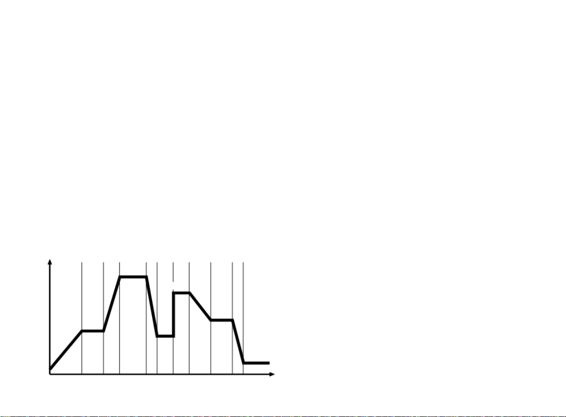
The Programmer function in Level P enables the instrument to control applications
needing Setpoint changes over time. Examples of this are Ramp changes where a gradual
Rate of change can be set, or Step changes which are instantaneous. These can be
separated by Soak periods during which the process is held at a constant value. Each
individual time interval of the program or Segment, together with it’s associated moving
setpoint value can be stored as a unique Program and for example be represented by the
diagram below.
Setpoint
Soak Step
Ramp
Time (Segments)
In addition to those settings that determine the segment profile, it is also necessary to set
program start values, together with the preferred ramp rate time units for each individual
program.
At the end of a sequence, a Program can be arranged to repeat (Loop), either a specified
number of Cycles, or continuously. Only one Loop can be included in a Program. When the
program is running, the Display indicates progress through the sequence of segments, and
can additionally be interrogated for further segment information.
It is also possible to CALL an already existing program as a sub program that can be
inserted as a segment of another program.
To speed up Program configuration, several Edit functions have been provided so that
individual Segments and Programs may be Deleted or Inserted, and an entire Program
may be Copied and then Pasted into another that it will replace.
For safety reasons, three modes of recovery from a power failure are available. These either
automatically Re-start the Program from the beginning, Continue it from where it stopped, or
Hold it waiting for a user re-start.
Either one or both of the two auxiliary outputs can be configured as Event outputs.
Engaging the Holdback feature will temporarily halt Setpoint ramping to allow the process
temperature to catch up should it deviate by more than a pre-set amount during a Ramp
segment.
To afford maximum programming flexibility, memory is allocated dynamically, and not pre-
allocated. This allows the user the freedom to configure a small number of long programs
or a larger number of shorter ones, up to the permitted maximum of 126 Segments per
program, and a limit of 31 Programs. Should these limits be exceeded, or the Programmer
memory become fully used, the display will read ProG FULL. Programs can be planned
using the Memory Allocation Table which details the memory requirements of individual
segment types. During configuration a check can be kept on memory usage by
interrogating the USEd feature of the display to give an instant reading of ‘percentage
memory used’.
Finally, once a program has been configured, it can be run from the run off/on/hold
controls in Level P, and in addition a quick access run/hold toggle is directly available from
the front panel.
The Programmer Functions List describes the full range of available Settings for each
Programmer Function together with their display mnemonic. The instrument is supplied
with a suite of Factory Settings for each Function. These are shown in bold type.
The Functions Map illustrates the relationship between the Functions and their Settings
and provides a guide to the Keying Operations required to navigate around the menu
when configuring or running a Program.
10 of 31
01/12

3.1 GETTING STARTED (PROGRAMMER)
New users should take a short time to study the following before starting to configure the
first program, and may wish to take on board the following tips and suggestions.
Program Mode Exit switch (ProG/Auto) Program Level 4.
This standard feature of the instrument causes automatic exit from program mode after
sixty seconds of Key inactivity. It is highly recommended that this setting be disabled and
changed to ProG/StAy to ensure that adequate time is available for making unfamiliar
adjustments.
Program Parameter List
Listing the required Program Settings and Parameter Values segment by segment beside
each Setting/Segment Number, and Program Display Mnemonic will reduce the risk of
programming mistakes during the learning period.
Memorise Basic Key Functions
Please become familiar with the following Menu Navigation principles
Hold both s and t for three seconds to enter or exit Program Mode.
Key either s or t to view Functions (follow horizontal arrows).
Key either Qs or Qt to view or change settings (follow vertical arrows).
Key Q and hold for three seconds to confirm Edit Functions.
Note: Factory Settings appear in the lower display in each of the Functions illustrated in
the Function Map.
Program configuration
When the PROGRAMMER function is entered at LEVL P, the Programmer is automatically
presented in Configuration Mode, and the instrument display can be used to access and
adjust the various FUNCTIONS.
3.2 Program Run Mode
To run a Program from
LEVL P
,
Press s once, then use Qs to select the required program number from the PrOG list.
Press s again once then use Qs to select the run/on option.
Press ts and hold for three seconds to exit configuration mode and run the program.
Run/Hold Toggle Feature
Press Qt and hold for 3 seconds to hold the program.
Press Qt again and hold for 3 seconds to run the program.
Note: Level P is ‘read only’ while a program is active.
To run a stopped program again press and hold the Qt to toggle RUN ON/OFF/ON again.
3.3 DISPLAY FUNCTIONS
Once the program is running, the display automatically tracks the progress of the program as it
indexes through it’s sequence of segments. When it concludes it’s final instruction, the upper
display alternates StoP with the Process Value and the lower display reverts to the instrument
SP1 Setpoint.
RAMP
The upper display alternates between SPr and the moving Process Value while the lower
display shows Target Setpoint. If Holdback is activated, the decimal point in the lower right
corner of the upper display will be illuminated.
SOAK
The upper display alternates between SoAK and the Process Value. The lower display
reads the Target Setpoint of the current segment.
STEP (not displayed)
As this involves an instantaneous change of the Target Setpoint, this segment occupies zero
time and the program immediately moves to the next segment. The lower display then
registers the new Target Setpoint, with the upper display alternating in either SPr or SoAK
mode according to the segment configuration.
HOLD
If the program is paused in HOLD, the upper display alternates between hoLd and the
Process Value, while the lower display indicates the Target Setpoint of the current
segment.
User Displays
With the program running, a further display function is available at any time.
Press and hold Q Display shows Program Number
Also press s once
Display shows Segment Number
Press s again Display shows number of loops completed if a loop function has
been set.
Press s again Upper display reads t.SP
Lower display shows moving Ramp setpoint
Or if in Soak Segment Upper display reads Sint (Soak interval)
Lower display reads remaining Soak time
Release Q
To return display to Program Run mode
11 of 31
01/12

3.4 EXAMPLE PROGRAM
TYPE
SPR
Temp
SPRR
105
T.SP
137
Ramp Function
Rate, 105 deg/hour
Target setpoint: 137 deg
TYPE TYPE
SOAK
STEP
SPR
LOOP
SPR
SINT
T.SP
45 85
Soak Function
Interval: 45 mins
Step Function
Target setpoint: 85 deg
TYPE TYPE TYPE
SPRR PCYC SPRR
55
1
105
T.SP T.SP
30 137
TYPE TYPE TYPE
SOAK
STEP
SPR
SINT
T.SP
SPRR
45 85 55
T.SP
30
Ramp Function
Rate, 55 deg/hour
Target setpoint: 30 deg
STOP
30
Loop Function
Number of repeat
program cycles: 1
SEG SEG SEG SEG SEG SEG SEG SEG SEG
1 2 3 4 5 1 2 3 4
Time
12 of 31
01/12

3.5 PROGRAMMER FUNCTION MAP
START HERE
Press and hold
t s
for 3 seconds
ENTER
PROGRAM
TUNE
OFF
t
PROG
ADD
Paste only appears
after a program is
copied
Copies the
selected
To add new program
program,
press s once
Program
RUN
s editing
OFF
functions.
Insert
t
Program
EDIT
PSTE
EDIT
COPY
EDIT
INS
Q
3 secs
Q
3 secs
Q
3 secs
SURE SURE
PROG
Q s
Q
NO
YES
3 secs
3
Program 1 has
been copied to
PROG
program 3
A copy of program 1 can be
1 pasted into another program
Another program has been Program 3has been
PROG
inserted into PROG 2
deleted. Display
2 re-numbering existing shows next program
PROG 2 to 3
down from top of list
LEVL
1
Q t
Add new
programs at
top of existing
menu
To viewexisting
PROG
editing
3 functions.
Delete
Program 3
now appears Hold the
in list program at
current position
PROG
2 Start program when ‘on’
selected. This locks
other options out
EDIT
SURE
Q
Q s
DEL
NO
3 secs
Hold the
program at
RUN
FAIL
the point it
HOLD
stopped
HOLD
Continue the
program
RUN
from where
FAIL
it stopped
ON
CONT
SURE
PROG
Q
YES
2
3 secs
ST.V
SPRU
SP
60 S
Options: start
program at main Options:
If COMMS option
fitted, LEVEL C
appears between
programs 1 to 31
or full?
Q s Program
‘off’ state
Reset the
Q s program at Q s
beginning
SP or process hours
minutes
variable Q s Q s
LEVEL P and LEVEL A
LEVL
C
LEVL
P
Q t
LEVL
A
PROG
s s
1 Select the required
program number.
Q t Default: 1
USED
0 Memory used (%)
RUN
FAIL
s s
OFF RSET
PV
HOUR
Select program mode Powerfailure recovery
of operation
position
Default: off Default: reset
ST.V
SPRU
s s
Select the starting point of Rampratetime units
program after power up adjustment
Default: PV Default: hour
13 of 31
01/12

SEG
ADD
Insert new
segment in
the menu
Delete a
segment
Event
To add new
output
segments
press s once
TYPE
Call up
s another
SPR
program
t
EDIT
INS
EDIT
DEL
TYPE
E,OP
TYPE
CALL
energise and de-energise
for all combinations of
SP2 & SP3.
Q
3 secs
Q
3 secs
Event output options
SEG
New segment now
inserted into 2. Old
2 segment 2 becomes 3
SURE SURE
SEG
Segment 3
Q s
Q
deleted
NO
YES
2
3 secs
Returns to
Define the program
number called
SEG
Default: none
SUB.P
NONE
Set Numbers of
re-cycles 1 to 999 unless
full. Or continuous
E.OP
2D3E
E.OP
2E3E
E.OP
2E3D
E.OP
2D3D
E.OP
3E
Add new
segments at
top of existing
list
To view existing
segments 1 to 126
or full?
SEG
Program
TYPE
3 re-cycles
LOOP
Segment 3
now appears
in menu
TYPE
Step
STEP
SEG
2
TYPE
Soak
SOAK
Q s
Ramp
Q s
SEG
TYPE
1 s
SPR
PCYC
1
Soak time in minutes
or continue
Default: 10
SINT
10
Important note
Up s button
must
be
used after selecting the
segment type to
confirm it’s selection
SPRR
s s
100
Default: 1
‘Hold back band
size adjustable
0.1 to 150 units
T.SP
HB.V
9999 150
Q s Q s
T.SP
HB.V
s
0.0
OFF
E.OP
3D
E.OP
2E
E.OP
2D
Q s
E.OP
s s
NONE
Set the segment to be To select operational Adjusts ramp Target set point adjustable ‘Hold back’ this function only Event output - options only
adjusted mode of each segment rate overthe unit’srange appears forrampoperational appear when SP2A or SP3A
Default: 1 Default: Ramp Default: 100
Default: Current main SP
once a value is set modes set to E.OP
Default: off Default: de-energise
14 of 31
01/12

3.6 FUNCTION LIST (LEVEL P) PROGRAMMER
LEVEL P
LEVL P
Access Level P from Level 1. Press and hold Q t
Function
Sub-functions Settings [Factory settings] shown
in brackets
Press s or t to change
Press Q s or Q t to change
TyPE Define segment type SPr Ramp to next target setpoint
Function
Press s or t to change
ProG Program number
run
Run Program
Fail Power failure recovery mode
St.V Program start value
SPru Ramp rate time units
SEG Segment number
Settings [Factory settings] shown in brackets
Press Q s or Q t to change
[1] Add new programs (1 to 31)
[oFF] Program not running
on Run program
hoLd Pause program
Edit dEL Delete program v
Edit inS Insert new program
Edit CoPy Copy another program
Edit PStE Paste copied program
[rSEt] Reset to program start
Cont Continue from interruption
hoLd Hold at interruption (User re-start)
[PV] Process value
SP Setpoint value
[hour] Ramp rate adjust in hours
60 s Ramp rate adjust in minutes
[1] Add new segments (1 to 126) k
SPrr [100] Setpoint ramp rate Units per
hour/minute (0-9990) (as set at
Spru above)
t.SP (Segment target setpoint)
adjustable over instrument’s
configured range
hb.u Hold back [oFF] sets the
permitted band size for the
measured value to deviate from
the ramp setpoint before the
program is ‘held back’ waiting for
the measured value to catch up.
(0.1 to 150 units)
SoAK Hold setpoint for pre-set time [10]
Sint Soak time, adjust in minutes
(cont.-1440) x 0.1
StEP Step to new target setpoint (Set
tSP as above)
LooP Re-cycle program
PCYC [1] Set number of program loops
up to 999, or continuous loop
k
CALL Call up another program by
number to import into this
program
Sub.P (nonE) Number of Program called
at Call above
Edit dEL Delete segment v
Edit inS Insert new segment
v Deleting a Program automatically re-numbers those programs with higher numbers
k Until memory full. See page 14 for further explanation.
15 of 31
01/12

Function
Settings [Factory settings] shown in brackets
Press s or t to change
Press Q s or Q t to change
E.oP Event output [nonE] Function can be applied to each
segment independently to trigger
an output at the start of that
segment for the duration of that
segment. Setting blocked unless
either or both outputs SP2A or
SP3A have been configured as an
Event Output in Level 2 or Level A
respectively.
2d SP2A de-energised to mark event
2E SP2A energised to mark event
3d SP3A de-energised to mark event
3E SP3A energised to mark event
2d.3d SP2A and SP3A de-energised to
mark event
2E.3d SP2A energised SP3A de-energised
to mark event
2E.3E SP2A and SP3A energised to mark
event
2d.3E SP2A de-energised SP3A energised
to mark event
To Return to:
LEVL P
Press and hold t
To Read % Programmer memory used:
USEd
Press Q and t together in LEVL P / ProG 1
1-100%
3.7 Memory Allocation Table
Segment type Memory required
Ramp
4 Bytes
Ramp with Holdback
5 Bytes
Soak
2 Bytes
Step
3 Bytes
Loops (1-3)
1 Byte
Loops (4+)
2 Bytes
Call
1 Byte
Event Output 1 Byte
Program Header 1 Byte
Maximum capacity: 351 Bytes
31 Programs
126 Segments
Examples:
1. 1 program of 58 Ramps and 58 Soaks 349Bytes
2. 4 programs of 14 Ramps and 14 Soaks 340 Bytes
3. 31 programs of 2 Ramps and 1 Soak 341 Bytes
4. 2 programs of 10 Ramps, 10 Soaks, 2 Steps and 1 loop 136Bytes
3.8 Memory Full Indication
Should the programmer memory capacity be reached during program configuration, the
display will show ‘FULL’
16 of 31
01/12

3.9 PROGRAMMING EXAMPLES
3.10 Program Edit Function
Make copy of Program 1 and paste as
EDIT
new Program 2
PSTE
ADD
RUN
PROG(next)
OFF
SURE
YES
Arrows drawn thus
signify several key
operations
SURE
Q
3 secs
NO
Q
3 secs
PROG
Program 1
now pasted
2 as Program 2
KEY
Programmer functions
shown as white
characters on black
background have
Default settings
EDIT
COPY
Q
3secs
PROG
RUN
1
OFF
PROG
1
SEG
ADD
SEG
5
SEG
4
SEG
3
SEG
2
KEY t OR s TO VIEW FUNCTIONS
Program Segment Configuration
See Program 3 illustrated on page 10
TYPE
PCYC
LOOP
1
TYPE
SPRR
T.SP
SPR
55 30
TYPE
T.SP
STEP
85
TYPE
SINT
SOAK
45
PROG
Program settings for functions:
SEG
TYPE
SPRR
T.SP
HB.V
E.OP
run
;
FAiL
;
St.U
and
SPru
3 not shown, are all set to Default 1
SPR
10 S
137
OFF
NONE
17 of 31
01/12

3.11
Quick Programming Guide
DUAL TEMPERATURE CYCLING WITH LIGHTS ON
In this program we will set the first temperature at 25ºC for a period of twelve hours
with the lights on and the second temperature of 15ºC for a period of twelve hours with
the lights off. This program will also run continuously.
Press and hold both ▲and ▼buttons for 3 seconds
Display will read LEUL
P
Press ▲button, display reads Prog
Add
Press ▲button until display reads Stu
Pu
Press and hold * and press ▲, display reads Stu
SP
Press ▲button until display reads SEG
Add
Press ▲button until display reads type
SPR
Press and hold * and press ▲button until display reads type
Step
Press ▲button until display reads t.SP
0.0 (current Set temp.)
Press and hold * and press either ▲or ▼button until set-point is reached
25ºC
Press ▲button until display reads EOP
3D
Press and hold * and press ▲until display reads EOP
3E
Press ▲button, display reads SEG
1
Press and hold * and press ▲button, display reads SEG
Add
18 of 31
01/12

Press ▲button, display reads type
SPR
Press and hold * and press ▲button until display reads type
SOAK
Press ▲button, display reads si.nt
10.0
Press and hold * and press ▲or ▼button to change time in minutes you wish
program to run, display reads si.nt
720
Press ▲button, display reads EOP
3D
Press and hold * and press ▲button, display reads EOP
3E
Press ▲button, display reads SEG
2
Press and hold * and press ▲button, display reads SEG
Add
Press ▲button, display reads type
SPR
Press and hold * and press ▲button until display reads type
Step
Press ▲button, display reads t.SP
0.0 (current set-point)
Press and hold * and press either ▲or ▼button until set-point is reached
15ºC
Press ▲button, display reads EOP
3E
Press and hold * and press ▲button until display reads EOP
3D
Press ▲button, display reads SEG
3
Press and hold * and press ▲button, display reads SEG
Add
Press ▲button, display reads type
SPR
Press and hold * and press ▲button until display reads type
SOAK
Press ▲button, display reads si.nt
10.0
19 of 31
01/12

Press and hold * and press ▲or ▼button to change time in minutes you wish
program to run, display reads si.nt
720
Press ▲button, display reads EOP
3D
Press ▲button, display reads SEG
4
Press and hold * and press ▲button, display reads SEG
Add
Press ▲button, display reads type
SPR
Press and hold * and press ▲button until display reads type
LOOP
Press ▲button, display reads PCYC
1
Press and hold * and press ▼button until display reads PCYC
Cont
Press ▲button, display reads EOP
3D
Press ▲button until display reads SEG
5
Press and hold both the ▲and ▼buttons together for 3 seconds to finish the
programming. The display will return to show Actual and Set-point temperatures.
To Run Program
Press both ▲and ▼buttons together for 3 seconds, display reads LEUL
P
Press ▲button until display reads run
Off
Press and hold * and press ▲button, display reads run
On
Press both ▲and ▼buttons together for 3 seconds. The program will now run
20 of 31
01/12
This manual suits for next models
17
Table of contents
Other LMS Accessories manuals
Popular Accessories manuals by other brands

Huawei
Huawei iSiteC BTS3601C-800 user manual

Vega
Vega VEGAFLEX 86 operating instructions

Silvercrest
Silvercrest SPB 2.600 B1 operating instructions

Bühler technologies
Bühler technologies EGK 2-19 Brief instructions

Optimum
Optimum LP-0007 operating instructions

OJ Electronics
OJ Electronics MICROLINE OTD2 instructions