manuals.online logo
Brands
  1. Home
  2. •
  3. Brands
  4. •
  5. Vortec
  6. •
  7. Accessories
  8. •
  9. Vortec VORTEX COOLER 727SS Use and care manual

Vortec VORTEX COOLER 727SS Use and care manual

OPERATION & SAFETY
INSTRUCTIONS
10125 Carver Road, Cincinnati, OH 45242
Phone: 513-891-7474 • Fax: 513-891-4092
Toll Free: 800-441-7475
www.vortec.com • techsuppor[email protected]
Please read all instructions BEFORE
attempting to use this product
IMPORTANT
LIT
OPERATION & SAFETY
INSTRUCTIONS
Please read all instructions BEFORE
attempting to use this product
IMPORTANT
LIT0161
VORTEX COOLERTM - UL TYPE 4X
Models 727SS, 727SS-15H, 727SS-35H,
737SS, 747SS, 787SS, 797SS,
787SS-35H, 797SS-35H
(Includes all BSP versions of models listed above)
FILTER AND REPLACEMENT PART ITEM NUMBERS
Vortec Model Oil Removal Filter Valve & Thermostat Kit
(120 VAC)
Valve & Thermostat Kit
(240 VAC)
Replacement Generator Kits
(5 pc)
727SS-15H, 737SS 701S-48 721T-70 721T-80 208GK-15H
727SS, 787SS 701S-48 721T-70 721T-80 208GK-25H
727SS-35H, 787SS-35H 701S-54 721T-100 721T-110 208GK-35H
747SS 701S-48 - 721T-80 208GK-15H
797SS 701S-48 - 721T-80 208GK-25H
797SS-35H 701S-54 - 721T-110 208GK-35H
TABLE 1: FILTER RECOMMENDATIONS
TABLE 2: DETERMINING COMPRESSED AIR LINE SIZE
1. Calculate total product compressed air consumption (SCFM, SLPM).
2. Determine length of compressed air line required for connection to main supply.
3. Locate pipe length in left column and read to the right to nd the compressed air requirements.
4. Locate pipe size at top of column.
MAXIMUM AIRFLOW (SCFM) THROUGH PIPE AT 5 PSIG PRESSURE DROP (100 PSIG AND 70OF)
Pipe Length
(Feet)
Pipe Size (Nominal) - Schedule 40
1/4 3/8 1/2 3/4 1 1-1/4 1-1/2 2 2-1/2
10 29 65 120 254 480 978 1483 2863 4536
20 21 46 85 180 340 692 1049 2024 3208
30 17 37 70 147 277 565 856 1653 2619
40 15 32 60 127 240 489 792 1431 2268
50 13 29 54 114 215 437 663 1280 2029
60 12 26 49 104 196 399 606 1169 1852
70 11 25 46 96 181 370 561 1082 1715
80 10 23 43 90 170 346 524 1012 1604
90 10 22 40 85 160 326 494 954 1512
100 9 21 38 80 152 309 469 905 1435
MAXIMUM AIRFLOW (SLPM) THROUGH PIPE AT 0.3 BAR PRESSURE DROP (6.9 BAR AND 21OC)
Pipe Length
(Meters)
Pipe Size (Nominal) - Schedule 40
1/4 3/8 1/2 3/4 1 1-1/4 1-1/2 2 2-1/2
3 821 1840 3396 7188 13584 27677 42117 81023 128369
6 594 1302 2406 5094 9622 19584 29687 57279 90786
9 481 1047 1981 4160 7839 15990 24225 46780 74188
12 425 906 1698 3594 6792 13839 20999 40497 64184
15 368 821 1528 3226 6085 12367 18763 36224 57421
18 340 736 1387 2943 5547 11292 17150 33083 52412
21 311 708 1302 2717 5122 10471 15877 30621 48535
24 283 651 1217 2547 4811 9792 14829 28640 45393
27 269 623 113 2 2406 4528 9226 13980 26998 42790
31 255 594 1075 2264 4302 8745 13273 25612 40611
Rubber hose maximum airow rating: 1/2” I.D. rubber hose = 3/8” pipe; 3/4” I.D. rubber hose = 1/2” pipe
GENERAL SAFETY CONSIDERATIONS
WARNING: COMPRESSED AIR COULD CAUSE DEATH,
BLINDNESS OR INJURY
1. Do not operate a Vortex Cooler at compressed air
pressures above 150 psig (10.3 Bar).
2. Do not operate at line temperatures above 110oF
(43oC).
3. Avoid direct contact with compressed air.
4. Do not direct compressed air at any person.
5. When using compressed air, wear safety glasses
with side shields.
Avertissements pour refroidiseur Vortex NEMA 4X
Modèles 727SS, 727SS-15H, 727SS-35H, 737SS,
787SS, 787SS-35H, 747SS, 797SS et 797SS-35H (et
versions BSP):
ATTENTION! Pour maintenir la notation UL, cet appareil
doit être installé debout avec le bouchon argent vers le
haut.
ATTENTION! Les surfaces extérieures de l’appareil
peuvent être chaudes. Eviter le contact.
INTRODUCTION
A Vortex Cooler is designed to use ltered compressed air to
cool industrial cabinets without the use of any refrigerants.
An internal Vortex tube lowers the temperature and pressure
of the compressed air supplied to the enclosure. Hot air in the
cabinet is vented to the surroundings through a built in relief
valve in the Vortex Cooler.
Vortex Coolers can be used with or without electric
thermostats and solenoid valves.
COMPRESSED AIR SUPPLY
The compressed air supply must be ltered to remove water
and dirt using a 5 micron or smaller lter. Failure to use a
lter may cause clogging (and freezing) of the compressed
air paths inside the Vortec product. Filter recommendations
are given in Table 1.
Filter elements must be changed on a regular basis.
Frequency of change is determined by the condition of the
compressed air supply. Filters should be installed in the
compressed air supply line as close as possible to the Vortec
product.
The appropriate size of compressed air supply line should
be selected to ensure optimal performance of the Vortec
product. Please refer to Table 2 to determine what supply line
size is recommended for your application. Contact Vortec at
1-800-441-7475 for further assistance.
MAINTENANCE
Vortec Cooler systems have no moving parts and can be
disassembled for cleaning.
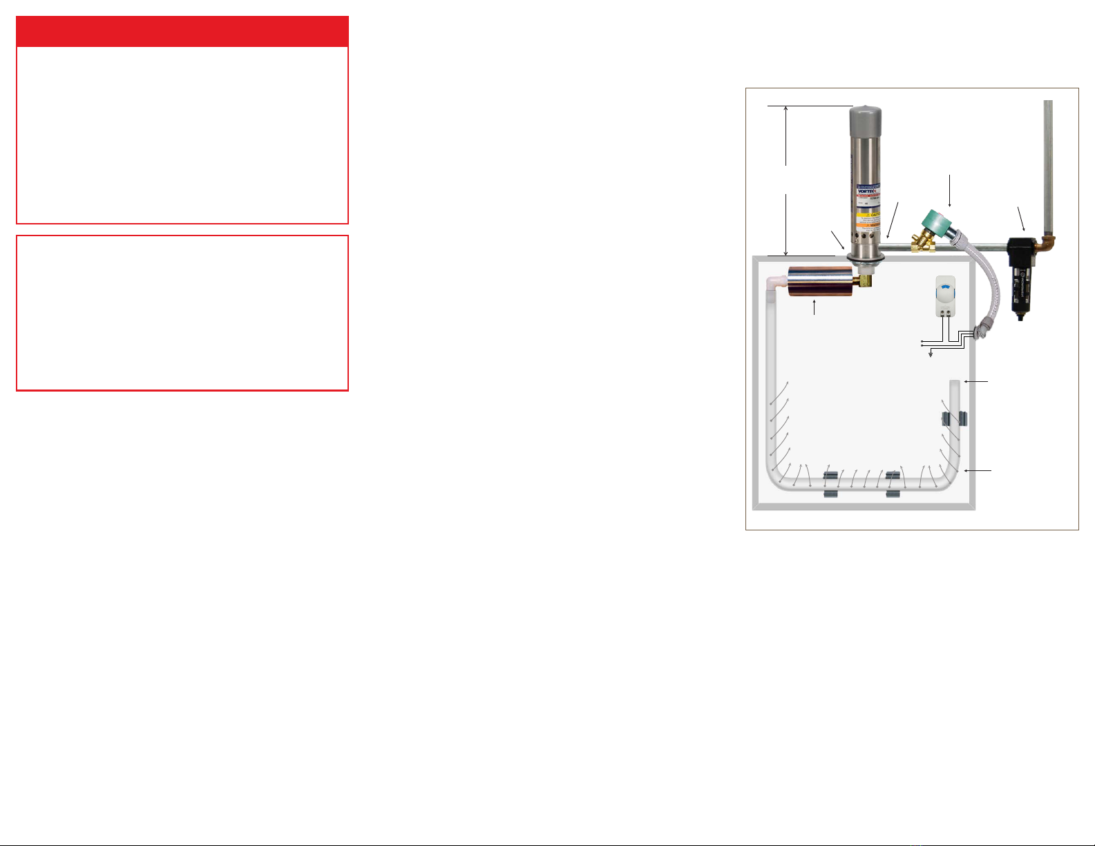
INSTALLATION AND OPERATION
To maintain the Type 4X rating, Type 4X Vortex Coolers
must be installed in a vertical orientation on a at horizontal
surface at the top of the cabinet.
Vents in the cabinets must be covered and sealed to ensure
cooling efficiency and to keep out ambient air. When a
thermostat is supplied with a Vortex Cooler system for Type
4X enclosures, the thermostat can be easily readjusted using
the temperature indicator dial. All wiring must be installed in
an approved conduit.
Installation procedures:
1. Cut a 1-15/16” (49 mm) (1-1/2” knockout size) hole in the
enclosure.
2. Insert Vortex Cooler into cut-out and secure with the
locknut.
3. Attach the cold air muffler to the outlet of the Vortex
Cooler.
4. Perforate the ducting kit with several 1/8” holes and
secure to interior of enclosure.
5. Attach the ducting kit to the cold air muffler.
6. Connect compressed air lter and/or valve and
thermostat, to the Vortex Cooler (wire thermostat directly
to solenoid valve). Install the compressed air lter and
solenoid valve as close as possible to the Vortex Cooler,
in a location where the temperature does not exceed
125oF (52oC).
8. Connect compressed air supply to the lter.
TROUBLESHOOTING
Insufficient airow may be caused by the following:
1. Undersized compressed air line size.
2. Compressed air pressure too low.
3. Partial or complete blockage of internal compressed air
path, due to dirt.
Insufficient cold air temperature may be caused by:
1. Compressed air line temperature too high.
2. Water vapor in the compressed air supply.
3. Loose cold cap. This may occur if not tightened properly
after disassembled for cleaning.
If trouble persists, please contact Vortec at 1-800-441-7475.
VORTEX COOLER ASSEMBLY
(Drawings shown below are not to scale)
Models 727SS, 737SS, 747SS, 787SS, 797SS, and variants
9-15/16
(252 mm)
Solenoid Valve
NEMA 4/4X
120VAC/60 Hz
110VAC/50Hz
1/4" NPT (F) Air Filter
Cold Air
1-15/16
Hole
Ducng Kit
Plug end of tubing
if holes are punched
in length of tubing
(as shown)
Cold Air
Muffler
Thermostat
120VAC/60Hz
110VAC/50Hz
LIMITED WARRANTY
Vortec compressed air products manufactured by ITW Air
Management will be replaced or repaired if found to be
defective due to manufacture defect within ten years from the
date of invoice. Refer to our website www.vortec.com for full
warranty details and limitations. ITW Air Management makes
no specic warranty merchantability or warrant of tness to a
particular purpose.

This manual suits for next models

8

Other Vortec Accessories manuals

Vortec VORTEX COOLER 7870 Use and care manual

Vortec

Vortec VORTEX COOLER 7870 Use and care manual

Vortec VORTEX COOLER 7875 Use and care manual

Vortec

Vortec VORTEX COOLER 7875 Use and care manual

Vortec Vest-L Use and care manual

Vortec

Vortec Vest-L Use and care manual

Popular Accessories manuals by other brands

IRROMETER WATERMARK Assembly instructions

IRROMETER

IRROMETER WATERMARK Assembly instructions

Lanberg SM01-DS01 user manual

Lanberg

Lanberg SM01-DS01 user manual

TeleAdapt PowerHub Mini installation guide

TeleAdapt

TeleAdapt PowerHub Mini installation guide

QC Industries PF26 Conveyors Installation, operation & maintenance instructions

QC Industries

QC Industries PF26 Conveyors Installation, operation & maintenance instructions

SIXTOL SX4010 Instructions for use

SIXTOL

SIXTOL SX4010 Instructions for use

SmartDHOME EcoDHOME Gas sensor installation manual

SmartDHOME

SmartDHOME EcoDHOME Gas sensor installation manual

Solectek 70MOB1 user guide

Solectek

Solectek 70MOB1 user guide

Style selections SS-7411 manual

Style selections

Style selections SS-7411 manual

Somogyi Elektronic HOME THO SERIES instruction manual

Somogyi Elektronic

Somogyi Elektronic HOME THO SERIES instruction manual

Focusrite Scarlett 18i20 user guide

Focusrite

Focusrite Scarlett 18i20 user guide

Promatic Super Hawk operating instructions

Promatic

Promatic Super Hawk operating instructions

BOMANN VS 262 user manual

BOMANN

BOMANN VS 262 user manual

Waterpik Sidekick WF-04 quick start guide

Waterpik

Waterpik Sidekick WF-04 quick start guide

Carlon Wireless Chime Button Instruction guide

Carlon

Carlon Wireless Chime Button Instruction guide

HB Products HBLT manual

HB Products

HB Products HBLT manual

Philips HF3500 Quick start card

Philips

Philips HF3500 Quick start card

Aritech VE700AM Series Installation sheet

Aritech

Aritech VE700AM Series Installation sheet

Sartorius Combics 3 Series operating instructions

Sartorius

Sartorius Combics 3 Series operating instructions

manuals.online logo
manuals.online logoBrands
  • About & Mission
  • Contact us
  • Privacy Policy
  • Terms and Conditions

Copyright 2025 Manuals.Online. All Rights Reserved.