LNC LNC-T800 User manual

2008/4 Ver:V04.00.000 (4408110048)
LNC-T800
O
Op
pe
er
ra
at
to
or
r’
’s
s
M
Ma
an
nu
ua
al
l
Leading Numerical Controller
LNC Technology Co., Ltd.


LNC-T800
Table Of Contents
LNC Technology Co., Ltd. I
Table Of Contents
1CNC GROUP INSTRUCTION ................................................................. 1
1.1 Types of Operation Device ..............................................................................................................1
1.1.1 LCD Monitor.........................................................................................................................2
1.1.2 MDI Data Input Panel ..........................................................................................................2
1.2 Operation Device Introduction.........................................................................................................3
1.3 Screen and Fnction Instruction .......................................................................................................8
1.3.1 Alposition of the Display Screen..........................................................................................8
1.3.2 Functions of Each Function Group .................................................................................... 10
1.3.3 Absolute Coordinate screen ..............................................................................................17
1.3.4 Relative Coordiante Screen...............................................................................................18
1.3.5 Machine Coordinate Screen ..............................................................................................19
1.3.6 Handle Interrupt Screen.....................................................................................................20
1.3.7 Quit System .......................................................................................................................21
1.4 Program Function (PROG)............................................................................................................22
1.4.1 Current Program ................................................................................................................23
1.4.2 Background Program.........................................................................................................26
1.4.3 Program Checkup..............................................................................................................27
1.4.4 MDI ....................................................................................................................................28
1.4.5 DIRMNG ............................................................................................................................29
1.4.6 COMM. (RS232 Communiaction)......................................................................................44
1.5 Compensation Function (OFFSET)...............................................................................................49
1.5.1 WEAR:Tool Wear Compensation....................................................................................49
1.5.2 GEOM:Tool Shape Compensation..................................................................................52
1.5.3 SHIFT:Work Coordinate Offset .......................................................................................53
1.5.4 MACRO Variable ...............................................................................................................54
1.5.5 WORK:Workpiece Coordinate System ...........................................................................55
1.6 Graph Function (GRAPH) .............................................................................................................56
1.6.1 Function Introduction .........................................................................................................56
1.6.2 GRAPH ..............................................................................................................................56
1.6.3 SET ....................................................................................................................................57
1.7 Diagnosis Function (DGNOS) .......................................................................................................58
1.7.1 ALARM...............................................................................................................................58
1.7.2 SYSUPD :System Update..............................................................................................62
1.7.3 IOCSA................................................................................................................................75

LNC-T800
Table Of Contents
II LNC Technology Co., Ltd.
1.7.4 MLC2 .................................................................................................................................76
1.7.5 System Information............................................................................................................79
1.8 Software Panel function (SOFTPL)...............................................................................................80
1.9 PARAM ..........................................................................................................................................81
1.9.1 NC.SYS:System Parameter>..........................................................................................81
1.9.2 CHGUSR............................................................................................................................84
1.9.3 USROPT............................................................................................................................85
1.10 RESET ..........................................................................................................................................86
2LNC CONTROLLER OPERATION INSTRUCTION.............................. 87
2.1 Introduction of File Operation........................................................................................................87
2.1.1 Open File ...........................................................................................................................87
2.1.2 Copy File............................................................................................................................87
2.1.3 Delete File..........................................................................................................................88
2.1.4 Rename File ......................................................................................................................89
2.2 Program Edit .................................................................................................................................90
2.2.1 Program Edit......................................................................................................................90
2.2.2 Line Positioning .................................................................................................................90
2.2.3 Search for Word String ......................................................................................................90
2.2.4 Copy Data Segment ..........................................................................................................90
2.2.5 Delete Data Segment ........................................................................................................91
2.2.6 Teach Input ........................................................................................................................91
2.3 Manual Data Input (MDI) ...............................................................................................................92
2.4 Execution of Part Program ............................................................................................................92
2.5 Origin Return (HOME)...................................................................................................................92
2.6 Instruction on JOG Operation .......................................................................................................92
2.7 Instruction on MPG Operation.......................................................................................................92
2.8 Tool Wear Compensation Setting..................................................................................................93
2.9 Tool Length Compensation Setting ...............................................................................................93
2.10 Setting of Work Coordinate System (00, G54~G59).....................................................................94
2.11 Parameter Setting .........................................................................................................................95
2.12 Backup System Parameters..........................................................................................................95
2.13 Restore System Parameter...........................................................................................................96

LNC-T800
CNC Group Instruction
LNC Technology Co., Ltd. 1
1 CNC Group Instruction
1.1 Types of Operation Device
Ragarding the panel for the operators to proceed manipulation, it is divided into the MDI Data Input Panel and
the Operation Panel. MDI Data Input Panel’s major funtion is to let users edit or modify the program word by
word, and to set values. The Operation Panel is the control panel used to achieve kinds of manufacturing
needs, and it is composed of switches and buttons of many kinds of functions, and a Manual Pulse Generator
(handwheel, MPG), etc. The design of the Operation Panel may differ due to the differences between types of
machine tools, but this system provides a standard panel for machine tool manufacturers to utilize.

LNC-T800
CNC Group Instruction
2 LNC Technology Co., Ltd.
1.1.1 LCD Monitor
Figure 1.1-1 LCD Monitor
1.1.2 MDI Data Input Panel
A
F
K
P
U
X
B
G
L
Q
V
Y
C
H
M
R
W
Z
D
I
N
S
T
E
J
O
7
4
1
0
8
5
2
9
6
3
&
<
*
@
>
(
^
#
)
?+
!
_
Figure 1.1-2 MDI Data Input Panel
寶元科技
PS/2 Mouse port
PS/2 Keyboard port
LCD Switch
Sub function keys
Main function keys

LNC-T800
CNC Group Instruction
LNC Technology Co., Ltd. 3
1.2 Operation Device Introduction
Buttons shown on the LCD monitor and the MDI Data Input Panel can be divided into 4 types according to the
functions respectively:
(1). Major function button :
Right below the LCD are 6 horizontal buttons. They can be sued by users to input selections of functions
displayed at the lower side of the monitor.
Figure 1.2-1 6 major function buttons below the monitor
寶元科技
Major function buttons

LNC-T800
CNC Group Instruction
4 LNC Technology Co., Ltd.
(2). Minor function button:
After selecting the major function buttons, minor function contents will be displayed on the right side of
the monitor. Click the corresponding minor function button to make selection.
Figure 1.2-2 5 minor function buttons on the right side of the monitor
寶元科技
Minor function buttons

LNC-T800
CNC Group Instruction
LNC Technology Co., Ltd. 5
(3). Function group selection buttons:
Select from 8 types of function including POS, PROG, OFFSET, CAM, GRAPH, DGNOS, SOFTPL and
PARAM.
<POS> : Coordinate display screens
<PROG> : Program-related information screens
<OFFSET>: Tool compensation setting
<CAM> : Graphic-aided part program editing
<GRAPH> : Draw tool path
<DGNOS> : Display instant information of the diagnosis screen
<SOFTPL> : Software Panel switch
<PARAM> : Display parameter screen.
A
F
K
P
U
X
B
G
L
Q
V
Y
C
H
M
R
W
Z
D
I
N
S
T
E
J
O
7
4
1
0
8
5
2
9
6
3
;,.
&
<
*
@
>
(
^
#
)
?+
!
_
Function Group
selection buttons

LNC-T800
CNC Group Instruction
6 LNC Technology Co., Ltd.
(4). Letter and symbol buttons:
These letters, symbols and number buttons are mainly used to edit program and input data. Some of the
symbols are shrinked to the right lower corner of the buttons, and if need to use these shrinked symbols,
just hold the SHIFT button and click the symbol buttons.
(5). Edit buttons:
Use these buttons along with the cursor on the monitor to modify programs, set data and switch pages.
<SHIFT> : Accompany symbol and number buttons to input special symbols.
<INPUT> : Input button, confirm the input data.
<INS> : Switch between Insert Character and Replace Characer modes
<DEL> : Character cancellation button.
<HOME> : When editing program, move the cursor to the beginning of a line
<END> : When editing program, move the cursor to the end of a line
<SPACE> : Input a blank character
<CAN> : Cancel previous character
A
F
K
P
U
X
B
G
L
Q
V
Y
C
H
M
R
W
Z
D
I
N
S
T
E
J
O
7
4
1
0
8
5
2
9
6
3
;,.
&
<
*
@
>
(
^
#
)
?+
!
_
Symbol buttons

LNC-T800
CNC Group Instruction
LNC Technology Co., Ltd. 7
<PAGE↑> : Move to previous page
<PAGE↓> : Move to next page.
<→> : Cursor moves rightward
<←> : Cursor moves leftward
<↑> : Cursor moves upward
<↓> : Cursor moves downward
<RESET> : Reset system
A
F
K
P
U
X
B
G
L
Q
V
Y
C
H
M
R
W
Z
D
I
N
S
T
E
J
O
7
4
1
0
8
5
2
9
6
3
;,.
&
<
*
@
>
(
^
#
)
?+
!
_
Edit buttons
LNC-T800
CNC Group Instruction
8 LNC Technology Co., Ltd.
1.3 Screen and Fnction Instruction
There are 7 function groups in this controller. They are Coordinate (POS), Program (PROG), Compensation
(OFFSET), Graph (GRAPH), Diagnosis (DGNOS), Soft Panel (SOFTPL), and Parameter (PARAM). In this
manual,【 】is used to indicate the function buttons below and on the right side of the monitor, and < >
for buttons on the MDI Data Input Panel.
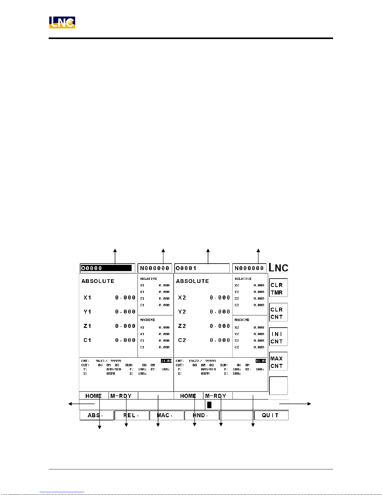
1.3.1 Alposition of the Display Screen
When switching groups in dual systems, both systems’ groups will be switched. The figure below is a screen
displaying simultaneous data of both systems, and on the left side of the screen (X1, Y1, Z1, C1) is System 1,
on the right side of the screen (X2, Y2, Z2, C2) is System 2. The position dedicated to System 1 and System 2
can be changed by Pr.4989.
The buttons only work on the currently working system. To know which the currently working system is,
distinguish from whether the cursor stays on position 1 or 3 in the figure below. When cursor stays on position
1, the currently working system is System 1; and when on position 3, the currently working system is System
2.
The screen introduction below is for the system data screens appear in the screen.
5
1 2 3 4
6 8 9 107
12
11

LNC-T800
CNC Group Instruction
LNC Technology Co., Ltd. 9
1: System 1 currently specified program name.
2: System 1 currently executed block.
3: System 2 currently specified program name.
4: System 2 currently executed block.
5: System 1 mode information.
6: System 1 machine status information.
7: System 1 alarm information (Alarm), warning information (Waring).
8: System 2 mode information.
9: System 2 machine status information.
10: System 2 alarm information (Alarm), warning information (Waring).
11: Simple information prompt area.
12: Input area.
Data of both systems can be displayed on the screen simultaneously or separately as shown in the following
figure:
LNC-T800
CNC Group Instruction
10 LNC Technology Co., Ltd.
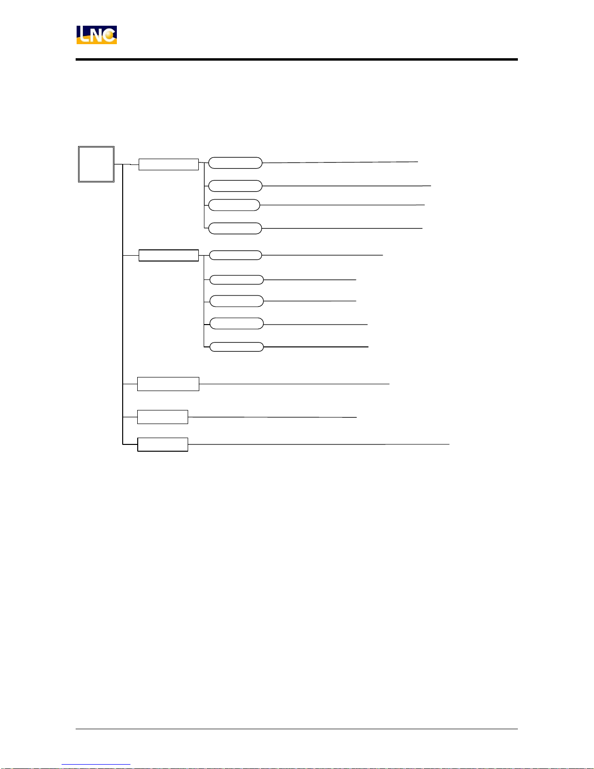
1.3.2 Functions of Each Function Group
Tree Diagram of POS Function Keys
ABSOLUTE
RELATIVE
MACHINE
POS
HND.
Show Mechanical coordinates
Set all relative coordinates to 0
Set relative coordinates of X axis to 0
Set relative coordinates of Y axis to 0
Set relative coordinates of Z axis to 0
Motion amount interpolated by handle
QUIT Quit the system
Set target parts count
Set operation time to 0
Set parts count to 0
Set initial parts count
CLR TMR
CLR CNT
INI CNT
MAX CNT
CLR.ALL
CLR.X
CLR.Y
CLR.Z
Set relative coordinates of Z axis to 0
CLR.C
Figure 1.3-1 Tree Diagram of POS Function Keys

LNC-T800
CNC Group Instruction
LNC Technology Co., Ltd. 11
Tree Diagram of PROG Function Keys
PROG
COMM.
MDI
PROCHK
DIRMNG
FGPROG
INS CYCL
EDITCYCL
LDEL
MARK
UN MARK
COPY
CUT
BIND
NEXT
NEXT
Copy the selected range
Move cursor to the designated line
Move cursor to the designated word
Insert MACRO
Edit MACRO
Delete the line pointed by cursor
Mark the selected range
Unmark the selected range
Paste the selected range
Cut the selected range
Open Teach In window
Open a file
Copy the selected file
Copy files from A to C
Copy files from C to A
Delete the selected file
Change the selected file name
Set default diretory
Show current program’s information
Download file via RS232
Upload file via RS232
Execute MDI command
COPY
COPYA>C
COPYC>A
DEL
REN
SETDIR
DOWNLOAD
UP LOAD
NEXT
COMM
SETT
File transmission main screen
Set RS232 protocol
NEXT
NET SET Set network connection
GOTO
WORDFIND
FILE
THINMODE
Figure 1.3-2 Tree Diagram of PROG Function Keys

LNC-T800
CNC Group Instruction
12 LNC Technology Co., Ltd.
Tree Diagram of OFFSET Function Keys
OFFSET ABS
SET ALL
INC
NORUNT
MINUNT
SET X
SET Y
SET Z
SET C
WEAR
WORK
SHIFT
Absolute input mode
Input unit: um
Input unit: mm
Incremental input mode
Local variable setup
Set mechanical coordinates of all axes
Set mechanical coordinates of X axis
Set mechanical coordinates of Z axis
Set mechanical coordinates of C axi
s
Set mechanical coordinates of Y axis
Coordinate system offset setup
ABS
INC
NORUNT
MINUNT
GEOM Absolute input mode
Input unit: um
Input unit: mm
Incremental input mode
#
@
MACRO
Global variable setup
Figure 1.3-3 Tree Diagram of OFFSET Function Keys

LNC-T800
CNC Group Instruction
LNC Technology Co., Ltd. 13
Tree Diagram of GRAPH Function Keys
GRAPH GRAPH
SET
Draw Tool Path
Set graphic drawing window
Figure 1.3-4 Tree Diagram of GRAPH Function Keys

LNC-T800
CNC Group Instruction
14 LNC Technology Co., Ltd.
Tree Diagram of DGNOS Function Keys
DGNOS
I/O
MLC2
SYSTEM
SYS UPD
ALARM Show system alarm
Show system version & debug message
Show system warning
Show system alarm/warning history
Show current I bit value
Show current O bit value
Show current C bit value
Show current S bit value
Show current A bit value
Show ladder diagram
Show current counter value
Show current R register value
Show current D register value
Show hardware diagnosis result
Enter System Upgrade page
Show system operation history
ALARM
WARN
HISMSG
LOGHST
OP LOG
I BIT
O BIT
C BIT
S BIT
A BIT
LAD
CNT
REG
DRG
Show current timer value
TMR
GBL
H.D
Show system data
Figure 1.3-5 Tree Diagram of DGNOS Function Keys

LNC-T800
CNC Group Instruction
LNC Technology Co., Ltd. 15
Tree Diagram of SOFTPL Function Keys
Figure 1.3-6 Tree Diagram of SOFTPL Function Keys

LNC-T800
CNC Group Instruction
16 LNC Technology Co., Ltd.
Tree Diagram of PARAM Function Keys
Figure 1.3-7 Tree Diagram of PARAM Function Keys
Table of contents


