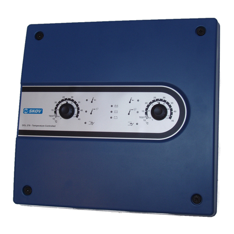
Norac UC7 User manual

Rogator–ActiveWingRoll(2018+)
(900,1100,1300)
UC7BoomHeightControlSystem
InstallationManual

Copyright2019byNORACSystemsInternationalInc.
ReorderP/N:UC7‐BC‐RG12A‐INSTRevE(Rogator–ActiveWingRoll(2018+)(900,1100,1300))
NOTICE:NORACSystemsInternationalInc.reservestherighttoimproveproductsandtheirspecificationswithoutnoticeandwithouttherequirementtoupdate
productssoldpreviously.Everyefforthasbeenmadetoensuretheaccuracyoftheinformationcontainedinthismanual.Thetechnicalinformationinthismanual
wasreviewedatthetimeofapprovalforpublication.

WWW.NORAC.CA
PRECISIONDEFINED
Contents
1
Introduction..........................................................................................................................1
2
TechnicalSpecifications........................................................................................................2
3
PartsOverview......................................................................................................................3
4
Pre‐InstallationChecklist.......................................................................................................9
5
HydraulicInstallation...........................................................................................................10
6
UltrasonicSensorInstallation..............................................................................................18
7
ElectronicInstallation..........................................................................................................22
8
WingRollCylinderAirBleedProcedure..............................................................................27
9
SoftwareSetup....................................................................................................................28
10
CableSchematics.................................................................................................................29

WWW.NORAC.CA
PRECISIONDEFINED
Page1
Visitwww.solutions.norac.caformoresystem
installationandtroubleshootinginfo.
1 Introduction
CongratulationsonyourpurchaseoftheNORACBoomHeightControlSystem.Thissystemismanufactured
withtopqualitycomponentsandisengineeredusingthelatesttechnology to provide operating reliability
unmatchedforyearstocome.
Whenproperlyusedthesystemcanprovideprotectionfromsprayerboomdamage,improvesprayerefficiency,
andensurechemicalsareappliedcorrectly.
Please take the time to read this manual completely before attempting to install the system. A thorough
understandingofthismanualwillensurethatyoureceivethemaximumbenefitfromthesystem.
Your input can help make us better! If you find issues or have suggestions regarding the parts list or the
installationprocedure,pleasedon’thesitatetocontactus.
Everyefforthasbeenmadetoensuretheaccuracyoftheinformationcontainedinthismanual.Allparts
suppliedareselectedtospeciallyfitthesprayertofacilitateacompleteinstallation.However,NORACcannot
guaranteeallpartsfitasintendedduetothevariationsofthesprayerbythemanufacturer.
Pleasereadthismanualinitsentiretybeforeattemptinginstallation.

WWW.NORAC.CA
PRECISIONDEFINED
Page2
Visitwww.solutions.norac.caformoresystem
installationandtroubleshootinginfo.
2 TechnicalSpecifications
CANICES‐3(A)/NMB‐3(A)
ThisClassAdigitalapparatuscomplieswithCanadianICES‐003.
PursuanttoEMCDirective–Article9,thisproductisnotintendedforresidentialuse.
Table1:SystemSpecifications
SupplyVoltage(rated) 12VDC
SupplyCurrent(rated) 10A
HydraulicPressure(maximum) 3300psi
BaudRate 250kbps
OperatingTemperatureRange 0°Cto80°C

WWW.NORAC.CA
PRECISIONDEFINED
Page3
Visitwww.solutions.norac.caformoresystem
installationandtroubleshootinginfo.
3 PartsOverview
3.1. ElectronicInstallationOverview
Figure1:ElectronicInstallationOverview

WWW.NORAC.CA
PRECISIONDEFINED
Page4
Visitwww.solutions.norac.caformoresystem
installationandtroubleshootinginfo.
3.2. HydraulicPlumbingSchematic
Figure2:HydraulicPlumbingSchematic

WWW.NORAC.CA
PRECISIONDEFINED
Page5
Visitwww.solutions.norac.caformoresystem
installationandtroubleshootinginfo.
3.3. ListofParts
Item PartNumber Name Quantity
B05 44706‐01 KITCABLETIEBLACK10PCS21IN150PCS7.5IN 2
B07 44749 BRACKETWRC80MMV1 1
B11 44695‐4 MOUNTINGBRACKETUC3SENSOR6INLG 1
B12 411275 BRKT,MTGSENSORLPEXTRIGHT 2
B13 411276 BRKT,MTGSENSORLPEXTLEFT 2
B15 50920 MOUNTINGBRACKET90DEGMANIFOLD509 1
B20 44971‐01 SENSORMOUNTINGBRACKETLOWPROFILE16GA‐NOMOUNTINGHARDWARE 4
C01 43220‐0.5 CABLENETWORK14AWG0.5M 3
C03 43220‐05 CABLENETWORK14AWG5M 2
C04 43220‐01 CABLENETWORK14AWG1M 1
C05 43210‐15 CABLENETWORK18AWG15M 4
C10 50130‐01 CABLEVALVE4‐PINDTTO2‐PINDT 3
C11 50120‐01 CABLETEMPERATUREPROBE 1
E01 50000 HCM1MODULE 1
E07 50300 MAXSENSOR 5
E08 50200 CANBUSREPEATER 1
E10 43760 NETWORKCOUPLER3‐WAY 3
E11 43765 NETWORKCOUPLER8‐WAY 1
E12 43764 NETWORKCOUPLER2‐WAY 2
E20 43764T NETWORKCOUPLER2‐WAYWITHTERMINATOR 4
H01 44863‐47 HOSEASSEMBLY122R2‐06175INL6FORX6FORX 1
H02 44863‐25 HOSEASSEMBLY122R2‐06136INL6FORX6FORX 1
H03 44863‐48 HOSEASSEMBLY122R2‐0640INL6FORX906FORX 3
H04 44863‐46 HOSEASSEMBLY122R2‐0640INL6FORX908FORX 1
H06 44863‐31 HOSEASSEMBLY122R2‐06106INL6FORX6FORX 4
H10 44865‐54 HYDRAULICSFITTINGKIT‐RG6 1
H11 44865‐75 HYDRAULICSFITTINGKIT‐AWR1 1
H12 44868 ACCUMULATOR10CUINCH,0.161L,900PSI 2
H13 44862‐18 HOSEASSEMBLY122R2‐0418INL6FORX6FORX 2
H14 44917 COUPLINGHYD6MB‐6MORMACHINEDORB 2
H20 44981 WINGROLLCYLINDER80MMW/POSITIONSENSOR 1
H21 44792‐111 ROLLPOSITIONDAMPER40.86IARG 1
H22 44750‐10 HARDWAREMOUNTINGLINEARROLL‐ROGATORLTUPPER 1
H23 44750‐11 HARDWAREMOUNTINGLINEARROLL‐ROGATORLTLOWER 1
M02 UC7‐BC‐RG12A‐INST MANUALINSTALLATIONUC7ROGATOR‐ACTIVEWINGROLL120'(2012+) 1
M04 100594 BOLTHEXNCGR5PLTD1/2X1 2
M05 106706 MOUNTINGCLIPHCM1 2
M06 100868 NUTLOCKNYLONNCPLTD1/2IN 2
M07 106849 BUMPERRUBBER 2

WWW.NORAC.CA
PRECISIONDEFINED
Page6
Visitwww.solutions.norac.caformoresystem
installationandtroubleshootinginfo.
Item PartNumber Name Quantity
M08 106904
BOLT U 304SS .31-18 THD X 1.88 X 2.63
8
M09 106906 NUTLOCKNYLONSS3/8IN 24
M10 106905 BOLTCARRIAGESS3/8X1‐1/4 8
P01 106705 NETWORK4PINCAVITYPLUG 2
P02 106602 NETWORK12PINPLUG(A‐KEY)DT 1
P03 105882 NETWORK6PINPLUG 3
V01 50903 VALVEASSEM3STATIONCCPROPDT 1
3.3.1. MountingBracketsfor120’Boom
Iftheboomisanearly2012120’productionmodel,thelineardampermountingbracketsmaynothavebeen
installedatthefactory.Thefollowingmountingbracketsareneeded:
PartNumber Name Quantity
44750‐1 BRACKETMOUNTINGLINEARROLLROGATORLT‐UPPER 1
44750‐2 BRACKETMOUNTINGLINEARROLLROGATORLT‐LOWER 1
3.3.2. ToolsRequired
Thislistisintendedtobeaguidelineforwhatisrequiredforinstallation.Additionaltoolsmayberequiredor
mayworkbetter.
SAEWrenches(sizes7/16"to1")
Side‐CuttingPliers(forcableties)
PowerDrill
5/8"DrillBit
TapeMeasure
CenterPunchandSmallHammer(Optional)

WWW.NORAC.CA
PRECISIONDEFINED
Page7
Visitwww.solutions.norac.caformoresystem
installationandtroubleshootinginfo.
3.3.3. HydraulicFittingKitDetails(P/N:44865‐54)
Item PartNumber Name Quantity Picture
F02 104586 TEEADAPTER‐6FORXR6MORT 3
F03 104885 TEEADAPTER‐8FORXR8MORT 2
F05 105327 MALETOFEMALEADAPTER‐12FORX6MOR 4
F06 106136 PLUG‐12MORP 2
F07 44917 MALEADAPTER‐6MB6MOR 4
F08 104369 PLUG‐6MBP 2
F09 44928 ORIFICEINSERT.047INONEWAY 2
F11 106137 MALEADAPTER‐10MB8MOR 1
F12 105338 TEEADAPTER‐12FORXR12MORT 1
F13 105732 MALETOFEMALEADAPTER‐8MOR12FORX 1
F14 104884 MALETOFEMALEADAPTER‐6MOR8FORX 1
Notallfittingsareusedforthisinstallation.
6 M B - 6 M OR X 90
SIZE IN
1/16TH'S
GENDER: MALE
OR FEMALE
90° ANGLE
SWIVEL
TYPE
GENDER
SIZE
TYPE:
B - ORB
J - JIC
OR - FLAT
FACE
P - PIPE
Fitting Name
Example:

WWW.NORAC.CA
PRECISIONDEFINED
Page8
Visitwww.solutions.norac.caformoresystem
installationandtroubleshootinginfo.
3.3.4. HydraulicFittingKitDetails(P/N:44865‐75)
Item PartNumber Name Quantity Picture
F12 44917 MALEADAPTER‐6MB6MOR 6
F13 104586 TEEADAPTER‐6FORXR6MORT 4
F14 104590 90DEGADAPTER‐6MOR6FORX90 9
Notallfittingsareusedforthisinstallation.
Donotusehighspeedpowertools/drillswheninstallinghardware.
TheuseofdielectricgreaseisnotrecommendedonanyNORACelectricalconnections.
ToensureallstainlesssteelhardwaredoesnotgallorseizeapplyalightcoatingofthesuppliedPermatex
Anti‐seizegreasetoallthreadedpartsuponinstallation.PermatexAnti‐seizelubricantispreferred,butother
similaranti‐seizeproductsmaybeused.
6 M B - 6 M OR X 90
SIZE IN
1/16TH'S
GENDER: MALE
OR FEMALE
90° ANGLE
SWIVEL
TYPE
GENDER
SIZE
TYPE:
B - ORB
J - JIC
OR - FLAT
FACE
P - PIPE
Fitting Name
Example:

WWW.NORAC.CA
PRECISIONDEFINED
Page9
Visitwww.solutions.norac.caformoresystem
installationandtroubleshootinginfo.
4 Pre‐InstallationChecklist
Thepre‐installchecklistisnecessarytochecktheexistingsprayerfunctionalitybeforetheinstallation.
1. Unfoldthesprayeroveraflat,unobstructedarea(i.e.nopowerlines…etc.).
2. Ensureallboom‐foldoperationsarefunctional(placeacheckmarkinboxesbelow).
3. Bringenginetofield‐operationalRPMandrecordbelow.
4. Recordthetime(seconds)ittakesforafullstrokeforallboom functions. To ensure repeatable
measurements,taketheaverageof3trials.
5. NotallsprayerswillhavethefunctionslistedbelowinFigure3.
Ensuretheboomhassufficienttravelsoitdoesnotcontactthegroundduringthesetests.
Figure3:Pre‐InstallBoomSpeeds

WWW.NORAC.CA
PRECISIONDEFINED
Page10
Visitwww.solutions.norac.caformoresystem
installationandtroubleshootinginfo.
5 HydraulicInstallation
Ensureallpressurehasbeenbledfromthesystembeforedisconnecting any lines or fittings. Hydraulic
pressurewillexistonthewingtiltcircuitsunlessthewingsarebeingsupportedbyothermeans.Thehydraulic
installationmaybeperformedwiththewingsintransportposition,restingonthegroundorwith thetilt
cylindersfullyextended.
Component failure due to oil contamination is not covered undertheNORACsystemwarranty.Itis
recommendedthataqualifiedtechnicianperformthehydraulicinstallation.
5.1. ValveBlockAssembly
1. Onacleansurfaceremovetheplasticplugsfromtheblock.
2. Installthe6MB‐6MOR(F07)fittingsintothe“P”and“T”ports.Tightento18ft‐lbs(24Nm).
3. Insertthetwoorifices(F09)intothe“B”portsofthetwostationsclosesttothe“P”and“T”portswiththe
notchfacingout.
4. Installthe6MB‐6MOR(F07)fittingsintothe“B”ports.Tightento18ft‐lbs(24Nm).
5. Installthe6MBP(F08)plugsintothe“A”portsofthetwostationsclosesttothe“P”and“T”ports.Tighten
to18ft‐lbs(24Nm).
6. Installthe6MB‐6MOR(*F12)fittingsintothe“A”and“B”portsofthe3
rd
stationoftheblock.Tightento
18ft‐lbs(24Nm).
Figure4:NORACValveBlockDetails

WWW.NORAC.CA
PRECISIONDEFINED
Page11
Visitwww.solutions.norac.caformoresystem
installationandtroubleshootinginfo.
5.2. ValveBlockMounting
1. AsuitablemountinglocationforthevalveblockisillustratedinFigure6.
2. Mountthemanifoldtothebracket(B15)usingthehardwaresupplied.
3. Attachthemountingbracketandvalvetothesprayerusingtheremininghardware.
4. Cutoffexcessboltorstudlengthifnecessary.
Figure5:ManifoldMountedtoBracket
Figure6:ValveBlockMounting

WWW.NORAC.CA
PRECISIONDEFINED
Page12
Visitwww.solutions.norac.caformoresystem
installationandtroubleshootinginfo.
5.3. WingRollCylinderMounting
1. Drilltwo(2)5/8inchholesinthecrossmemberbelowtherearcatwalkfourteeninches(14”)infromthe
rightsidetomountthewingrollcylindertotheboom.Theholesmustbespaced100mm(3.94”)apart.
2. Installthewingrollcylindermountingbracket(B07)ontotheboomframeusingthesuppliedhardware
(M4,M6).Tightenhardwareto60‐70ft‐lb(81‐95Nm).
3. Installfour(4)6MB‐6MORfittings(*F12)ontothe“1”,“2”,“3”,and“4”outerportsonthewingrollcylinder
(H20).
4. Mountthewingrollcylinder(H20)usingthesuppliedclamps.Installthewingrollcylinderwiththecable
endpointingtowardstheright‐handwing(whenlookingfromtherearofthesprayer).
Figure7:WingRollCylinderInstalledontheBoomFrame(whenlookingfromtherear)
Cylindermaynotbeexactlyasshown.
CableEnd

WWW.NORAC.CA
PRECISIONDEFINED
Page13
Visitwww.solutions.norac.caformoresystem
installationandtroubleshootinginfo.
5.4. LinearDamperInstallation
Beforecontinuing,tiltboththeleftandrightboomsuptothetopoftheirstroketomakeiteasiertorotate
theboom.
1. Beforeinstallingthelineardamper,thefactorysprings,dampersandrubberbumpersmustberemoved
fromthesprayer.TheLargeTreesprings,dampers,andbumpersareshowninFigure8andFigure9.The
SmallTreesprings,dampers,andbumpersareshowninFigure10.
2. ForLargeTreesprayers,installtheincludedrubberbumpers(M07)inplaceoftheoriginalones.
3. SmallTreesprayersdonotneedrubberbumpersinstalled.
Figure8:LargeTree‐AGCOFactorySpringandDamperLocation
Figure9:LargeTreeBumperLocation

WWW.NORAC.CA
PRECISIONDEFINED
Page14
Visitwww.solutions.norac.caformoresystem
installationandtroubleshootinginfo.
Figure10:SmallTree‐AGCOFactorySpring,Damper,andRubberBumperLocation
Figure11:LinearDamperMountingLocation–Small
TreewithFactoryMountingBrackets
Figure12:LinearDamperMountingLocation–Large
TreewithFactoryMountingBrackets
Figure13:LinearDamperMountingLocation–LargeTreewithAftermarketMountingBrackets

WWW.NORAC.CA
PRECISIONDEFINED
Page15
Visitwww.solutions.norac.caformoresystem
installationandtroubleshootinginfo.
4. Usingtheincluded1inchbolt,washers,andspacers,installtheendofthelineardamperwiththehydraulic
portontothetopmountingbracket.Thespacersmustbeinstalledasshown.
LargeTree(BoltInsertedfromRear)
SmallTree(BoltInsertedfromFront)
Figure14:TopRollPositionDamperMount
5. Usingtheother1inchboltandincludedspacers,attachtherodendofthedampertothebottommount.
Figure15:BottomRollPositionDamperMount
6. Tightenboththetopandbottomlineardampermountingboltsto500ft‐lbs(678Nm).
FlatWasher ThickSpacer ThinSpacer
FlatWasher ThickSpacers FlatWasher FlatWasher ThickSpacer ThinSpacer
FlatWasher

WWW.NORAC.CA
PRECISIONDEFINED
Page16
Visitwww.solutions.norac.caformoresystem
installationandtroubleshootinginfo.
5.5. HydraulicPlumbing
Fromthispointonintheinstallationtheboomswillbeinoperativeuntilthehydraulicsarefullyinstalled.
1. AftertheNORACvalveismounted,thehydraulichosesandfittingscanbeplumbed.Theplumbingforthe
hydrauliccircuitisshownschematicallyinFigure2.
2. DisconnectthetanklineattheRogatorvalveblockandinsertthe8FORXR‐8MORTtee(F03).
3. ConnectthestraightendofhoseH04tothetee(F03)androutetotheNORACvalveblock.
4. DisconnectthepressurelineattheRogatorvalveblockandinsertthe6FORXR‐6MORTtee(F02).
5. ConnectthestraightendofhoseH03tothetee(F02)androutetotheNORACvalveblock.
6. ConnecthoseH03tothepressureportandhoseH04tothetankportontheNORACvalveblock.
7. Disconnectandremovetheexistingleftandrightraiselines.
8. Insertthe12FORX‐6MORfitting(F05)intotheleftandrightraiseportsontheRogatorvalveblock.
9. Connecta6FORXR‐6MORTtee(F02)toeachF05fitting.
10. Connectthestraightendsoftwo(2)hosesH03tofittingsF02androutethehosestotheNORACvalve
block.
11. Connecta6FORXR‐6MORTtee(*F13)toeach“B”portonthefirsttwostationsontheNORACvalveblock.
12. ConnecthosesH03tothe*F13teefittingsonthecorrespondingleftandright“B”portsontheNORAC
valveblock.
13. Connecttheleftraiseline(H01)tothetee(F02)ontheleftportontheRogatorvalveblock.Connectthe
rightraiseline(H02)tothetee(F02)ontherightportontheRogatorvalveblock.Routethehosestothe
tiltcylinders.H01islongerthanH02sincetheNORACvalveblockisnormallylocatedontherightsideof
thesprayer.
14. ConnectH01andH02tothecylindersusingthe12FORX‐6MORfittings(F05).
15. Theexistinglowerlinesdonotneedtobemodified.LeavetheselinesconnectedtotheRogatorvalve
block.
16. ConnecthosesH06tothetees(*F13)onthe“B”portsontheNORACvalveblock.
17. Installfour(4)6MOR‐6FORX90fittings(*F14)ontothe*F12fittingsoneachportonthewingrollcylinder
(H20).

WWW.NORAC.CA
PRECISIONDEFINED
Page17
Visitwww.solutions.norac.caformoresystem
installationandtroubleshootinginfo.
18. Installtwo(2)6FORXR‐6MORTtees(*F13)ontothe*F14fittingsonthe“1”and“2”portsofthewingroll
cylinder(H20).
19. ConnecthoseH06fromtheright“raise”linetothe*F13teeonthe“2”portonthewingrollcylinder(H20).
20. ConnecthoseH06fromtheleft“raise”linetothe*F13teeonthe“1”portonthewingrollcylinder(H20).
21. ConnecthoseH06betweenthe“3”portonthewingrollcylinder(H20)andthe“B”portonthe3
rd
station
oftheNORACvalveblock.
22. ConnecthoseH06betweenthe“4”portonthewingrollcylinder(H20)andthe“A”portonthe3
rd
station
oftheNORACvalveblock.
23. ConnecthosesH13tothefreeendsofthe*F13teesonthe“1”and“2”portsofthewingrollcylinder.
24. ConnecttheotherendofhosesH13totheaccumulators(H12)using6MB‐6MORfittings(H14).
Figure16:AccumulatorInstallationLocation(LookingfromAbove)
Startupthesprayerandtestthesprayer’sfunctionality.Unfoldtheboomsandraise/lowereachboomand
themainsection.Ensurethattherearenoleaks.
Accumulators(H12)
WingRollCylinder
–CableEnd
Other manuals for UC7
4
Table of contents
Other Norac Control System manuals
Norac
Norac UC5 Can Bus User manual
Norac
Norac UC4 Total Control User manual
Norac
Norac UC4.5 User manual
Norac
Norac UC5 MAX User manual
Norac
Norac UC5 Topcon X30 User manual
Norac
Norac UC5 Topcon X30 User manual

Norac
Norac UC5 Topcon X30 User manual

Norac
Norac UC5 Topcon X30 User manual

Norac
Norac UC5 HD12 User manual
Norac
Norac UC4 Plus Rogator 64 Series User manual
Norac
Norac UC4+ User manual
Norac
Norac UC5 Rogator 600 User manual
Norac
Norac Case 44 Series User manual

Norac
Norac UC4.5 User manual
Norac
Norac UC4+ Apache 2010+ User manual
Norac
Norac UC4.5 User manual
Norac
Norac UC7 User manual

Norac
Norac UC4+ User manual

Norac
Norac UC7 User manual

Norac
Norac UC5 Topcon X30 User manual

