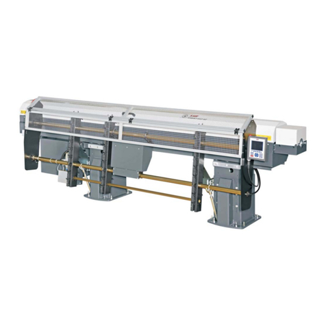
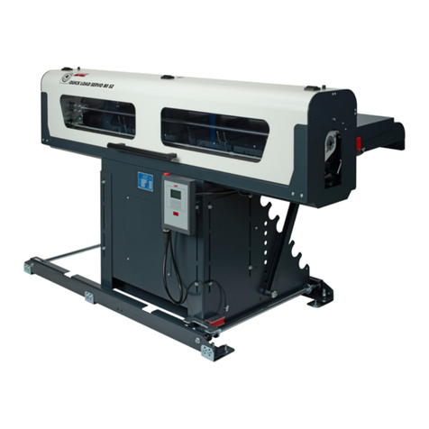
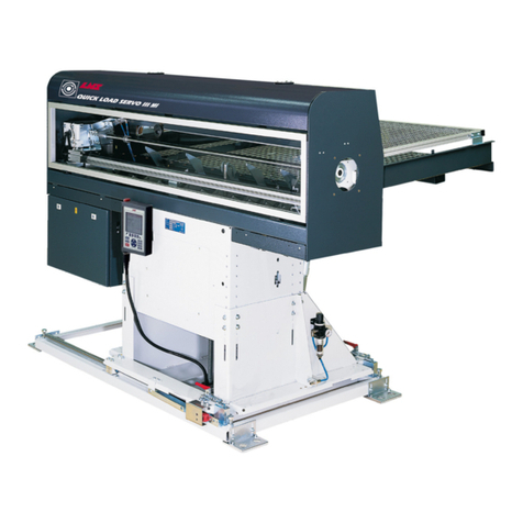
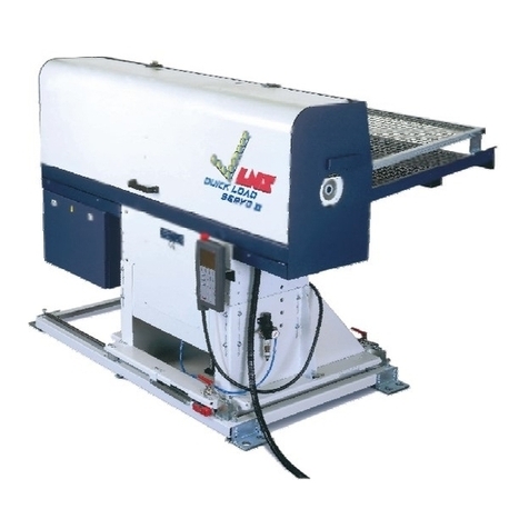
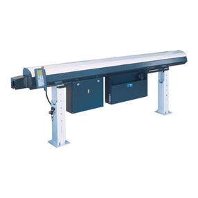
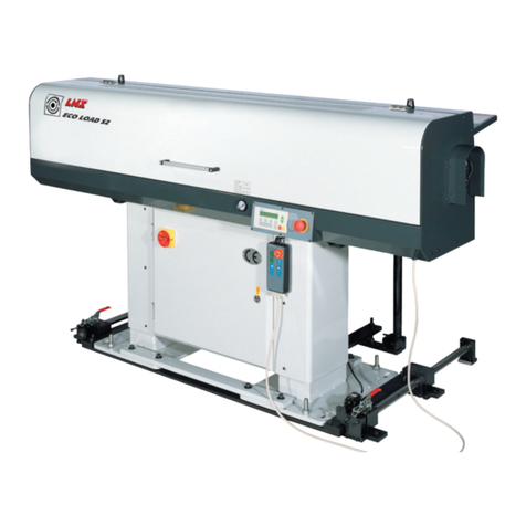
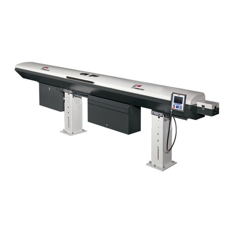
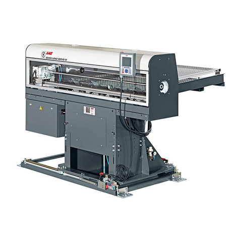
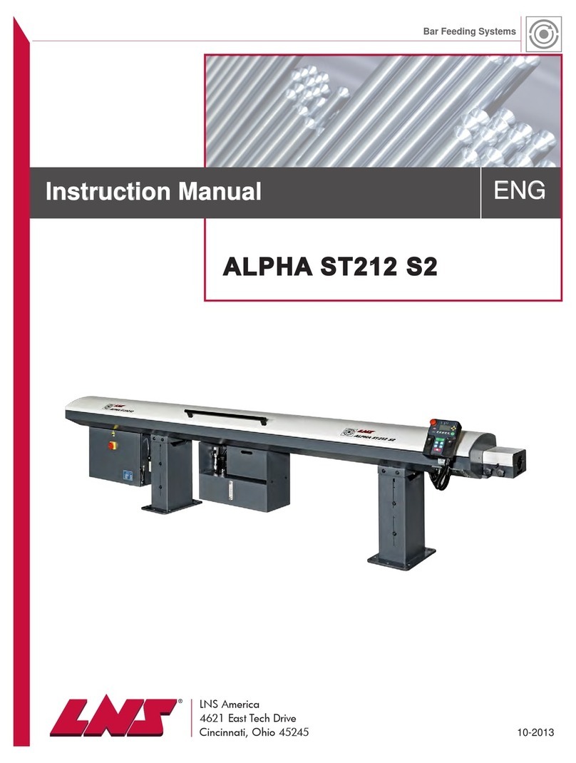
LNS QUICK LOAD SERVO S3 T BARFEED User manual

For CNC machine tool peripherals,
it’s
LNS
, then all the rest
QUICK LOAD SERVO S3 T BARFEED
Service Manual
9.021.04.02.EN. US

GENERAL
SERVICE MANUAL – QL Servo S3-T

GENERAL
SERVICE MANUAL – QL Servo S3-T
IMPORTANT
READ THIS MANUAL CAREFULLY BEFORE USING
AND RETAIN FOR FUTURE REFERENCE.
Published: 08/2020
© LNS America 2020 – 9.021.04.01 EN (V00.0) – Service manual – Printed in LNS America

GENERAL
SERVICE MANUAL – QL Servo S3-T
TABLE OF CONTENTS
1. GENERAL .................................................................................................................................6
ABOUT THIS SERVICE MANUAL ............................................................................................6
WHO IS THIS MANUAL FOR?..................................................................................................6
OTHER APPLICABLE DOCUMENTS .......................................................................................6
IN THE CASE OF DAMAGE CAUSED DURING TRANSPORTATION....................................6
SYMBOLS AND WARNING LABELS........................................................................................7
CONVENTIONAL TERMS AND SYMBOLS..............................................................................8
COPYRIGHT..............................................................................................................................8
LIABILITY...................................................................................................................................8
SAFETY INSTRUCTIONS.........................................................................................................9
2. PROCEDURES........................................................................................................................10
SETUP, ALIGNMENT, AND ANCHOR PROCEDURE ...........................................................10
PUSHER CHANGEOVER .......................................................................................................15
SERVO MOTOR BELT TENSION ADJUSTMENT .................................................................17
CARRIAGE UNIT BELT TENSION ADJUSTMENT ................................................................18
DIAMETER ADJUSTMENT MOTOR REPLACEMENT ..........................................................19
HOME POSITION PROXIMITY SWITCH ADJUSTMENT – SQ5 ...........................................22
MEASURING CELL ADJUSTMENT – SQ3 ............................................................................23
PUSHER REVERSING DISTANCE ADJUSTMENT ...............................................................25
MAGAZINE AND LOADING FINGER ADJUSTMENT ............................................................26
CALIBRATION OF THE LOADING TABLE .............................................................................27
FINDING SOFTWARE/PLC VERSIONS.................................................................................28
SOFTWARE UPDATE .............................................................................................................28
PLC BATTERY REPLACEMENT ............................................................................................29
3. MECHANICAL EQUIPMENT ..................................................................................................30
BAR MAGAZINE......................................................................................................................30
LOADING TABLE ....................................................................................................................34
PUSHER CARRIER.................................................................................................................35
LOADING PUSHER.................................................................................................................36
FEEDING PUSHER .................................................................................................................36
RETRACTION..........................................................................................................................39
KIT FOR SQUARE BARS (OPTION) ......................................................................................39
KIT FOR QUICK PART LOADING (OPTION) .........................................................................40
4. PNEUMATIC EQUIPMENT .....................................................................................................42
LAYOUT OF THE ELEMENTS................................................................................................42
AIR TREATMENT UNIT ..........................................................................................................43
PNEUMATIC BATTERY ..........................................................................................................44
5. ELECTRICAL EQUIPMENT....................................................................................................46
SAFETY COMPONENTS ........................................................................................................46
ELECTRICAL COMPONENTS................................................................................................47
ELECTRICAL CABINET ..........................................................................................................48
REMOTE CONTROL ...............................................................................................................51
SERVO AMPLIFIER ................................................................................................................55
PROGRAMMABLE LOGIC CONTROLLER ............................................................................57
ACCESSORY COMPONENTS ...............................................................................................58
IDENTIFICATION MARKINGS – TYPE OF MATERIAL .........................................................59
CONNECTIONS ......................................................................................................................60
GENERAL
SERVICE MANUAL – QL Servo S3-T
6. SETTINGS .............................................................................................................................. 64
DESCRIPTION........................................................................................................................ 64
ACCESS TO THE FUNCTIONS ............................................................................................. 65
END OF BAR POSITION ........................................................................................................ 81
TOP-CUT POSITION .............................................................................................................. 83
7. MAINTENANCE...................................................................................................................... 86
INSPECTIONS ........................................................................................................................ 86
UPDATING THE PROGRAM ON A PLC................................................................................ 87
CLEANING .............................................................................................................................. 92
8. TECHNICAL CHARACTERISTICS ........................................................................................ 94
9. DISPOSAL .............................................................................................................................. 96
MACHINE................................................................................................................................ 96
10. TROUBLESHOOTING............................................................................................................ 98
ALARMS.................................................................................................................................. 98
SEQUENCE DIAGRAM ........................................................................................................ 102
SEQUENCE LISTING ........................................................................................................... 103
MITSUBISHI ALARM LIST MRJ-4 ........................................................................................ 105
MITSUBISHI WARNING LIST MRJ-4 ................................................................................... 109
MITSUBISHI ALARMS CAUSE AND SOLUTIONS.............................................................. 110
PLC INPUTS/OUTPUTS ....................................................................................................... 116
PRODUCT MANUALS .......................................................................................................... 117
AFTER-SALES SERVICE..................................................................................................... 119
11. APPENDICES ....................................................................................................................... 120
GLOSSARY........................................................................................................................... 120
WIRING DIAGRAM 021-40-620F CE MRJ-4....................................................................... 121
WIRING DIAGRAM 021-40-650F CE DCS MRJ4 ............................................................... 131
WIRING DIAGRAM 021-40-622C CE MRJ4 QLSIII MI ....................................................... 142
PNEUMATIC DIAGRAM ....................................................................................................... 150
ORDER FORM...................................................................................................................... 151

GENERAL
SERVICE MANUAL – QL Servo S3-T

GENERAL
SERVICE MANUAL – QL Servo S3-T
1. GENERAL
ABOUT THIS SERVICE MANUAL
This service manual describes the maintenance and setting procedures for the bar feeder.
For more information on best practices for installation and use, refer to the instruction manual.
WHO IS THIS MANUAL FOR?
Service technicians:
•Qualified technicians who are authorized to:
- assemble and install the machine
- perform repair and maintenance work
- operate on electrical equipment
- modify certain components of the machine
Manufacturer:
•Qualified technicians who are authorized to:
- assemble and install the machine
- perform repair and maintenance work
- operate on electrical equipment
•Engineers/experts who are authorized to:
- modify the machine software
- modify certain components of the machine
OTHER APPLICABLE DOCUMENTS
The machine contains integrated components from other manufacturers.
In the case of these components, their respective manufacturers have carried out a risk assessment, and have declared that
their design is fully compliant with the European standards in force.
Information regarding the proper use of these integrated components is available in the component instructions and provided
by the various manufacturers.
The feeder complies with the European standards that are specified in the declaration of conformity and integration.
IN THE CASE OF DAMAGE CAUSED DURING TRANSPORTATION
LNS accepts no responsibility in case of deterioration or degradation of the products during their transportation.
LNS will assert a claim for loss or damage to those carriers that have been arranged by LNS. If LNS does not make the
freight arrangements, we are not responsible for the freight issues once the article has been loaded on the truck from our
dock.
If you notice that the product is damaged at the time of delivery. Please take pictures, and contact LNS.

GENERAL
SERVICE MANUAL – QL Servo S3-T
SYMBOLS AND WARNING LABELS
Warning labels and consequences in case of non-compliance with the safety instructions
DANGER
Type and origin of danger!
Consequences of non-compliance with the warning.
What to do to avoid danger.
Warnings of imminent danger, which, if not avoided, may result in:
serious or fatal injury
WARNING
Type and origin of danger!
Consequences of non-compliance with the warning.
What to do to avoid danger.
Warnings of potential danger, which, if not avoided, may result in:
serious or fatal injury
CAUTION
Type and origin of danger!
Consequences of non-compliance with the warning.
What to do to avoid danger.
Warnings of a potentially dangerous situation, which, if not avoided, may cause:
minor injuries.
NOTICE
Type and origin of danger!
Consequences of non-compliance with the warning.
What to do to avoid danger.
Warnings of a potentially dangerous situation, which, if not avoided, may cause:
Material damage.
INFORMATION
Type and origin of danger!
Consequences of non-compliance with the warning.
What to do to avoid danger.
Information and notes
CAUTION
Type and origin of danger!
Consequences of non-compliance with the warning.
What to do to avoid danger.

GENERAL
SERVICE MANUAL – QL Servo S3-T
Warnings of a danger, which, if not avoided, may lead to:
damage to the environment
CONVENTIONAL TERMS AND SYMBOLS
The instructions for use of the following conventional terms and symbols:
General risks
Risks of electrocution
Crushing hazard
Harmful to the environment
Material damage
Information, notes
→
Return
1), 2)
Instructions for individual actions consisting of several steps
The diagrams of the plates illustrated in this manual make no distinction between the different models.
Therefore, they apply to all models covered by this service manual.
The service manual uses the following designations to define the position of an element in space (positioning).
The terms "left", "right", "front" and "rear" refer to the direction of use of the machine.
COPYRIGHT
Any reproduction, recording or distribution of all or part of this manual, in any form or by any means, mechanical, photographic,
audio or other, is strictly prohibited without the express written permission of LNS.
LNS accepts no liability for any errors in this manual and any resulting complications.
The product names indicated in this manual are registered trademarks.
LIABILITY
LNS and its subsidiaries accept no liability for any debts, losses, expenses or damages incurred or suffered by the purchaser
of this product or a third party as a result of an accident, misuse or improper use, or effects arising from unauthorized
modification, repair or alteration by LNS.
LNS and its subsidiaries will not be liable for damages and problems arising from the use of options and products other than
those provided or approved by LNS.

GENERAL
SERVICE MANUAL – QL Servo S3-T
SAFETY INSTRUCTIONS
NOTICE
The manufacturer accepts no responsibility for damage resulting from non-
compliance with the documentation.
•LNS accepts no responsibility for accidents or material damage resulting from failure to observe the safety instructions.
•Never handle the equipment without taking into account the safety instructions and instructions for use. Safety
instructions for the bar feeder, as well as the CNC lathe, must be strictly observed.
•The equipment must not be used or handled by unskilled personnel, children or persons under the influence of alcohol or
medication.
•It is recommended not to wear jewelry and loose clothing, and to tie long hair.
•Always uncouple the bar feeder from the machine before removing the covers.
•It is strictly forbidden to remove safety equipment. If necessary, to ensure the smooth running of an adjustment or
maintenance procedure, it must be reinstalled immediately afterwards.
•Never walk on the belt.
•Never put your hands into the moving bar feeder.
•No servicing should be carried out on the interface or inside the electrical cabinet while the bar feeder or the lathe is
powered on.
•It is strictly forbidden to bridge or remove circuit breakers and main switches, especially safety switches.
•To ensure the safety of components and personnel, observe the points indicated for lifting and moving the bar feeder. It
is expressly forbidden to stay near the suspended load or in the operating area of the crane, the forklift truck or any other
lifting and transport equipment.
•Be careful not to hit the bar feeder when it is moving, as this may damage it.
•Never move the bar feeder while it is powered on.
•Always switch off the bar feeder prior to service, maintenance or repair.
•The work area around the bar feeder must be well lit and clear. It is important to clean the floor on a regular basis, as the
presence of oil can result in falls.
•Do not place the machine in a damp area, and make sure that the water or oil never comes into contact with the
electrical equipment.
•Never try to recharge the batteries of the PLC.
•Always use the parts supplied or recommended by LNS for use/intervention on the bar feeder for maintenance purposes.
•If it is necessary to move the bar feeder after commissioning, always contact LNS or a local representative before
restarting the system.

PROCEDURES
SERVICE MANUAL – QL Servo S3-T
2. PROCEDURES
SETUP, ALIGNMENT, AND ANCHOR PROCEDURE
INFORMATION
The following conditions must be met to complete this procedure:
•Bar feeder power off
•No pneumatic pressure
Reminders:
•To obtain a perfect alignment, it is advisable to install the largest feeding pusher.
•If a spindle liner is installed, make sure that its I.D. is larger than the O.D. of the feeding pusher.
•It is not mandatory that the lateral level of the bar feed system is perfect; just make sure that the latter is as straight as
possible.
•The longitudinal level of the bar feed system must be adjusted according to the level of the lathe, even if the lathe lies
only over three points and cannot be perfectly levelled.
Should the level of the bar feed system not correspond to that of the lathe, the feeding pusher might touch the inside
of the spindle.
Place the bar feeder as close as possible behind the headstock lathe. The distance between the front of bar feeder and the
back of headstock lathe should be as small as possible.
Before proceeding with the alignment of the bar feed system, ensure that the lathe is stable and levelled.
1. Position the bar feed as close as possible to the rear of the lathe. The distance between the front
of the bar feed and the back of the spindle should be as small as possible.
Note :
If obstacles prevent the bar feed from being positioned within 8 inches of the back of the spindle an
extension will be required.

PROCEDURES
SERVICE MANUAL – QL Servo S3-T
2. Level the bar feed in the x and y axis using a torpedo level. The level can be placed on the linear
belt rail to verify the y-axis and on the retract rails to verify the x-axis. Use the leveling screws
(shown with arrows) on the retract to adjust unit to level.
3. Carefully loosen the 16 screws located in the slots on the base of the unit. This will allow the unit
to be adjusted up and down.

PROCEDURES
SERVICE MANUAL – QL Servo S3-T
4. Using the central jackscrew (1) and the hexagonal tube (2) supplied with the bar feed; adjust the
unit so that the pusher is centered up and down at the back of the spindle. Make sure that the unit
raises or lowers uniformly.
5. Once the pusher is centered up and down, tighten the 16 screws to secure unit and recheck the
level of the unit.
1
2

PROCEDURES
SERVICE MANUAL – QL Servo S3-T
6. Align the unit side to side by centering the pusher in the back of the spindle and then extending the
pusher to the back of the collet and centering it there.
Adjust the rear of the bar feed when centering to the rear of the spindle and the front of the bar feed
when centering to the rear of the collet.
Once the pusher is centered at the back of the collet recheck the alignment at the back of the spindle
by pulling the pusher back.
Continue until the pusher is centered at the rear of the spindle and the rear of the collet..
7. Once the bar feed has been aligned anchor it using the ½ inch anchor bolts supplied with the unit.

PROCEDURES
SERVICE MANUAL – QL Servo S3-T
8. After anchoring the unit, recheck the level and the alignment of the unit.
9. After the alignment has been rechecked, power and air will need to be hooked up to the bar
feeder.
10. Once the power and air have been hooked up, the bar feed must be calibrated.
After calibrating the bar feed, return to this procedure and move on to Step 11 for the final
alignment.
11. For final alignment, load a bar into the v-channel and verify that it can be loaded into the spindle of
the lathe without hitting the sides of the spindle or spindle liner.
If the bar hits side to side the alignment will have to be adjusted.

PROCEDURES
SERVICE MANUAL – QL Servo S3-T
PUSHER CHANGEOVER
INFORMATION
The following conditions must be met to complete this procedure:
•Bar feeder switch on
•Loading table in lower position
•Pusher at the mechanical home position
•Bar feed in STOP mode
1. Open the main access cover.
2. Measure the distance of the End-of-Bar
bushing.
3. Pull the carrier away from the home position.
4. Loosen up the setscrews to release the
pusher.

PROCEDURES
SERVICE MANUAL – QL Servo S3-T
5. Pull out the guide bushing from the front ring.
6. Remove the pusher from the bar feed.
7. Put the new pusher in the bar feed.
8. Push the guide bushing in the front ring.
9. Place the rear end of the pusher in the carrier
and tighten the setscrews.
10. Adjust the End-of-Bar bushing to the distance
measured at setp 2.
11. Close the main access cover.

PROCEDURES
SERVICE MANUAL – QL Servo S3-T
SERVO MOTOR BELT TENSION ADJUSTMENT
INFORMATION
The following condition must be met to complete this procedure:
•Bar feeder POWER OFF
1. Open the main access cover.
2. Loosen the four nuts on the motor mount plate.
3. Using a lever (ex. screwdriver),
raise the motor to create tension
on the belt.
4. Holding the belt taut, tighten the four nuts on the motor mount plate.
5. Once the tension is adjusted, remove the lever and close the main access cover.

PROCEDURES
SERVICE MANUAL – QL Servo S3-T
CARRIAGE UNIT BELT TENSION ADJUSTMENT
INFORMATION
The following conditions must be met to complete this procedure:
•Bar feeder POWER on
•Bar feed in [STOP] mode
1. Open the main access cover.
2. Loosen the four nuts on the motor mount plate.
3. On each end of the carriage unit are black plastic end caps. In the center of the end cap on either
side, right above the belt is an opening with a 3mm Allen head tensioning screw inside.
Turn the screw CW to add tension to the belt and CCW to release tension.
4. Once the tension is adjusted, remove the lever and close the main access cover.

PROCEDURES
SERVICE MANUAL – QL Servo S3-T
DIAMETER ADJUSTMENT MOTOR REPLACEMENT
INFORMATION
The following conditions must be met to complete this procedure:
•Bar feeder POWER on
•Bar feed in [STOP] mode
1. Remove the front panel on the sub-base.
2. Remove the two rear panels on the sub-base.
3. Remove the four screws holding on the chain guard cover plate.
Table of contents
Other LNS Industrial Equipment manuals

LNS
LNS QL Servo 80 S2 User manual

LNS
LNS TRYTON 107 User manual

LNS
LNS Hydrobar Express 220 Guide

LNS
LNS QUICK SIX Programming manual

LNS
LNS GT 326-E User manual

LNS
LNS Express 332 S2 User manual

LNS
LNS HYDROBAR SPRINT S3 User manual

LNS
LNS SERVO S3 T User manual

LNS
LNS GT 112-E User manual

LNS
LNS QUICK LOAD SERVO III MI User manual

LNS
LNS FOX SC2 330 User manual

LNS
LNS Hydrobar Express 332 Guide

LNS
LNS Blaze Air User manual

LNS
LNS Alpha 552 User manual

LNS
LNS Hydrobar Express 220 Installation and operation manual

LNS
LNS HYDROBAR SPRINT 555 User manual

LNS
LNS ALPHA SL65 S User manual

LNS
LNS TRYTON 112 User manual

LNS
LNS ALPHA ST212 S2 User manual

LNS
LNS Express 220 S2 User manual