AP&T AP-AB1205 User manual

AP&T
R
Shanghai Anping Static Technology Co.,Ltd
High Ecient Electroshock-proof
AP-AB1205 Ion Bar
AP&T

Widely used in printing, UV atbed industry
Eectively solve the problem caused by static electricity
Prevent sticking Prevent uneven scattering
Prevent adhesion of objectsStatic removal Control ink splashing

High ecient
Safe
Static removal

Positive high voltage amplitude
正高压幅值
Negative high voltage amplitude
time
The negative ion output increases with the
increase of negative high voltage amplitude
The negative ion output increases with the
decrease of negative high voltage amplitude
Adjust ion balance voltage
Vp
Vp Vp
Vp
Vn
Vn Vn
Vn
Adjust the output frequency of
positive and negative high voltage
The output frequency of positive and
negative ions increases
The output frequency of positive
and negative ions decreases
time
-HV
(Negative high voltage)
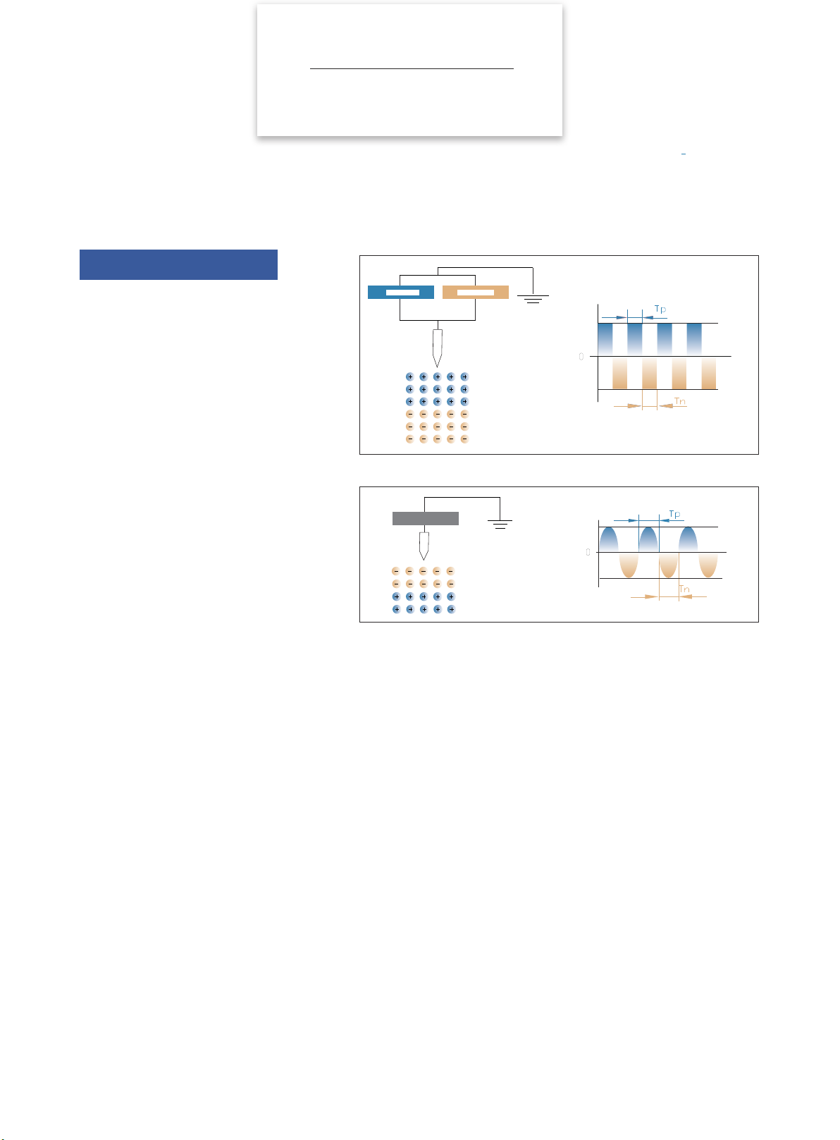
The output ratio of positive and negative ions is adjustable, which can be used to
adjust the ion balance voltage
The output frequency of positive and negative ions is adjustable, which can be
applied to different discharge distance to achieve faster discharge speed
Ion balance/
ion output frequency adjustable
Intelligent Control
+HV
(Positive high voltage)
Positive voltage working time
Negative voltage working time
-HV
(Negative high voltage)
+HV
(Positive high voltage)
Positive voltage working time
Negative voltage working time
time
-HV
(Negative high voltage)
+HV
(Positive high voltage)
-HV
(Negative high voltage)
+HV
(Positive high voltage)
Positive voltage working time
Negative voltage working time
Positive voltage working time
Negative voltage working time
-HV
(Negative high voltage)
+HV
(Positive high voltage)
-HV
(Negative high voltage)
+HV
(Positive high voltage)
+HV
(Positive high voltage)
+HV
(Positive high voltage)
-HV
(Negative high voltage)
-HV
(Negative high voltage)
Positive high voltage amplitude
Negative high voltage amplitude
Adjust ion balance voltage
time
time time
Adjust the output frequency of
positive and negative high voltage
time time

Intelligent Control
Ion balance/
ion output frequency adjustable
Button function instructions
Function Symbol Operation instructions
Unlock Unlock before adjusting operating parameters.
Run / Pause Device starts running when power is on. Press "STOP" to standby and no high voltage
output. Press "RUN" again and the device will start working.
Adjust
cleaning cycle CTTH → +/-
Press CTTH first, then +/- to increase or decrease the cleaning cycle. The default cleaning
period is 15 days, and the adjustment range is 1-60 days. The cleaning function will alarm when
the countdown is 0 days. Power off and restart to restore the set time. The cleaning function
becomes invalid if the value is set to 0 days.
Adjust
frequency FREQ → +/- Press FREQ first,then press +/- to increase or decrease the frequency of positive and negative
ions output .
Adjust
ion balance voltage IBN → +/- Press IBN first, then press + when the positive voltage on flat panel detector or discharge object
surface is high, press IBN first, then press - when the negative voltage on flat panel detector or
discharge object surface is high until the ion balance reaches the ideal status.
Confirm CAL → OK Press CAL and then OK to confirm after the output parameters are adjusted.

Pulse AC
The eect of static eliminating is better
compare to power frequency AC ion bar
Pulse AC
Traditional AC
Pulse AC
Positive pulse Negative pulse
T
Pulse AC Positive voltage working time
Negative voltage working time
+HV
(Positive high pressure)
-HV
(Negative high pressure)
AC
power supplyHigh voltage
Frequency AC
T
Positive voltage working time
Negative voltage working time
+HV
(Positive high pressure)
-HV
(Negative high pressure)
Comparison with traditional AC
The pulsed AC method alternately applies "+" and "-"
high voltage to one electrode needle to generate two
polar ions.
Compared with the AC method, the ion generation
efficiency is higher.Electrostatic elmiination ability
can be fully plated on matter for short or long
distance.Beside,frequency adjustable so the working
distanceis extended.Positive and negative ion output
ratio adjustable so easy for intelligent control.

30mm
150mm
0s
0s
0.1s
1.0s
1.7s
3.2s
3.1s
5.1s
2.8s
3.1s
2.3s
6.0s
150mm
50mm
70mm
100mm
Ion bar length: 410mm; working frequency: 30Hz;
Test distance (mm) Discharge speed
Positive discharge time
(S)
Negative discharge time
(S)
Ion Balance voltage
(V)
Vertical Level
30
-150 1.0 1.7 -13.5
0 0.0 0.0 -6.3
150 2.8 2.7 10.1
50
-150 1.4 3.2 -23.3
0 0.0 0.0 7.5
150 1.8 3.1 -15.8
70
-150 3.0 3.1 17
0 0.1 0.1 13.7
150 2.1 2.3 19.9
100
-150 5.1 4.2 2.75
0 0.5 1.0 9.9
150 6.0 5.4 21.3
Test Conditions:
Test standard: ANSI/ESD.STM3.1, SJ/T 11446—2013
Test instrument: Trek157 static tester
Test voltage: ±1000V → ±100V attenuation
Test environment: humidity 50±5%; temperature 23±3℃
Ion bar length:410mm
Working frequency:30Hz
150mm*150mm Flat tester
The test data diagram is as follows (test distance: 100mm, ion bar length: 410mm, working frequency: 30Hz):
Test data under other conditionsare as follows
Test diagram
Eciently static removal
Stay away static trouble &
for clean production environment

No.1
No.5
No.3
No.4
No.2
Easy installation
M5 sheet slider nut installation accessories provided.
Put the slider nut into the slot of the ion bar. Slide left
and righ to adjust position and can adapt to various
installation environments.
Electroshock-proof
Protection against electroshock.
DC24V high exible towline power cord
The standard length of the power cord is 1500mm and the low-
voltage wiring of 24V can eliminate the aging phenomenon
of the cable caused by the discharge and the impact on the
peripheral equipment,which can build a highly reliable system.
Working status visualization
Red light alarm when high voltage abnormal.
CE certication
It can effectively prevent the external electromagnetic
interference from aecting the normal operation of the ion
bar. This is a static electricity eliminator with high safety
and high reliability.
Features
Safe / Easy to use / Durable

unit:mm
63,5
35
57.5
L
L=200-300mm(Needle spacing 25mm);350-3000mm(Needle spacing 50mm)
DC24V high exible towline power cord
M5-12*12*4 square nuts
Working status indicator Needle holder and electrode needle
Strip grounding electrode
Front
Back
M5-12*12*4 square nuts
DC24V high flexible towline power cord
Working status indicator
Needle holder and electrode needle Strip grounding electrode
Product Size
Product Details
Specication
Details / Parameter / Size

Model AP-AB1205
Input voltage DC 24V
Power 10W
Electrode pin voltage Vpp:8-12KV
Ion emission Pulse AC
Emitter electrode SUS
Discharge structure Resistance coupling
Output frequency 1,3,5,10,20,30,50Hz; (EX-Work setting: 30Hz)
Discharge range L*W*H:Bar Length*200*100mm
Installation distance 30→100mm
Ion balance ≤|±30V|(AV E )
Discharge speed ≤1S (Test distance 100mm)
Status indicator Green light - normal,Blue light - standby,Blue light flashing—debugging /cleaning,Red light - Abnormal high voltage
Working temperature 0℃-50℃
Working humidity <70%
Dimensions(L*W*H) {200-300mm( Needle spacing 25mm);350-3000mm( Needle spacing 50mm)}*35mm*63.5mm
Bar material Flame retardant PVC, AL, SUS
Packaging accessories M5-12*12*4 square nut
Warranty 1 year
Certication CE
Product Parameter

1 2
34
+-
OK
CTTH
PWM FREQ CFM
IBV
IBN
123
6
5
4
IBP
CAL ALTH
AP&T
R
DC24V high flexible towline power cord wiring diagram
1.Take out the ion bar, adapter power supply, power supply network cable ,
stainless steel mounting brackets and other accessories from the packing
box.
2.Install the stainless steel mounting brackets on the base mounting slot on
the ion bar.
Connection method 1: Connect one end of the DC24V high-exible power
supply cable to the industrial control power supply and insert one end of the
aviation plug into the aviation socket on the ion bar.
Connection method 2: Connect one end of the network cable into the DC24V
adapter power supply and the other end into the aviation socket on the ion bar.
Use the remote control to adjust the voltage output parameters under the
appropriate air pressure.When the positive voltage on the surface of the
at panel detector or the object to be discharged is large, press to adjust
"IB-"; when the negative voltage on the at panel detector or the surface
of the object to be discharged is large, press "IB+" to adjust until the
balance is adjusted to the ideal status.
The panel indicator lights green to show that the ion bar is working.
Power cord colorPo Connecting info
Orange +24V
White 0V
Green EGND
Use of the product
Installation step / Installation position /
Packaging accessories
Adjustable bracket
Bracket installation
Connection method 1
Connection method 2
Green light
Installation step

Working frequency
(Hz)
nstallation distance
(mm)
55 100
30 100
10 150
5 200
1 250
1. Choose the best static elimination position and install the bar body and the matching power adapter rmly after the static detection of the on-site
working environment. The installation angle should be perpendicular to the surface of the charged body and the installation distance can be referred
to the following table. (Ex-work setting is 30Hz. Use the remote control to adjust if you need to adjust the output frequency. Congure a at panel
tester if you want to see the adjustment results)
2. The ion bar grounding electrode is not allowed to be covered by other objects.
3.3. It is advisable to install two ion bars side by side with an interval of more than 100mm
Two ion bars should be staggered by more than 100mm if they are to be installed face to face.
4. It is advisable to be more than 200mm away from obstacles such as walls.
5. For the safe use of the ion bar, the ion bar discharge electrode should be at least 30mm away from the metal conductor and metal
grounding body and the bar body must be reliably connected to the grounding wire.
≥ 100mm
≥ 100mm
Installation position
Charged object
WALL
WALL
WALL
WALL
Metal conductor
Metal conductor
Metal conductor
Metal conductor

Name Image Part No. Specication Quantity
Power Adapter OSP000601
GRT-240200: DC24V 2A, dual network port
output,
Size: 123*61*40.5mm (L*W*H)
1
National standard power
cord 8YXG25110 Standard:1.8m, optional:3m/5m 1
Three-core exible power
cord with aviation plug
(optional)
—— Standard 1.5m (customizable on site) 1
Network cable (optional) —— Standard:2.5m, 5m/10m:optional 1
L-shaped stainless steel
mounting bracket AP8038005 Height 25mm/Width 16mm/ Thickness 3mm
Aperture 5mm (measured 4.8mm) 4
Square nut AP8933000 M5*12*12*4 2
304 stainless steel spring
washer AP8943000 M5 6
304 stainless steel at
gasket AP8946004 M5 6
304 stainless steel pan
head Phillips screw AP8900001 M5*12 6
Hex nuts 1LML05000 M5 4
Needle holder AP6604000 —— ——
Remote control AP2253011 Infrared remote control, neutral panel
(L*W*H: 85.76*39.76*6.66) 1
Packaging accessories
+OK -
CTTH
PWM FREQ CFM
IBV
IBN
123
6
5
4
IBP
CAL ALTH
AP&T
R
1. Please read the instruction manual carefully before installing and using this equipment.
2. The whole set of equipment must be reliably grounded during use, otherwise it is easy to cause abnormality or even damage to the ion bar.
3. Do not use this equipment in environment where humidity is > 70%.
4. It is strictly forbidden to use this equipment in flammable and explosive environments.
5. Unauthorized disassembly of the product is strictly prohibited, internal maintenance and repair must be performed by professionals.
6. The product is strictly prohibited to touch liquid during use, otherwise an abnormality may occur and cause electric shock or fire.
7. Power must be turned off during inspecting or replacing the product, otherwise it may cause electric shock or fire.
8. The product is specially designed to eliminate static electricity. It is strictly forbidden to use it for other purposes. Any abnormal use may
cause machine failure, electric shock, fire and other accidents.
9. Its strictly forbidden to touch the electrode needles when power is on, otherwise it is easy to cause malfunctions and electric shock
accidents.
10.The electrode needle is a sharp metal object, please use it with care.
11.Please check the specifications of the power supply before powering on the product. Any power supply that does not meet the
specifications will cause damage to the product.
12.Please check the product power cord/communication cord regularly and replace it immediately if it is damaged. Otherwise it is easy to
cause problems such as electric leakage, poor communication, and abnormal operation.
Safety warning

NO.
1The indicator on the
panel is off
Confirm the power supply specification(INPUT:100—240VAC
50/60Hz;OUTPUT:24VDC 2000mA)
Whether the discharge seat is tightened Confirm the discharge seat is tightened
2
Panel indicator red light on Confirm the installation location and stay away from surrounding
conductors
3
4
Return to factory for maintenance
High voltage module is damaged or insulation
of the discharge seat is damaged Return to factory for maintenance
Trouble shooting
Faults Reasons Solutions
The electrostatic removal
performance decreased
obviously
The electrostatic removal
performance decreased
Unable to discharge
The product is smoky or burnt
Poor contact of the power cable
Power supply mismatch
Discharge needle is polluted and damaged
Ion bar positioning is incorrect
There are conductors or other ion bar around
Electromagnetic interference
Abnormal discharge
No power supply for high voltage module
High voltage module is damaged
Main-board chip is damaged
Check whether the power cable is in good condition and
securely connected
Clean or replace the discharge needle
Confirm the best installation location
Remove (moving) conductors or other ion bar
Turn off the power switch / unplug the power cable, restart
the ion bar
Check the grounding of the ion bar and plant equipment, and return
to the factory for maintenance
Main-board chip is damaged caused by
poor grounding or no grounding
5
6
AP-AB1205 has undergone rigorous testing and aging treatment before ex-work. Its performance has completely reached the
relevant indicators marked in the usage instruction.
1. AP&T makes a commitment to the customer that any defective parts inspected by AP&T will be repaired or replaced free of charge
within one year from the date of purchase. However, this commitment does not apply to:
(1) The device is incorrectly used or installed.
(2) Damage caused by negligence or accident during use.
(3) Modified, disassembled or repaired by other service departments not authorized by Anping Company.
2. The alloy electrode is a consumable product which is not included in the scope of warranty and will be charged for replacement when
repairing.
3. AP&T shall not be liable for any incorrect use of the products except for repair or replacement of parts as specified above.
After-sales service1. The ion bar should be cleaned and maintained in time according to the use environment and the required electrostatic protection
requirements in order to ensure the good performance of the product. That is, gently remove the carbon deposits on the discharge
electrode, discharge socket, and metal discharge body with electrostatic brush, dust-free cotton swab, dust-free cloth dipped in
anhydrous alcohol, which will improve its performance significantly. Note:
A. Operation must be done 10 minutes after power cut off.
B. It must be cleaned when dust or white products appear on the tip of the needle during use. Use dust-free cloth dipped in anhydrous
alcohol to clean when brush can not meet the cleaning requirements.
C. The ion bar must be powered on after alcohol is completely volatilized after cleaning. No other organic solvent can be used to clean
the ion bar.
2. If the switch working indicator light of the power plug-in port on the panel of the ion bar is off , it should be stopped and repaired by
professional maintenance personnel. It can be used only after the electrical performance index is normal.
Maintenance

Speciality Creates ValueSpeciality Creates Value
Shanghai Anping Static Technology Co.,Ltd
Tel : 021-64517676
Fax : 021-64517673
Postcode : 200233
Website : www.ap-static.com
Address : 3/F,Building 27,No.69,Guiqing Road,Shanghai,China
Table of contents
Other AP&T Industrial Equipment manuals