E1
12.11.2006
Table of Contents
Chapter 1:........................................................................................1-1
Alarms................................................................................................................................1-1
Switches and cells list..................................................................................................................1-2
A01 – Emergency stop line open ................................................................................................1-3
A02 – Main access cover open....................................................................................................1-4
A03 – Magazine protection grid open.........................................................................................1-5
A04 – Bar feeder retracted or not locked in its working position.............................................1-6
A11 – Measuring cell SQ3 signal defective ................................................................................1-7
A12 – Home position proximity switch SQ5 signal missing.....................................................1-8
A15 – Safety time for loading channel up and down motion elapsed......................................1-9
A16 – Safety time for diameter adjustment elapsed................................................................1-10
A21 – Measuring cell SQ3 activated too early..........................................................................1-11
A22 – Signal A2 "lathe in automatic mode" interrupted during loading cycle......................1-12
A23 – Safety time for loading profiled bar elapsed..................................................................1-13
A24 – Safety time for top-cut positioning elapsed ..................................................................1-14
A25 – Lathe did not resume its production cycle....................................................................1-15
A26 – Clamping device closed prior to completing the feed out............................................1-16
A27 – Clamping device opened during production cycle without lathe auto mode.............1-17
A28 – Parts counting parity error by M-code quantity and automatic part counting ...........1-18
A30 – Bar stock loading error....................................................................................................1-19
A41 – Servo amplifier / PLC communication fault...................................................................1-20
A42 – Servo drive alarm @@.....................................................................................................1-21
A43 – Amplifier battery low........................................................................................................1-22
A44 – Servo motor not ready.....................................................................................................1-23
A45 – Servo motor positioning error during sequence @@...................................................1-24
A50 – Servo amplifier firmware not compatible with PLC.......................................................1-25
Bar Feeder Software Sequence of Events................................................................................1-26
Mitsubishi Servo Amplifier Alarm List......................................................................................1-27
Chapter 2:........................................................................................2-1
Common Issues ................................................................................................................2-1
Vibrations......................................................................................................................................2-2
Servo Motor Following Error During Sequence 9......................................................................2-3
Part feed out accuracy.................................................................................................................2-4
Chapter 3:........................................................................................3-1
Procedures ........................................................................................................................3-1
Alignment Procedure ...................................................................................................................3-2
Pusher Changeover Procedure...................................................................................................3-6
Belt Tension Adjustment .............................................................................................................3-9
Home Position Proximity Switch SQ5 Adjustment.................................................................. 3-10
Diameter Adjustment Motor Proximity Switch – SQ4..............................................................3-11
Measuring Cell Adjustment – SQ3 ............................................................................................3-12
Pusher Reversing Distance.......................................................................................................3-14
Reference Procedure..................................................................................................................3-15
Calibration of the Loading Table...............................................................................................3-17
Chapter 4:........................................................................................4-1
Software.............................................................................................................................4-1
Software / PLC Versions..............................................................................................................4-2
Software Update ...........................................................................................................................4-3
Battery Replacement....................................................................................................................4-5
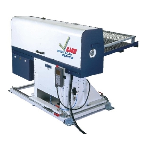
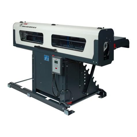
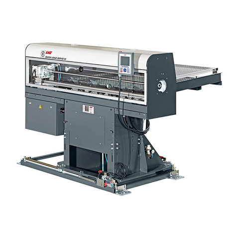
QUICK LOAD SERVO 65/80
