PREPARACIÓN DE LA PUERTA / DOOR PREPARATION: INSTALACIÓN / INSTALLATION:
IMPORTANT: ATTACH LOCK to the door with the mounting screws, using a cross screwdriver. If the
screws are over tightened or loose, the lock may fail. ADJUSTMENT ACCORDING TO THE
FUNCTIONING OF THE LOCK.
IMPORTANTE: FIJE LA CERRADURA a la puerta con los tornillos de montaje, utilizando
un desarmador de cruz. Si los tornillos se aprietan en exceso o quedan flojos la
cerradura puede fallar. AJUSTE SEGÚN EL FUNCIONAMIENTO DE LA CERRADURA.
Tope de retén interior (puntas
en posición vertical).
Inner end stop (tips in vertical position).
Barrenos hexagonales (posición
horizontal).
Hexagonal bores (horizontal position).
Urrea Herramientas Profesionales S.A. de C.V. km 11,5 Carretera A El Castillo, El Salto, Jalisco, México. C.P. 45680, Tel. (33) 3208 7900, RFC
UHP900402Q29, garantiza este producto por el termino de 100 años en sus piezas, componentes y mano de obra contra cualquier defecto de
fabricación a partir de la fecha de entrega.
Condiciones: Para hacer efectiva la garantía deberá presentar el producto junto con la póliza de garantía debidamente firmada y sellada por el
establecimiento donde la adquirió, en cualquiera de los centros de servicio autorizados. Los gastos de transportación que se deriven del
cumplimiento de la garantía serán cubiertos por Urrea Herramientas Profesionales S.A. de C.V. Esta garantía no será valida en los siguientes casos:
· Cuando el producto haya sido utilizado en condiciones distintas a las normales o al desgaste natural de sus partes.
· Cuando el producto no haya sido operado de acuerdo al instructivo de uso que lo acompaña.
· Cuando el producto haya sido alterado o reparado por personas no autorizadas.
Urrea Herramientas Profesionales S.A. de C.V. km 11,5 Carretera A El Castillo, El Salto, Jalisco, México. C.P. 45680,
Tel. (33) 3208 7900, RFC UHP900402Q29, warranties this product for a life time in its parts, components and manual
labor against any manufacture defect from the purchasing date.
Terms: In order to make warranty effective you must present the product along with the warranty properly filled and
signed to an authorized distributor or service center. Urrea Herramientas Profesionales S.A. de C.V. will cover the
transportation cost related to the warranty.
This warranty is not applicable in the following cases:
· When the product has not been used according to normal conditions or natural wear of its parts.
· When the product has not been used according with this user’s manual instructions.
· When the product has been fixed or modified by unauthorized or unqualified person.
PAG. 2-2
A una altura aproximada de 96,5 cm (38") del piso, coloque la plantilla para
marcar la ubicación de la cerradura en las caras laterales y del canto de la
puerta.
- Para la cara lateral, ubique la posición deseada (60 mm o 70 mm) y márquelo.
- En el canto marque el centro del diámetro de acuerdo a la altura aproximada
de 96,5 cm (38") del piso y centrando según el espesor de la puerta.
At an approximate 96.5 cm (38") height from the floor, place the template to mark the
location of the lock on the sides and the edge of the door.
- For the side face, locate the desired position (60 mm or 70 mm) and mark it.
- On the door edge, mark the center of the diameter according to the approximate height
of 96.5 cm (38") from the floor and align to the thickness of the door.
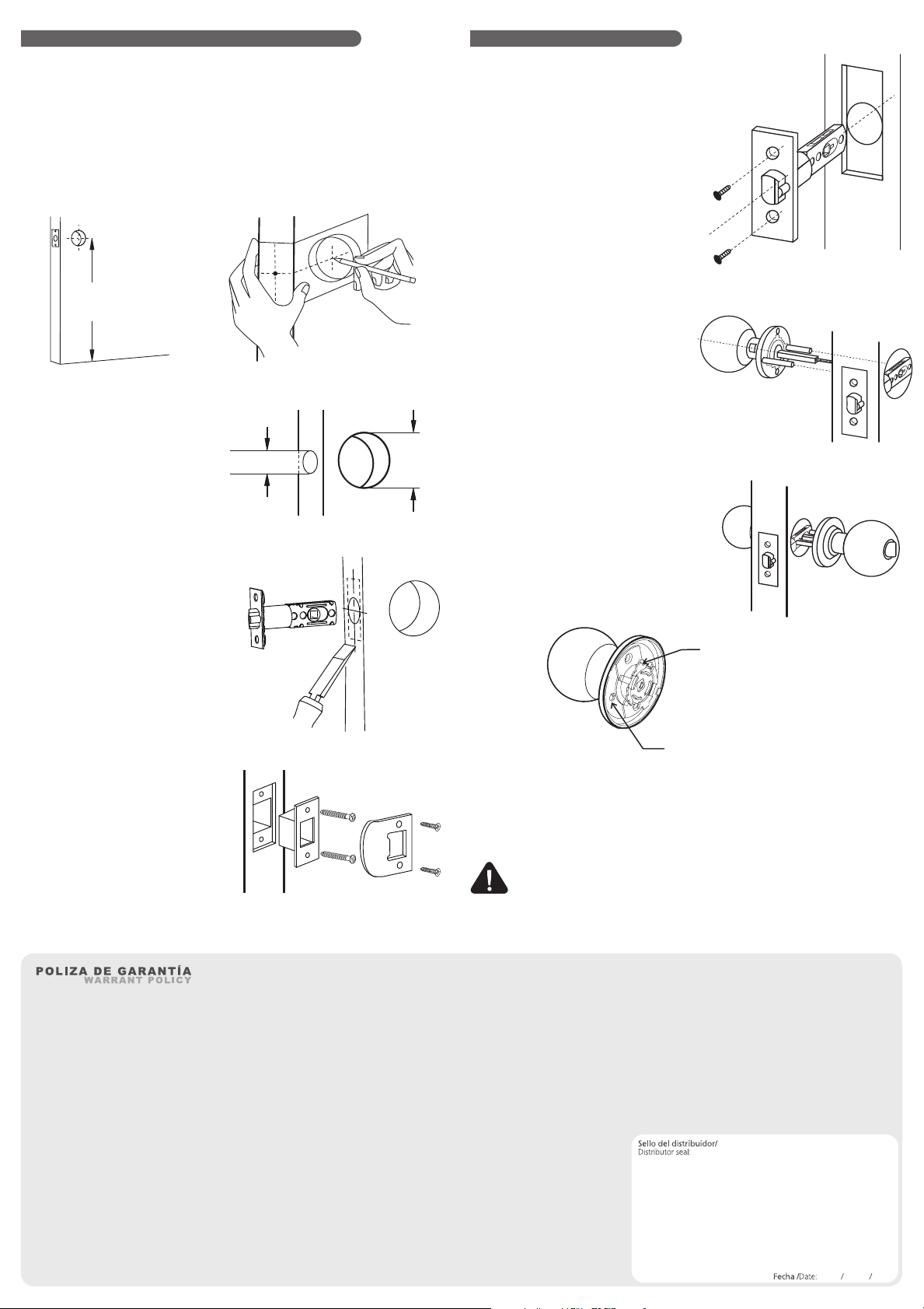
2.
Perfore un circulo de 5,4 cm (2-1/8")
de acuerdo a la distancia elegida en el
picaporte.
Drill a circle of 5.4 cm (2-1/8") according to
the distance chosen on the latch.
3.
Perfore el canto de la puerta 3 mm
(1/8") de acuerdo al frente del
picaporte.
Bored the edge of the door 3 mm (1/8")
according to the faceplate
4.
Perfore el marco de la puerta para la
instalación de la caja-contra y contra.
Ajustar los tornillos.
Drill the door frame for the strike box and
strike installation. Tighten screws.
5.
Coloque el pestillo en la perforación
y fijar con las pijas para madera.
Place the latch on the hole and tighten
wooden screws.
1.
Coloque el pomo exterior alineando
los pernos y el perfil cuadrado con
respecto a la leva del picaporte.
Place the outside knob aligning the bolts and
the square spindle with respect to the cam.
2.
Coloque el pomo interior alineado
con los pernos y el perfil cuadrado del
pomo exterior. Fijar con los tornillos.
Place the interior knob aligned to the outside
knob bolts and the square spindle. Tighten
wooden screws.
3.
38"
965 mm
1"
25,4 mm
2-1/8"
54 mm


