Copyright © 2021, ASSA ABLOY Australia Pty Limited. All rights reserved. Reproduction in whole or
in part without the express written permission of ASSA ABLOY Australia Pty Limited is prohibited.
700002AU Rev 2 06/21
6
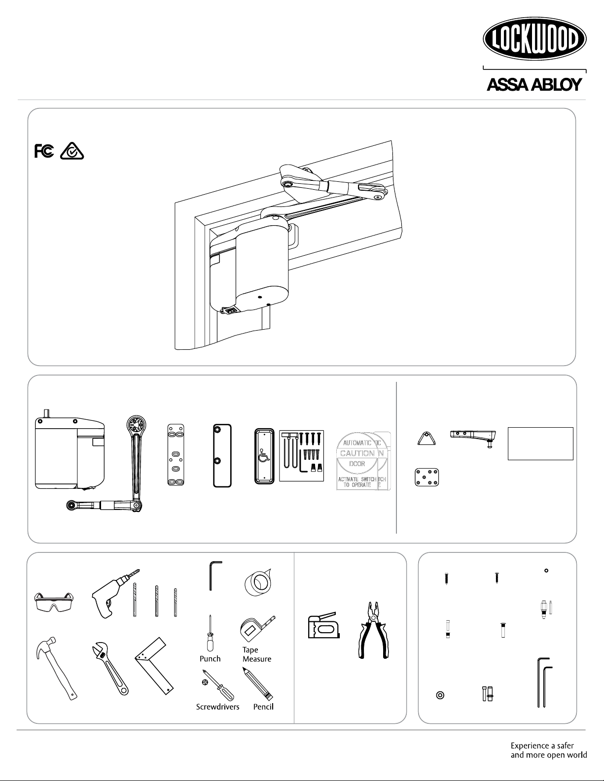
5831 Series Installation and Operating Instructions
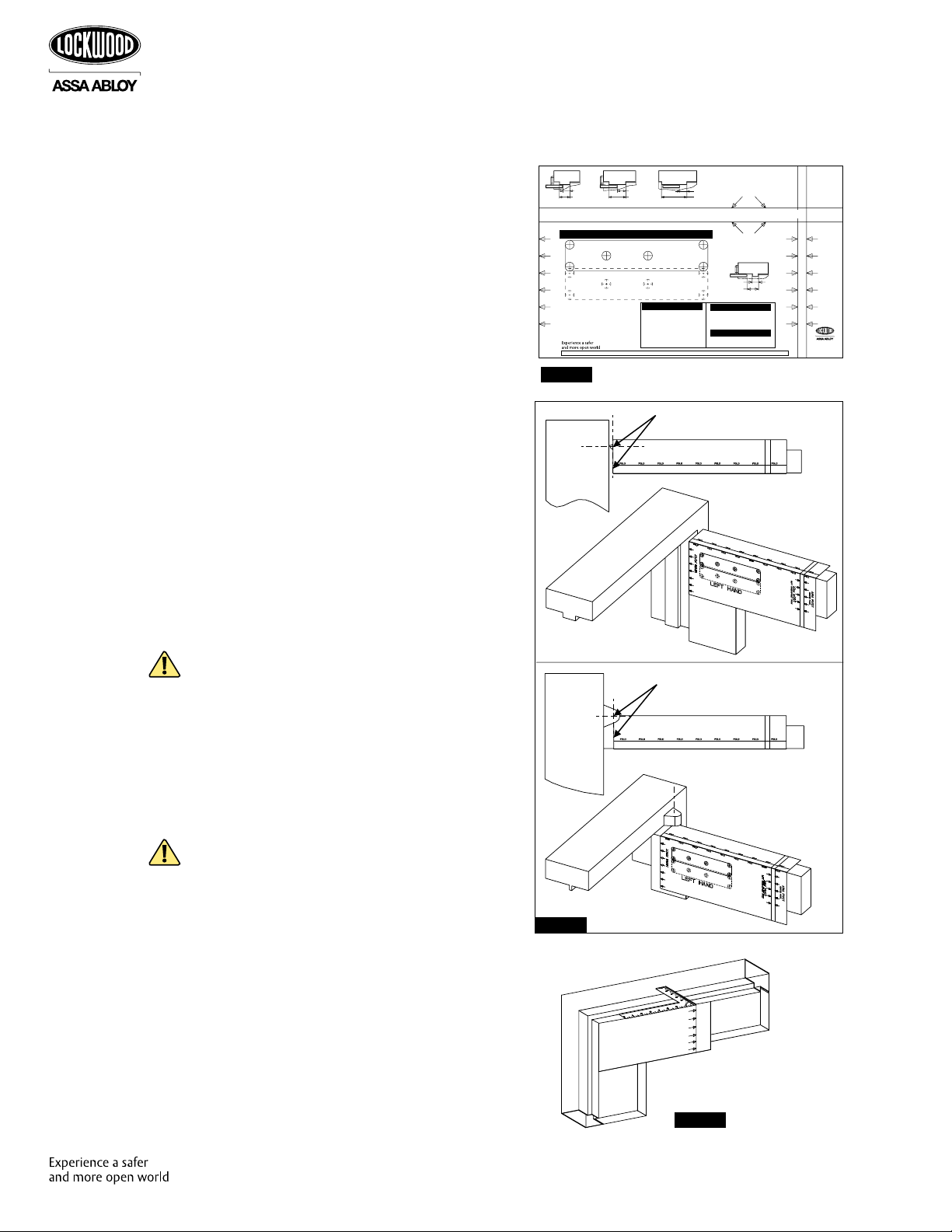
Align Template With Hinge Centerline
Top View
Butt Hinge
Top View
Offset Pivot Align Template With Hinge Centerline
EZ043
1. Select right hand or left hand template and
become familiar with information. (Figure 3)
NOTE: Refer to “Determine Door Handing and
Mounting Type” on page 5 to verify hand. A
push side operator always mounts on push-to-
open side of door at hinge.
2. Measure stop thickness and select fold line.
• If stop is greater than 38mm, use upper
fold line.
• If stop is 38mm or less, use lower fold line.
3. Determine type of door hinge (butt, offset
pivot, or center pivot) and align template at
centerline of door hinge or pivot. (Figure 4)
NOTE: Ensure template is at hinge centerline
NOT edge of door.
4. Measure stile and select mounting location.
• Narrow stile: Use solid line mounting
location.
• Other or Wood: Use dotted line mounting
location.
CAUTION: On an aluminum storefront door,
operator mounting holes must not be drilled
into top rail web, rail-to-stile tie rod(s), or rail-
to-stile junction.
5. Tape template into position and mark a
minimum of four (4) of the six (6) mounting
hole locations with a center punch and
hammer.
CAUTION: To ensure proper installation, at
least four (4) fasteners that will not interfere
with top rail web, rail-to-stile tie rod(s), or
rail-to-stile junction must be used. For heavier
doors, more fasteners are recommended.
6. With door closed, use a square to mark
centerline of arm mounting shoe onto
underside and face of frame header and door
stop. (Figure 5) This line is shown on template.
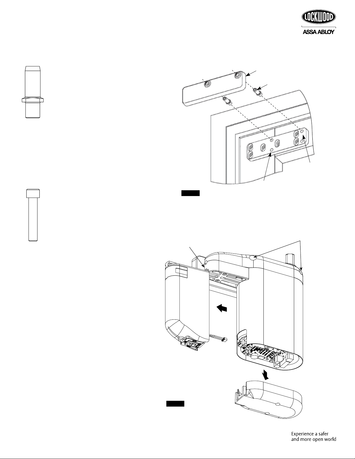
PUSH SIDE Operator and Arm Installation
Figure 5
Prepare Door and Frame
Figure 4
16mm Minimum
38mm Maximum
Greater than 38mm"
38mm Or Less
16mm Minimum
38mm Maximum
Operator Mounting Bracket
For Narrow Stile Doors
ADAEZ - LEFT HAND TEMPLATE - PUSH MOUNT
Operator Mounting Bracket
For All Other Doors
This device does not work with Swing
Clear hinges or Balanced Doors
Minimum Reveal - 40mm
Minimum Top Rail - 51mm
Stop Width - Reveal minus 25mm
Frame Face - No Minimum
0803AU-Rev 1
------------------------------------------------------------------------254mm - REFERENCE----------------------------------------------------------------------------
FOLD FOLD FOLD FOLD FOLD FOLD FOLD FOLD
FOLD FOLD FOLD FOLD FOLD FOLD FOLD FOLD
Centerline of Door Hinge or Pivot
NOT Edge of Door
16mm Minimum
387mm Maximum
Greater than 38mm
16mm Minimum
38mm Maximum
Greater than 38mm
Door Stop sizes greater
than 38mm width
Use this Fold Line
Fold Aligns with Top of Door
All other Door Stop sizes
Use this Fold Line
Fold Aligns with Top of Door
Door Arm Pivot Shoe Centerline
For Center Pivot Doors
Door Arm Pivot Shoe Centerline
For Butt Hung or Offset Pivot Doors
Copyright © 2020, ASSA ABLOY Australia Pty Limited. All rights
reserved. Reproduction in whole or in part without the express
written permission of ASSA ABLOY Australia Pty Limited is prohibited.
www.lockweb.com.au
CAUTION:
Desktop printers and
copiers can modify
scale if "actual size"
is not selected in
print or copy dialog.
Verify reference
dimension accuracy
before using.
RESETTING THE CONTROLLER
PROGRAMMING
PROGRAMMING TRANSMITTER
RESETTING THE CONTROLLER
1. and +PRESS HOLD “SELECT”
until 4 LEDs flash green.“ENTER”
door, “ENTER”2. CLOSE PRESS
door, “ENTER”3. OPEN PRESS
door, “ENTER”4. CLOSE PRESS
“ENTER”5. andPRESS HOLD
until LEDs go out
REFER TO MANUAL FOR MORE INFO
1. andPRESS HOLD “LEARN”
until 4 LEDs flash green.
2. the RF activation switch,PUSH
the LEDs shall flash green.
1. ,PRESS HOLD “ENTER”and
2. andPRESS RELEASE “RESET”
Figure 3