*Image used for illustration purposes only.
Install
Instructions 1.1. Mark the edge of your door at the desired height
of your handle.
1.2. We recommend around 900mm – 1100mm from
floor level, or at the centre of a lock rail on a
panel door. (Figure 1)
1.3. Using a spirit level, mark the door at the desired
lever height, continuing the line from the front of
the door, around the edge and onto the back of
the door. (Figure 2)
1.4. We recommend extending the line 100mm
onto each face of the door.
1. Marking the Door
3.1. If required, shorten tie bolts to suit door
thickness.
3.2. Ensure to cut so that the screw does not protrude
from the opposite rose once installed.
3. Prepare Tie Bolts
— if using face fix timber screws, proceed to step 4
4.1. Place the split spindles into the lock body from
either side of the door*.
4.2. Install the halves on either side of the door,
ensuring the levers function in the correct direction.
4.3. Insert male tie bolts through top and bottom of
back plate, OR
4.4. Affix wood screws at all fixing points.
4.5. Place the female sections in the opposite holes,
lining them up with the male thread.
4.6. Secure loosely by hand, then use a screwdriver
to hold the female section while tightening the
male section with a second screwdriver.
—
* Regular spindle also provided
4. Install Levers
Plate Passage Set
Standard
2. Install Latch & Striker Plate
As per supplier instructions.
Preferred product height
Wood Screws
Figure 2.
1.1. Mark the edge of your door at the
desired height of your handle.
1.2. We recommend around 900mm –1100mm from floor
level, or at the centre of a lock rail on a panel door.
(Figure 1)
1.3. Using a spirit level, mark the door at the desired lever
height, continuing the line from the front of the door,
around the edge and onto the back of the door.
(Figure 2)
1.4. We recommend extending the line 100mm onto each
face of the door.
1. Marking the Door
Figure 1.
Figure 2.
Preferred
product
height
2. Install Mortice Lock & Striker Plate
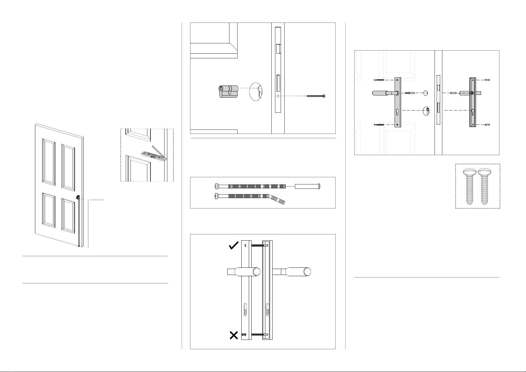
As per supplier instructions.
3.1. Insert key/ key euro cylinder through the lock
body and fix with the appropriately sized cylinder
screw provided. (Figure 3.)
—
*If you are installing a cylinder with thumb turn, please skip this
step and proceed to step 4.
**If required, refer to suppliers instructions.
3. Install Euro Cylinder (key/key only*)
Figure 3.
4. Prepare Cut-o Screws
— if using face fix timber screws, proceed to step 5
4.1. If required, shorten cut-o screws to suit door
thickness. (Figure 4.)
4.2. Ensure to cut so that the screw does not protrude
from the opposite rose once installed. (Figure 5.)
(1)
(4)
(5) Figure 4.
Figure 5.
5.1. Place the split spindles into the lock body from
either side of the door*.
5. Install Levers
5.2. Install the halves on either
side of the door, ensuring
the levers function in the
correct direction.
5.3. Insert male tie bolts through
top and bottom of back plate,
OR
5.4. Ax wood screws at all
fixing points.
Wood Screws
5.5. Place the female sections in the opposite holes,
lining them up with the male thread. (Figure 6.)
5.6. Secure loosely by hand, then use a screwdriver
to hold the female section while tightening the
male section with a second screwdriver.
—
* Regular spindle also provided
(1)
(4)
(2)
(3)
Figure 6.


