manuals.online logo
Brands
  1. Home
  2. •
  3. Brands
  4. •
  5. LOCKLY GUARD
  6. •
  7. Door Lock
  8. •
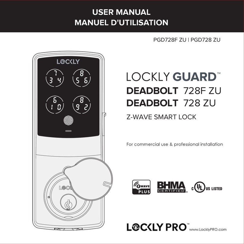
  9. LOCKLY GUARD ATHENA 228SL User manual

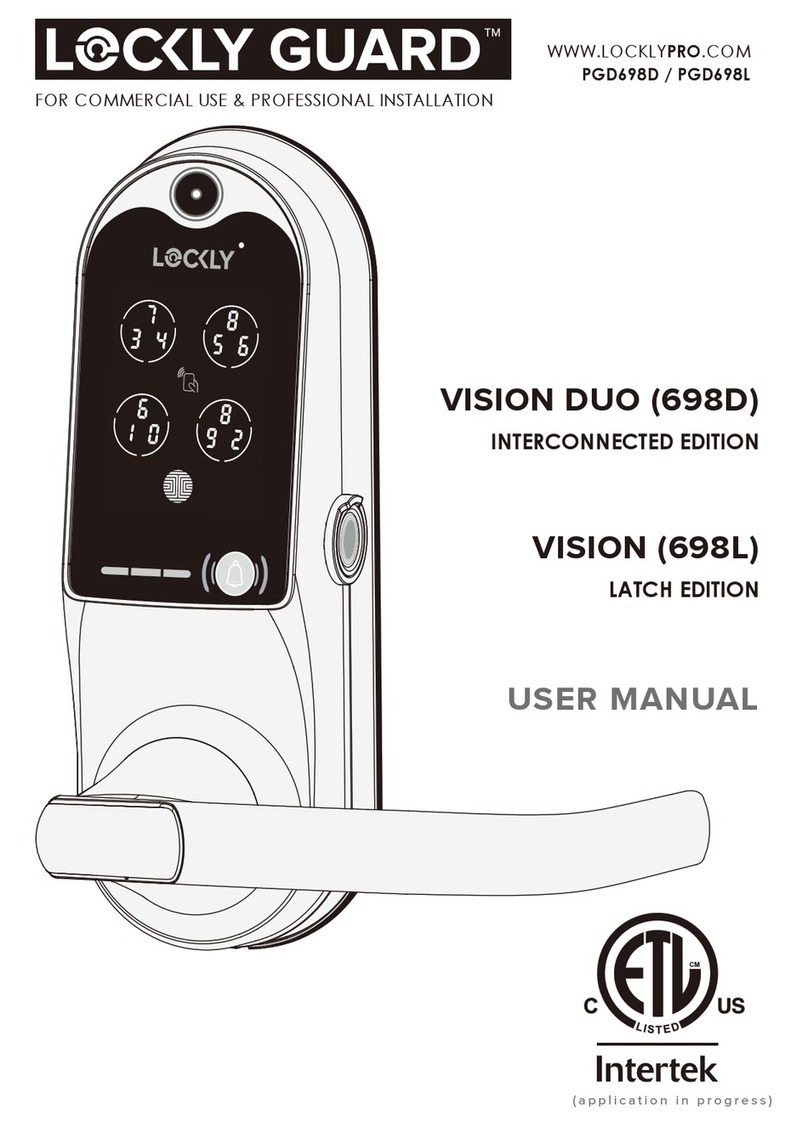
LOCKLY GUARD ATHENA 228SL User manual

REV͹0.3
ERP ߑֺ͹PL35R1UQ-GL-SMT00030A-V1
ݔଚ͹安装指引: PL35R1UQ/PGD228W,SMT000,REV.A(MPGD228W20220425),
140×190MM,80G书纸,双面单黑印刷,12页24面装订本,RoHS2.0,REACH,
Prop65,POPs,PAHs
ERP P/N:
Date: 2022-04-25
Designer͹Sunny
K
SLIDE & SWING EDITION
ATHENA (228SL)
(228SW)
FOR COMMERCIAL USE & PROFESSIONAL INSTALLATION
R
INSTALLATION
GUIDE
WWW.LOCKLYPRO.COM
PGD228W
INSTALLATION
GUIDE
Prepare door: remove existing deadbolt or use provided template to bore
new holes.
Installation template
Baseline approximately 1
meter from the ground
Ø25 Door Handle Hole
3
Preparation
4
DETERMINE DOOR OPENING DIRECTION
Step 1
RIGHT IN-SWING DOOR
RIGHT OUT-SWING DOOR
LEFT IN-SWING DOOR
LEFT OUT-SWING DOOR
There are 4 common door-opening directions, the lockset configuration as shown on each
diagram below corresponds to the respective door-opening direction.
This lock is designed for 35-65mm Wooden or Aluminium Door or Aluminium Thermal
Barrier Door. If your door is outside the range of the list above please contact our
Customer hotline: (669) 500-8835
Before installing the key cylinder and spindle, make sure you have already adjusted
your Latch throw (Step 2) and door handle (Step 3) according to door opening
direction.
IMPORTANT
Make sure the latch throw is
correctly oriented as shown
to fit your right in-swing door
Make sure the latch throw is
correctly oriented as shown
to fit your right out-swing door Make sure the latch throw is
correctly oriented as shown
to fit your left out-swing door
Make sure the latch throw is
correctly oriented as shown
to fit your left in-swing door
NOTE: If you're installing a Slide Edition, skip these steps and proceed to Step 3
5
Lockset ships default for RIGHT IN-SWING or LEFT OUT-SWING DOORS. Skip this procedure if
your door orientation is as stated. See Step 1 to determine your door opening direction.
Follow the step by step direction to adjust the lockset for LEFT IN-SWING or RIGHT
OUT-SWING DOORS.
Follow the below steps if you're installing ATHENA SWING EDITION with model and
backset size: PGMB118 1 1/8" (28mm), PGMB138 1 3/8" (35mm), PGMB158
1
5/8"(40mm), PGMB134 1 3/4"(45mm), PGMB238 2 3/8"(60mm)
NOTE: If you're installing a Slide Edition skip this step and proceed to Step 3.
If you're installing a Multi-Point Lockset for a Swing Edition, see next page to adjust the latch throw.
ADJUSTING THE LATCH THROW
Step 2
For your reference, a fully reversed
latch throw is shown.
Position and hold the lockset
as shown.
Move the metal barrier to
loosen the latch throw
Push the latch throw inside the lockset body.
Rotate the latch throw 180 degrees and
let the throw to fully extend out from
the
lockset after rotation.
1
2
4
3 5
1
2
3 5
4
6
Push the
button up
as shown
Default setting for these lockset models is for RIGHT IN-SWING or LEFT OUT-SWING DOORS.
Skip this procedure if your door orientation is as stated. See Step 1 to determine your door
direction.
Follow the step by step direction to adjust the lockset for LEFT IN-SWING or RIGHT OUT-SWING
DOORS.
FOR MULTI-POINT LOCKSET MODELS: PGMB138H 1 3/8" (35mm) / PGMB158H 1 5/8"
(40mm) / PGMB134H 1 3/4" (45mm)
ADJUSTING THE LATCH THROW
Make sure the push
button is in the position
as shown
Rotate
the latch
throw 180
degrees
Press the latch throw into
the
lockset, push the button
to reset, the latch throw
automatically
extended to
complete the reversal.
Step 2
continued
1
2
4
3
7
The diagram below shows how to shift the door handle from right to left direction. The default
setting of the handle is for right handed door. You do not need to change direction if you
have a right handed door.
Default
(on
the right)
After the handle screw
is loosened, remove the
handle.
After the handle
screw is loosened,
remove the handle
Rotate handle
180° and fasten
the screw inside
the handle to
secure.
Rotate handle 180°
and fasten the screw
inside the handle to
secure.
CHANGING HANDLE FOR RIGHT OR LEFT SWING DOORS
Step 3
Loosen the
screw inside
the handle
Loosen the
screw inside
the handle
1 2 3
1 2 3
Change the handle direction of the Exterior Panel
Change the handle direction of the Interior Panel
For Right swing door
align handle to "R"
For Left swing door
align handle to "L"
Ensure the handle is correctly
positioned according to desired
direction (L/R)
IMPORTANT
8
Adapter Positioning Screw (x1)
KM5x35mm
PGMB118 1 1/8" (28mm)
PGMG118 1 1/8" (30mm)
PGMG118H 1 1/8" (30mm)
KM5x40mm
PGMB138 1 3/8" (35mm)
PGMB138H 1 3/8" (35mm)
PGMG138 1 3/8" (35mm)
PGMG138H 1 3/8" (35mm)
KM5x45mm
PGMB158 1 5/8"(40mm)
PGMB158H 1 5/8"(40mm)
KM5x50mm
PGMB134 1 3/4"(45mm)
PGMB134H 1 3/4"(45mm)
KM5x65mm
PGMB238 2 3/8"(60mm)
H
Lockset Screws
KA4X25mm (x2)
Make sure your door is prepared for installation. If you need to drill new holes, please use the
supplied template for drilling holes. Before installing the Lockset S, confirm the door opening
direction (Step 1) and ensure latch throw inclined part is positioned opposite to the opening
direction.
INSTALLING THE LOCKSET
Step 4
Insert Lockset onto door hole and secure with screws H(top and bottom) & F .
Baseline approximately
1m above ground
01
12
2
012345678910
01
12
2
012345678910
Installation template
Hole for handle
Positioning Clamp
Cylinder Adapter (x1)
F
F
E
Cylinder Adapter (x1)
Step 4
continued
9
INSTALLING THE LOCKSET
Insert cylinder adapter E
make
sure the arrow (red
mark)is at the
bottom as shown.
Once adapter is secured, remove
positioning clamp by pressing on
both sides.
Use positioning clamp to
hold the
cylinder adapter
in "+" position.
3
1
2
4
To check if the cylinder adapter is properly
installed, insert a phillips screwdriver. Turn
clockwise and counter clockwise to check
is the deadbolt and latch throw fully extend
and retract. You may need to adjust the
position if of the adapter if the deadbolt
and latch throw are not fully extending
and
retracting.
E
10
M4 Slotted Barrel
Extension (x1)
ATTACHING EXTERIOR PANEL INSTALLATION PARTS
Step 5
Before installing the key cylinder, make sure your door handle have been adjusted to your
door opening direction, see Step 2.
Install Key Cylinder O
1. Measure door thickness and cut off the key cylinder blade (if necessary).
2. Insert key cylinder Oto exterior panel.
3. Secure the cylinder with screws G(x2) on both sides.
4. Insert M4 slotted barrel extension according to lockset
dimension.
If door thickness is between
35-45mm, cut off and discard
this portion (3rd scale to end)
1rd
2rd
Lock Cylinder(X1)
KM4X6mm Screws(x2)
* If door thickness is more than 45mm,
you don't need to cut the blade.
PGD228WSWSS-28;
PGD228WSWSS-40;
PGD228WSWSS-60
For Athena Swing Edition with locksets:
PGMG118 & PGMG118H 1 1/8" (30mm)
and PGMB138H 1 3/8"(35mm)
M4 Slotted Barrel
Extension (x1)
M4 Slotted Barrel
Extension (x2)
For Athena Swing Edition with locksets:
PGMB118 1 1/8" (28mm) and
PGMB138 1 3/8" (35mm)
For Athena Swing Edition with locksets:
PGMB158 1 5/8" (40mm) and PGMB134 1 3/4" (45mm);
For Athena Slide Edition with locksets:
PGMB138H 1 3/8" (35mm), PGMB158H 1 5/8" (40mm),
PGMB134H 1 3/4"(45mm)
O
G
M1
M1
M1
Install Spindle A
1. Select spindle A1/A2 according to door thickness.
2. Install at the center hole of the exterior panel.
3. Insert cotter pin and bend both ends.
IMPORTANT: Ensure the handle is correctly positioned
according to desired direction (L/R) before bending
the ends of the cotter pin.
Step 5
continued
11
Spindle(X1)
Cotter Pin(X1)
D
ATTACHING EXTERIOR PANEL INSTALLATION PARTS
M2 + M4 Accessories for 35-55mm Door Thickness
M3 + M4 Accessories for 56-80mm Door Thickness
* Other door thickness accessories need to be customized
Before installing the key cylinder, make sure your door handle have been adjusted to your
door opening direction, see Step 2.
The illustration below applies for lockset : PGMB238 2 3/8" (60mm), Athena Slide Edition
M4 Slotted Barrel Extension(X1)
Spindle(X1)
Cotter Pin(X1) D
Lock Cylinder(X1)
KM4X6mm Screws(x2)
For Right swing door
align handle to "R"
For Left swing door
align handle to "L"
Bend the ends
of cotter pin
A1 A2
M4
A
O
G
M2 Accessories for 35-55mm Door Thickness
M3 Accessories for 56-80mm Door Thickness
12
Before installing the key cylinder, make sure your door handle have been adjusted to your
door opening direction, see Step 2.
The illustration below applies for All Athena Slide Edition lockset : PGMB118 1 1/8" (28mm),
PGMB138 1 3/8" (35mm).
The illustration below applies for lockset : PGMB238 2 3/8" (60mm), Athena Slide Edition
Step 5
continued
Note: When installing PGMB238 2 3/8" (60mm) lockset,
assemble M4 screw with the interior panel.
M4M4 Slotted Barrel
Extension(x1)
M2 M3
U
Spacer(x1)
Turn over the
silicone sheet
Spacer Screws
KM4x8mm(x1) T
ATTACHING EXTERIOR PANEL INSTALLATION PARTS
U
Spacer(x1)
Turn over the
silicone sheet
Spacer Screws
KM4x8mm(x1) T
Install the exterior panel onto door. Ensure the spindle, lock cylinder, positioning rods and
cable are inserted on the correct holes and passed through the llockset.
INSTALLING THE EXTERIOR AND INTERIOR PANEL
13
Step 6
Plug the connection cable of the exterior panel to
cable of the interior panel. Once connected insert
cable to the door frame holes.
Install the interior panel and secure with screws Band C
Ensure the cables are panels are completely plush flat
on the door surface. Use screw caps N to cover B
screws.
Escutcheon Screw (x2) B
Door Thickness 30-50mm: KM5x46mm
Door Thickness 51-65mm: KM5x61mm
Door Thickness 66-80mm: KM5x76mm
Escutcheon Screw(x1) C
Door Thickness 30-50mm: PM4x28mm
Door Thickness 51-65mm: PM4x43mm
Door Thickness 66-80mm: PM4x58mm
While you are inside the house, try to close and open the door. Check if the deadbolt and
latchbolt fits the door frame holes and the door closes properly.
INSTALL DOOR FRAME AND STRIKE
Step 7
14
Allen wrench 2.5mm (x1)
When the strike plate is fixed on the door frame, the 2 screws should be adjusted to the inner
side of the unlocking hook about 1-2mm. After the screws are locked, the surface of the
exposed screws should not be lower than the surface of the strike plate.
Wood door frame or non-broken bridge aluminum
metal door frame require drilling drilling template. see
illustration on the left for locksets: PGMG118 1-1/8"
(30mm), PGMG118H 1-1/8" (30mm), PGMG138 1-3/8"
(35mm), PGMG138H 1-3/8" (35mm)
Wood/aluminum door frames requires drilling. Use
template to drill holes and install the strike plate.
secure the strike with screws.
Broken bridge aluminum do not require drilling to
nistall strike plate, directly install onto door frame
and secure with screws.
Door Frame
Door Frame
Door Frame
Z
J
KA4x16mm Screws(X4)
KA4x16mm Screws(X4)
I
Strike Plate
Strike Plate
J L
KA4x16mm Screws(X4)
KA3x16mm Screws(X4)
I
I
KI
K
PREPARING DOOR SENSOR FOR INSTALLATION
Step 8
15
Lockly Guard Athena comes with a pre-wired door sensors consisting of two parts:
Part (V) - Wired Sensor Part (W) - Sensor Magnet
About door sensors
Door sensors provide real-time door condition status, such as the ability to verify if the door
is securely closed. It sends push notifications to your phone whenever your door opens.
Removal of Sensor (optional)
There may be circumstances where the sensor cannot be installed because of molding/door
limitations or is not aesthetically desirable. The sensor wired to the lock is removable by
c
arefully pulling its connector from the circuit board. If removed, some features and
functionality will not be available, such as real-time condition status.
IMPORTANT: Gap must be less than 3/4” when installed.
When installed on door, the distance between the wired sensor
and sensor magnet must be less than 3/4” in order for the sensor
to work. If door frame is higher than door, add included foam
pads to level parts (V) and (W) with each other as much as
possible.
TIP:
Lockly Guard door sensors comes in Grey (PGA715) and Matte Black (PGA716)
that
can be ordered through our customer hotline: +1 (855) 562-5599 or by
email:
[email protected].
The arrows must be aligned or as closed as possible (less than 3/4"). If
needed, adjust the position of the sensor magnet using provided foam
pads to ensure the Lockly logo blinks red when door opens or closes.
IMPORTANT:
16
INSTALLING DOOR SENSORS
Step 8
continued
1、Peel off the paper layer of the
adhesives from the back of the wired
sensor.
3、Close the door. Before you peel off the paper layer of the adhesives from the sensor
magnet, align the arrow with the wired sensor. Install on to door frame.
2、Position the wired sensor to the edge of
the door, avoiding the door strike plate.
Attach and secure with the adhesives.
Peel off the paper layer
of the adhesives from the
back of the wired sensor.
peel off
Foam Pads
X
1. Open the battery compartmebt and insert 4 AA batteries. Make sure the batteries are
correctly positioned.
Battery cover
Battery X4
2. Check the lock functions according to
user manual after installing the batteries.
Use the battery cover to secure the battery
compartment and fasten with screw.
Tighten the front and rear
panel fixing screws (B) and
fasten the silicone plugs (N);
Note: Please confirm that
the installation is successful
and the function is normal,
and then fasten the silicone
plug.
After removing the battery door
with a screwdriver, put the battery
on, and then tighten the battery
door with a screwdriver.
FINAL CHECK AND BATTERY INSTALLATION
Step 9
17
Congratulations! You have completed the Lockly Guard physical lock installation. To
complete your setup, download the LocklyPro app from the iOS or Google Play app Store
and follow on-screen instructions.
Scan or visit
Locklypro.com/app
18
DOWNLOAD LOCKLY APP
Step 10
FCC Warning:
This device complies with Part 15 of the FCC Rules. Operation is subject to the following two condi-
tions: (1) This device may not cause harmful interference, and (2) this device
must accept any
interference received, including interference that may cause undesired
operation.
NOTE 1: This equipment has been tested and found to comply with the limits for a Class
B digital
device, pursuant to part 15 of the FCC Rules. These limits are designed to provide
reasonable protec-
tion against harmful interference in a residential installation. This
equipment generates, uses and
can radiate radio frequency energy and, if not installed and used in accordance with the instruc-
tions, may cause harmful interference to radio communications. However, there is no guarantee
that interference will not occur in a particular installation. If this equipment does cause harmful
interference to radio or television reception, which can be determined by turning the equipment
off and on, the user is encouraged to try to correct the interference by one or more of the following
measures:
- Reorient or relocate the receiving antenna.
- Increase the separation between the equipment and receiver.
- Connect the equipment into an outlet on a circuit different from that to which the receiver is
connected.
- Consult the dealer or an experienced radio/TV technician for help.
NOTE 2: Any changes or modifications to this unit not expressly approved by the party responsible
for compliance could void the user's authority to operate the equipment.
FCC Radiation Exposure Statement
Lockly Guard Link+ complies with FCC radiation exposure limits set forth for an uncontrolled
environment. It should be installed and operated with minimum distance 20cm between the
radiator & your body.
IC WARNING
This device contains licence-exempt transmitter(s) that comply with Innovation, Science
and
Economic Development Canada’s licence-exempt RSS(s). Operation is subject to
the following
two conditions:
(1) This device may not cause interference.
(2) This device must accept any interference, including interference that may cause undesired
operation of the device.
L’émetteur/récepteur exempt de licence contenu dans le présent appareil est conforme aux CNR
d’Innovation, Sciences et Développement économique Canada applicables aux appareils radio
exempts de licence. L’exploitation est autorisée aux deux conditions suivantes:
1. L’appareil ne doit pas produire de brouillage;
2. L’appareil doit accepter tout brouillage radioélectrique subi, même si le brouillage est suscepti-
ble d’en compromettre le fonctionnement.
IC Radiation Exposure Statement
This equipment meets the exemption from the routine evaluation limits in section 2.5 of RSS-102. It
should be installed and operated with a minimum distance of 20cm between the radiator and any
part of your body.
Cet équipement est conforme à l'exemption des limites d'évaluation habituelle de la section 2.5 de
la norme RSS-102. Il doit être installé et utilisé à une distance minimale de 20 cm entre le radiateur
et toute partie de votre corps
WARNING: This product can expose you to chemicals including Lead, which is known to the
State of California to cause cancer. For more information go to www.P65Warnings.ca.gov.
Z
Strike Plate (x1)
J L
I K
INSTALLATION OVERVIEW AND PARTS LIST
Parts List
Labeled As Description
Parts List
Labeled As Description
A
Spindle (x1)
A1 Door Thickness 35-50mm: Spindle 62mm (x1)
A2 Door Thickness 51-65mm: Spindle 77mm (x1)
B
Escutcheon Screw (x2)
Door Thickness 30-50mm: KM5x46mm
Door Thickness 51-65mm: KM5x61mm
Door Thickness 66-80mm: KM5x76mm
Escutcheon Screw (x1)
Door Thickness 30-50mm: PM4x28mm
Door Thickness 51-65mm: PM4x43mm
Door Thickness 66-80mm: PM4x58mm
C
D Cotter Pin (X1)
E Cylinder Adapter & Clamp (x1)
F Adapter Positioning Screw (x1)
G KM4X6mm Screws (x2)
H KM4x25mm Screws (x2)
IWooden Door / Aluminum Thermal Barrier
Door KA4x16mm Screws (x4)
J / L Strike Plate(x1)
K Aluminum Door KA3x16mm Screws(x4)
N Silicone Screw Caps (x2)
M
O
M4 (x1)
M1 (x2)
Key Cylinder (x1) + Keys (x5)
PExterior Panel
Q
RActivation Card
SMortise Lockset
TKM4X8mm Screws (x1)
USpacer (x1)
VWired Sensor
WSensor Magnet
XFoam Pads
YBattery cover
Z
A
T
U
EM
O
G
H
S
V
X
W
P
Q
B
C
Y
N
F
R
D
Exterior
门框
Interior Panel

This manual suits for next models

1

Other LOCKLY GUARD Door Lock manuals

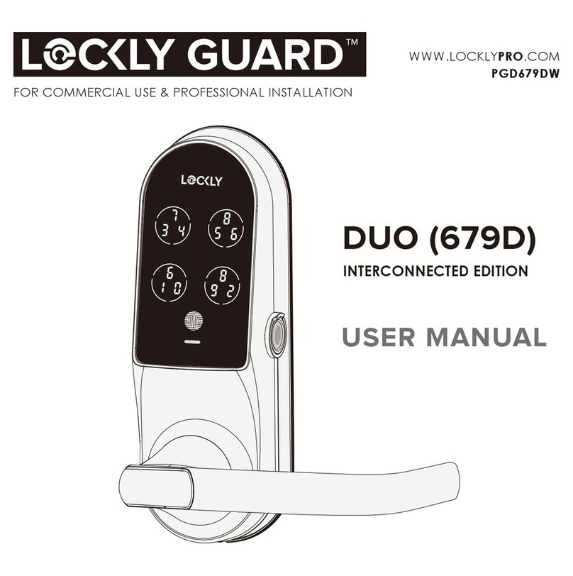
LOCKLY GUARD DUO INTERCONNECTED EDITION User manual

LOCKLY GUARD

LOCKLY GUARD DUO INTERCONNECTED EDITION User manual

LOCKLY GUARD VISION DUO User manual

LOCKLY GUARD

LOCKLY GUARD VISION DUO User manual

LOCKLY GUARD DEADBOLT 728F Z User manual

LOCKLY GUARD

LOCKLY GUARD DEADBOLT 728F Z User manual

LOCKLY GUARD DEADBOLT 728F ZU User manual

LOCKLY GUARD

LOCKLY GUARD DEADBOLT 728F ZU User manual

LOCKLY GUARD VISION DUO User manual

LOCKLY GUARD

LOCKLY GUARD VISION DUO User manual

LOCKLY GUARD DEADBOLT 728Z User manual

LOCKLY GUARD

LOCKLY GUARD DEADBOLT 728Z User manual

LOCKLY GUARD 698L User manual

LOCKLY GUARD

LOCKLY GUARD 698L User manual

LOCKLY GUARD DEADBOLT 728F Z User manual

LOCKLY GUARD

LOCKLY GUARD DEADBOLT 728F Z User manual

LOCKLY GUARD DEFENDER SLIDE EDITION User manual

LOCKLY GUARD

LOCKLY GUARD DEFENDER SLIDE EDITION User manual

LOCKLY GUARD DEFENDER 238LM User manual
LOCKLY GUARD

LOCKLY GUARD DEFENDER 238LM User manual

Popular Door Lock manuals by other brands

Assa Abloy ESA500 Programming instructions

Assa Abloy

Assa Abloy ESA500 Programming instructions

GATEMASTER BQK1030L manual

GATEMASTER

GATEMASTER BQK1030L manual

Griffwerk SMART2LOCK 2.0 Mounting instructions

Griffwerk

Griffwerk SMART2LOCK 2.0 Mounting instructions

Assa Abloy 179A Mounting instruction

Assa Abloy

Assa Abloy 179A Mounting instruction

Stanley EL manual

Stanley

Stanley EL manual

Signature Hardware PIRAN 953389-DU-LH manual

Signature Hardware

Signature Hardware PIRAN 953389-DU-LH manual

Satel INT-SZK manual

Satel

Satel INT-SZK manual

ERA TS003 Fitting instructions

ERA

ERA TS003 Fitting instructions

Bewator K44 Duo Installation & user manual

Bewator

Bewator K44 Duo Installation & user manual

Specialty Carts CompX eLock Quick programming guide

Specialty Carts

Specialty Carts CompX eLock Quick programming guide

EUCHNER EKS2 operating instructions

EUCHNER

EUCHNER EKS2 operating instructions

Hewi mini installation instructions

Hewi

Hewi mini installation instructions

Assa Abloy effeff Mini Shear Magnet Mounting instructions

Assa Abloy

Assa Abloy effeff Mini Shear Magnet Mounting instructions

Schlage Connect Smart Deadbolt quick start guide

Schlage

Schlage Connect Smart Deadbolt quick start guide

DynaLock 1661 Series installation instructions

DynaLock

DynaLock 1661 Series installation instructions

Salto LC1M Series quick start guide

Salto

Salto LC1M Series quick start guide

Dormakaba ED22 installation instructions

Dormakaba

Dormakaba ED22 installation instructions

Philips EasyKey 7000 Series user manual

Philips

Philips EasyKey 7000 Series user manual

manuals.online logo
manuals.online logoBrands
  • About & Mission
  • Contact us
  • Privacy Policy
  • Terms and Conditions

Copyright 2025 Manuals.Online. All Rights Reserved.