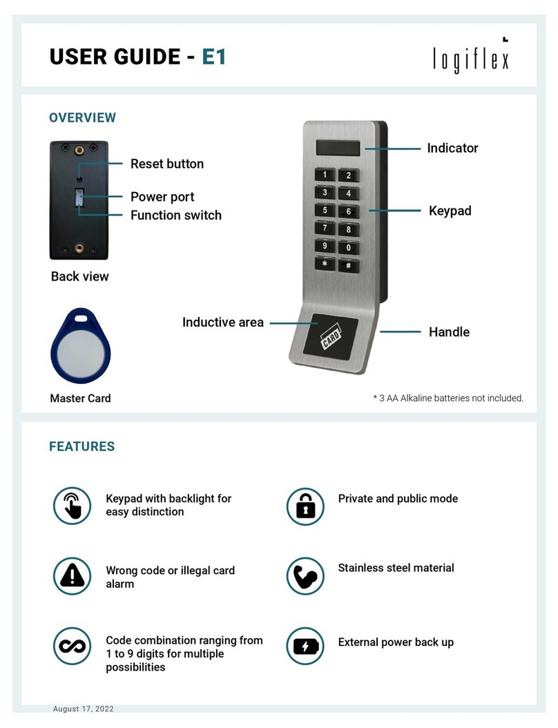
Logiflex E1 User manual

USER GUIDE
E1 Lock
OVERVIEW
FEATURES
• Backlit keyboard when in use for easy reading;
• Stainless steel material;
• 2 types of use: private or public;
• External emergency power supply;
• Codes ranging from 1 to 9 digits for multiple possibilities;
• 20-second alarm when an incorrect code or card is used 4 consecutive times;
• Possibility of user card, sold separately
ITEMS
• Lock (included);
• Chip (included);
• User card (not included);
• Emergency battery charger
(not included).

1
1
1
1
1
3
11
2
3
4
1
2
1
4
3
2
1
1
5
1
1
OVERVIEW
Front case, front view
1. Green or red indicator
2. Keyboard
3. Handle
4. Inductive zone
5. Emergency power port
Front case, back view
1. Reset button
2. Plug hole
3. Switch for functionality (private or public)
Rear case
1. Power plug
2. Latch
3. Battery holder
4. 3 AA alkaline batteries (not included)

1
1
ASSEMBLY INSTRUCTIONS
**IMPORTANT**
Determine the desired type of use BEFORE the initialization
Determine the desired type of use (private or public) and
position the switch at the back of the lock according to the
desired use. By default, the lock is in position 2 (Switch to
the lef).
Position 2 : Private use
The switch must be positioned on the left. This mode is
suitable in a shared locker or unassigned locker context. The
code is valid for one use only and the door remains unlocked
between each use.
Position 1 : Public use
The switch must be positioned on the right. This mode is
appropriate in a locker room context assigned to a person.
Assign a permanent code and the door locks automatically
after opening.
Batteries AA
Load 3 AA alkaline batteries (not included) into the battery holder
.
Case
Insert the plug of the rear case into the socket of the front case.
Initialization
Use a small sharp tool (one of the included screws can work)
to press the reset button until 3 long beeps sound, indicating
the lock has been successfully initialized. Remove the batteries
to x the cases. After xing the 2 cases on the locker door,
reinsert the batteries After initialization, if any cards or digital
codes had previously been programmed for this lock, they will
be deleted.

1
1
1
USER GUIDE
Master chip
To be able to use the E1 electronic lock, one of the chips must be programmed as the master chip.
The master chip is used to:
• Unlock different locks from the same chip;
• Program or delete lock codes;
• Program or delete user cards.
Note that it is also possible to program a user card, sold separately, as a master card following the same procedure.
Programming a master chip
After lock initialization, put the chip on the inductive zone.
After 3 long beeps and ashes of the green indicator, the
programmed chip becomes the master chip.
During the red indicator ashing period, up to 2 more chips
can be added as master chips.
The programming of 3 master chips is recommended in case
chips are lost.
To program a new master chip while the red indicator is
ashing, the programming procedure is:
* -> master chip -> # -> new master chip.
Maximum of 3 master chips. After programming a 4th master
chip, the 1st master chip that was programmed is deleted.
Use a master chip
Put the master chip to the inductive zone. The green indicator
comes on with a beep and the lock is unlocked.
• In private use (position 1), the red indicator comes on for 5
seconds, then the lock locks automatically.
• In public use (position 2), the lock remains unlocked.

1
1
1
2x
1
3x
1
USER GUIDE
Lock with permanent code - Private use
Program the digital code
**IMPORTANT**
For private use, the switch must have been placed in
position 1 (switch on the right) at the time of installation.
Put the master chip on the inductive zone. After a beep, the
lock is unlock and the red indicator will blink. Scan the master
chip on the inductive zone again.
While it is blinking, enter a 1-to-9-digit code, then press #.
After a long beep, the code you entered becomes the
permanent code for this lock.
To delete the permanent code, scan the master chip on the
inductive card zone 3 times. 3 short beeps will conrm that
the permanent code is deleted.
Use the digital code
Enter the previously programmed permanent numeric code,
followed by #.
The lock unlocks and the red indicator comes on.
After 5 seconds the lock will automatically lock.

1
1
1
USER GUIDE
Lock with single use code - Public use
Program the digital code
**IMPORTANT**
For public use, the switch must have been placed in
position 2 (switch on the left) at the time of installation.
The master chip programming step is necessary, even for
public use.
Use the digital code
To lock the lock, keep the door closed and enter a 1 to 9 digit
numeric code followed by #.
The red indicator ashes followed by 2 beeps while the lock
locks.
To unlock the lock, enter the same digital code followed by #.
The locker will be unlocked and will remain unlocked for the
next use.

1
1
1
1
1
3x
x
x 5
1
USER GUIDE
Lock with user card - Private or public use
User card not included.
The user card is used to replace the use of a code. It can be used in 2 types of use: private or public.
Program a user card
**IMPORTANT**
Determine the type of desired use BEFORE installation
The master chip programming step is necessary.
Scan the master chip on the inductive zone. After a beep, the
red indicator will blink: scan the master chip again.
While it is blinking, scan a card on the inductive zone. After a
beep, the programmed card becomes a user card attributed
to this specic lock.
You can program up to 120 user cards, one after the other, for
a same lock.
To delete user cards, pass the master chip over the inductive
zone three times. After 3 long beeps, all user cards are
deleted.
Use a user card
Lock
• Put the user card on the inductive zone. The green indicator
comes on with a beep indicating that the door is unlocked.
Unlock
• In private use (position 1) after being unlocked, the red
indicator comes on for 5 seconds, then the lock locks
automatically.
• In public use (position 2), put the user card over the
inductive zone to lock the door. 2 beeps with the red

1
8x
BATTERY CHANGE
Battery
When the batteries begin to run low, the lock will emit a signal
during use by the user. The red indicator will ash and 8 beeps
will sound to indicate that the batteries need to be replaced.
Charger
If the batteries are exhausted, a 6V emergency battery
charger can be used. Insert the battery plug into the lock’s
power port, then enter the code or swipe the card on the
magnetic reader to unlock.
Table of contents
Other Logiflex Lock manuals
Popular Lock manuals by other brands

Motormate
Motormate Yamaha 10-303 SHO installation instructions

Command access
Command access CL93 installation instructions

StarTech.com
StarTech.com LTULOCK4D quick start guide

Schlage
Schlage F-Series installation instructions

Allegion
Allegion Interflex IF-191 Series manual

Isotra
Isotra DFC 10 quick start guide