Look T20 User manual

MA
NUAL
T20


IMPORTANT INFORMATION
PRODUCT INTRODUCTION
INSTALLING THE FORK
INSTALLING THE FRONT WHEEL FITTINGS
ASSEMBLING THE STEM
MOUNTING THE HANDLEBARS ON THE STEM
ANGULAR ADJUSTMENT I REMOVING THE STEM
ZED CRANKSET FEATURES
INSTALLING THE ZED CRANKSET IN THE FRAME
MOUNTING THE CHAINRINGS
INSTALLING THE SADDLE CLAMP
INSTALLING THE SEATPOST
INSTALLING THE REAR WHEEL
INSTALLING THE STIFFENERS
MAINTENANCE
CUSTOMER SERVICE
WARRANTY
> 4
> 4
> 5
> 6
> 11
> 13
> 14
> 15
> 16
> 18
> 20
> 23
> 25
> 30
> 31
> 31
> 31
EN

4
EN
LOOK products are protected by industrial
property rights.
For more information, please refer to
www.lookcycle.com/patents
Your frame has been manufactured according to the technical specications of the LOOK engineering
department.
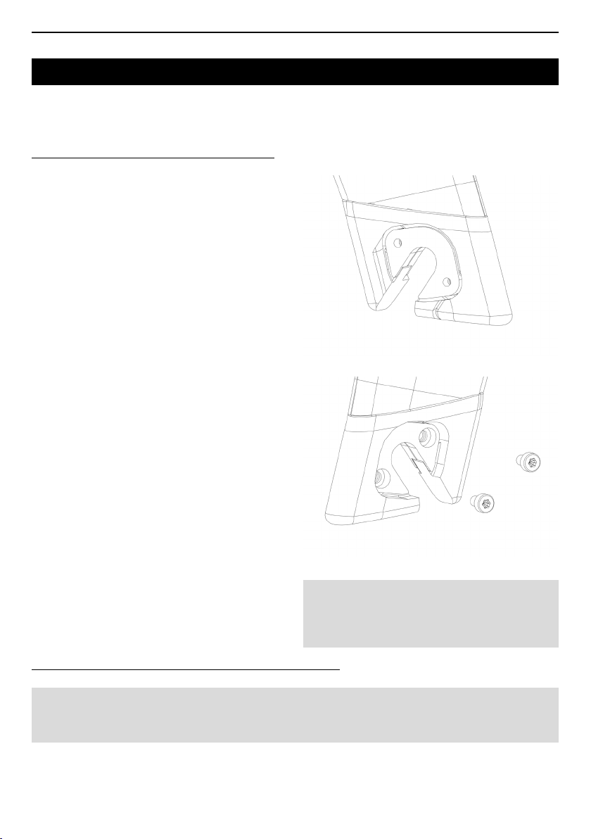
Your frame is delivered with a ZED crankset specially developed for track cycling, an offset fork, a carbon
track stem and aero carbon handlebars.
The frame also comes with a proled seatpost and two carbon saddle clamps.Your T20 bike is compatible
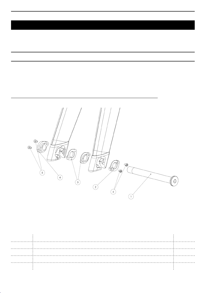
with standard and thru-axle front and rear wheels.
Warning : LOOK products are designed and
optimised for cyclists weighing no more than
100kg (220,5 lbs).
Counterfeit product warning: Using
counterfeit products is extremely dangerous
as these can fail and cause you or third parties to
fall, resulting in serious injury or even death.
PRODUCT INTRODUCTION
IMPORTANT INFORMATION
Before riding, please read these instructions
carefully and respect the recommendations in
order to fully enjoy this beautiful product!
We highly recommend you ask your LOOK
retailer for advice regarding installation and
assembly.
In a constant effort to improve performance,
LOOK reserves the right to modify product
specications without prior notice.
For more information, please refer to our website
www.lookcycle.com, WARRANTY POLICY >
COUNTERFEIT.
For more in-depth details related to IMPORTANT
INFORMATION, please refer to our website
www.lookcycle.com, WARRANTY POLICY >
IMPORTANT INFORMATION.
If you are unable to access our website, your
LOOK retailer can provide you with a print
version of our warranty policies.
!
!

5
EN
When assembling, disassembling and/or servicing
your bicycle, please refer to the diagram below to
ensure all the headset parts are in the correct posi-
tion and order.
* Upper parts 3, 4 & 5 are delivered pre-assembled.
* Lower part 5 is delivered tted into the fork.
*The steerer tube (9) ts into the frame.
Note : The CHC M8x20 screw (1) must be coated
with a medium threadlocker such as LOCTITE
243TM and tightened to a torque of 8 Nm
1CHC M8x20 screw - Allen HEX 6 - 8Nm -
threadlocker ex.: LOCTITE 243 x1
2Steerer tube I stem spacer x1
3Headset cap x1
4Spacer 6.2x1* x1
5Needle roller bearing* x2
6Steerer spring block x2
7
Piston seal
x2
8
Steerer spring
x2
9
Steerer tube*
x2
10
Spacer 9.5x1.5
x1
INSALLING THE FORK

6
EN
INSTALLING THE FRONT WHEEL FITTINGS
In the case delivered with your bike, you will nd a bag containing all the necessary parts to install the ttings
compatible with your wheels.
These ttings allow you to mount a Ø12mm, at seat thru axle or a standard axle depending on the type of
wheels used.
EXPLODED VIEW OF THE FRONT WHEEL FITTINGS FOR A Ø12MM THRU AXLE
112mm front thru axle - Allen HEX 6 - 10Nm - greased x1
2Smooth washer x1
3Threaded washer x2
4M12 nut x1
5M3x5 screw - Torx T10 - 1Nm - threadlocker ex.: LOCTITE 243 x4

7
EN
1ISet aside all the parts you will need for your selected build.
2IClean and degrease the parts and the fork ends with a suitable degreaser, excluding the M3x5mm
screws already coated with threadlocker.
3IPrepare a torque wrench with both HEX 6 and TORX T10 heads.
EXPLODED VIEW OF THE FRONT WHEEL FITTINGS FOR A STANDARD AXLE
BEFORE ASSEMBLING
1Smooth washer, diameter 10 x2
2Threaded washer, diameter 10 x2
3M3x5 screw - Torx T10 - 1Nm - threadlocker ex.: LOCTITE 243 x4

8
EN
1IPlace the threaded washer on the inside of the
left fork end and press it rmly into place.
2IPlace the smooth washer on the outside of the
left fork end and press it rmly into place. Pre-tighten
using 2 M3x5 screws.
3IRepeat step 1 on the right side (the threaded
washer is a symetrical piece and can be mounted
on either side).
4IInsert the M12 nut on the outside of the right fork
end and press it rmly into place. Pre-tighten using
2 M3x5 screws.
INSTALLING THE THRU AXLE FITTINGS
Inside
Outside
Outside

9
EN
5IBefore tightening the 4 screws completely, grease
the thread of the thru axle and screw it partly into
the M12 nut while still allowing access to the M3x5
screws. This will ensure that the ttings are aligned.
Remove the thru axle and tighten all 4 M3x5 screws
to a torque of 1 Nm.
6 I Grease the thru axle thread. Install the wheel
and tighten the axle (H6 Allen wrench) to a torque
of 10Nm.
WARNING : Ensure the screw heads do not
protrude beyond the counterbore, or the axle will
rest on the screw heads rather than on the at
surface of the washer.

10
EN
1IPlace the threaded washer on the inside of the
left fork end and press it rmly into place.
2IPlace the smooth washer on the outside of the
left fork end and press it rmly into place. Using 2x
M3x5 screws, tighten to a torque of 1Nm.
3IRepeat steps 1 & 2 on the right fork end (the
washers are symmetrical and can be mounted on
both the right and left hand side).
INSTALLING THE STANDARD AXLE FITTINGS
IMPORTANT CONSIDERATION FOR ALL SETUP OPTIONS
Inside
Outside
WARNING : Ensure the screw heads do not
protrude beyond the counterbore, or the axle will
rest on the screw heads rather than on the at
surface of the washer.
Using wheels with different axle types requires swopping the ttings regularly. After assembling/
disassembling three times it is important to recoat the screw threads with a standard threadlocker
such as LOCTITE 243TM. Do not grease or lubricate the screws !

11
EN
ASSEMBLING THE STEM
1Right hand cone x1
2FHCX M5x30 screw - Torx T25 - 8Nm - threadlocker ex.: LOCTITE 243 x3
3Headset cap x1
4M6x10 extraction screw - Allen HEX 5 x1
5FHCX M5x30 screw - Torx T25 - 8Nm - threadlocker ex.: LOCTITE 243 x3
6Left hand cone x1
7Stem x1
8CHC M5x30 screw - Allen HEX 4 - 8Nm - threadlocker ex.: LOCTITE 243 x2
9Handlebars x1
10 Stem face plate x1
11 Plate barrel x1

12
EN
2IGrease the M6x10 extraction screw (4).
1IDegrease the cones (1 & 6), the headset cap (3)
and the stem with a clean cloth.
3IManually screw the M6x10 screw into the left
cone and tighten until it rests on the small diameter
of the cone.
4ILine up the cones in the headset cap. The hole in
the right hand cone must be aligned with the thread
of the left hand cone.
5 I Apply light pressure to the cones to ensure
they stay in place in the headset cap. The cones
must not protrude from the headset cap before
mounting the stem.
6IPosition the stem on the headset cap.
7 I Align the holes in the stem with the holes in the
cones. Then pre-tighten the 6 M5x30 screws
(coated in threadlocker such as LOCTITE 243) to
hold the stem in place.
8 I Adjust the stem angle. Stem angles can vary
between +20° and -9° (horizontal reference).
9IEvenly tighten each of the FHCX M5x30 screws
to a torque of 8Nm using a torque wrench with a T25
head. To ensure the screws are evenly tightened,
alternately tighten the left and right screws.
The right hand screws go through the right side of
the stem and tighten into the left cones and vice
versa.

13
EN
MOUNTING THE HANDLEBAR ON THE STEM
1IDegrease the face plate (10), the handlebars (9)
and the stem (7).
2IGrease the M5x30 screw (8) threads and heads.
3IPlace the barrel in the face plate. The barrel sits
under the stem (see diagram opposite).
4IPre-position the handlebar in the stem.
5IPlace the lower part of the face plate against
the stem.
6 I Fold the upper part of the face plate onto the
stem.
7IFit the stem screws (CHC M5x30 coated in
threadlocker such as LOCTITE 243) into the stem
from above and tighten to a torque of 8Nm using a
torque wrench tted with an Allen HEX4 head.
Approved handlebar width : 31.8mm. Minimum clamp area width: 45mm.

14
EN
ANGULAR ADJUSTMENT I REMOVING THE STEM
1ILoosen the 6 FHCX screws (by approx. 3mm)
without removing them completely.
2 I Place a 5mm Allen key in the central stem hole,
on the right hand side.
3ILoosen the central M6x10mm screw until one of
the 2 cones comes away from the headset cap.
4IContinue unscrewing until the second cone
detaches from the headset, taking care not to pull
the composite arms away from the stem.
5IOnce you have removed both cones, the stem
angle can be adjusted. The stem can also be
removed by completely unscrewing and removing
the 6 FHCX screws.
6IDo not forget to tighten the M6x10 screw in the left
cone before tightening the stem on the fork again.

15
EN
ZED CRANKSET FEATURES
1M3x20 screw - Allen HEX 2.5 -
2Nm - threadlocker ex.: LOCTITE 243 x1
2Locking ring x1
3a 6810 bearing x1 Pre-installed in the frame
3b 6810 bearing x1 Pre-installed on the crankset
4Frame x1
5Split ring x2 Pre-installed on the crankset
6Support washer x1 Pre-installed on the crankset
7Tri-lobe washer x2
8Tri-lobe nut x2
9ZED track crankset x1

16
EN
The ZED track crankset is the rst carbon monobloc track crankset in history. The crank arms and spider
are integrated with the bottom bracket axle to achieve a stiffness that is unequalled on the market today.
Built solely from carbon ber, the crankset is lightweight and extremely stiff. The ZED track version is the
result of many years of research and development, and features many of LOOK’s patented technologies,
including the adjustable crank arm length thanks to the tri-lobe system. This means that one crankset
can offer crank lengths of 165 - 167.5 - 170mm (size 1) or 172.5 - 175 - 177.5mm (size 2), simply by
twisting the locking nut on the pedal by one third of a turn. The adjustment is fast, easy and does not
require any special tools.
This monobloc technology links the crank arms and axle to a solid spider, which supports the chainring.
The seamless continuity between the chainring and the spider improves the aerodynamics of the entire
component.
As the ZED track crankset is made of one single piece, installing it requires sliding the left crank arm
through the frame. The right hand pedal can be xed to the crank before the crankset is tted into the
frame. This is not the case for the left hand pedal, which can only be attached once the ZED crankset is
correctly installed.
- Installing the ZED crankset does not require specic tools, however we recommend you contact your
certied LOOK retailer when installing or removing it.
- Before tting the crankset into the frame, ensure the left bearing is correctly and rmly positioned in the
left hand side of the frame, and that there are no parts missing from the pre-assembled components on
the crankset. - The chainrings do not interfere in any way with the crankset installation procedure. The
crankset can be mounted in the frame with or without the chainrings.
INSTALLING THE ZED CRANKSET IN THE FRAME
CAUTION :
- Dust, clean and grease the crankset bearing seats with the recommended lubricant.
- Never clean your bike with a high pressure cleaner. Pressurized water, even coming from a simple
garden hose and despite the seals, can penetrate into the ZED crankset and cause irreparable damage
to the components and bearings. Gently wash the crankset when it is mounted on the bike, using a soft
cloth, water and neutral detergent.
- Never leave the ZED track crankset inside a car parked in direct sunlight, close to a radiator or any
other source of heat.

17
EN
CAUTION : Do not apply force at any time as this
may cause irreparable damage.
2IRotate the crankset to pre-position the right hand
bearing in its seat.
1IInsert the crankset into the frame, starting with
the left hand crank arm.
3IIn a smooth and linear movement, slide the whole
crankset leftward to bring the right hand bearing into
its seat.
4 I Prepare the locking ring by inserting the
mounting aid into the 1mm slit and locking it in using
the M3x30mm screw.
5ISlide the above ring + aid + screw combination
over the left-hand crank and lightly screw the ring
onto the crankset thread.
6IFit a 2.5 Allen key into the hole opposite the M3
screw for additional leverage, and tighten the ring.

18
EN
7 I After removing all play in the crankset by
tightening the locking ring, remove the Allen key,
loosen the M3 screw, remove the mounting aid and
re-tighten the M3 screw to a torque of 2Nm.
To remove the crankset, follow the assembly
procedure described above in reverse order.
REMOVING THE CRANKSET
MOUNTING THE CHAINRING ON THE CRANKSET
Chainring compatibility :
Chainrings with the following properties are compatible with the ZED TRACK crankset :
- 5 bolt holes
- 144mm bolt circle diametre (BCD)
- 4mm thickness in all bolt areas
Most current chainrings meet the above specications.
Mounting the chainring on the crankset :
With the crankset installed on the bike, slide the chainring over the right hand crank and tighten the
mounting screw to a torque of 6Nm.
Note: the chainring locknuts are integrated in the crankset. Only the mounting screws need
inserted and tightened to attach the chainring.

19
EN

20
EN
INSTALLING THE SADDLE CLAMP
Before cutting your seat tube, please assemble the saddle clamp with the provided ttings.
Select either the short or long saddle clamp depending on the fore-aft position required. These saddle
clamps are reversible to achieve the desired position and virtual seat post angle. Each must be used with its
respective clamp plate: short clamp + short clamp plate / long clamp + long clamp plate.
1M6 10x14 barrel nut x1
2Short clamp plate x1
3Adjustment roller - threadlocker ex: LOCTITE 243 x1
4Asymmetrical cradle x1
5Short clamp x1
6Long clamp x1
7TBXF M5x25 screw - Torx T25 - 5Nm - threadlocker ex: LOCTITE 243 x2
8Conical M5 washer x2
9M6 10x25 barrel nut x1
10 Spherical washer x1
11 M6x35 screw - Allen HEX5 - 8Nm - threadlocker ex: LOCTITE 243 x1
12 Long clamp plate x1
Table of contents
Other Look Bicycle manuals

Look
Look 795 Blade RS User manual

Look
Look 695 AEROLIGHT User manual

Look
Look E-765 GRAVEL User manual

Look
Look R96 User manual

Look
Look 875 MADISON RS User manual

Look
Look 795 LIGHT RS User manual

Look
Look AERO User manual

Look
Look 765 2020 User manual

Look
Look 795 LIGHT RS User manual

Look
Look 977 User manual