Look R96 User manual

MA
NUAL

FR NOTICE D’INSTRUCTIONS 4 - 12
EN MOUNTING INSTRUCTIONS 13 - 21
IT ISTRUZIONI DI MONTAGGIO 22 - 30
ES MANUAL DE MONTAJE 31 - 39
D MONTAGEANLEITUNG 40 - 48
NL MONTAGEHANDLEIDING 49 - 57

Félicitations !
Vous avez porté votre choix sur un vélo
LOOK.
Nous vous remercions de votre confiance
en nos produits.
En choisissant ce vélo LOOK, vous bénéficiez
d’un produit de haute technologie, de
conception française.
Votre cadre, fourche, pédalier ZED Piste,
potence, cintre et tige de selle sont
identiques à ceux fournis aux grandes
équipes professionnelles, sont contrôlés
durant toute leur fabrication et vous
apporteront entière satisfaction.
Nos produits sont conformes aux différentes
normes européennes et internationales en
vigueur.
PRÉSENTATION DU PRODUIT
Votre cadre a été confectionné suivant les
spécifications du bureau d’études LOOK. De
nombreuses heures sont nécessaires à sa
fabrication.
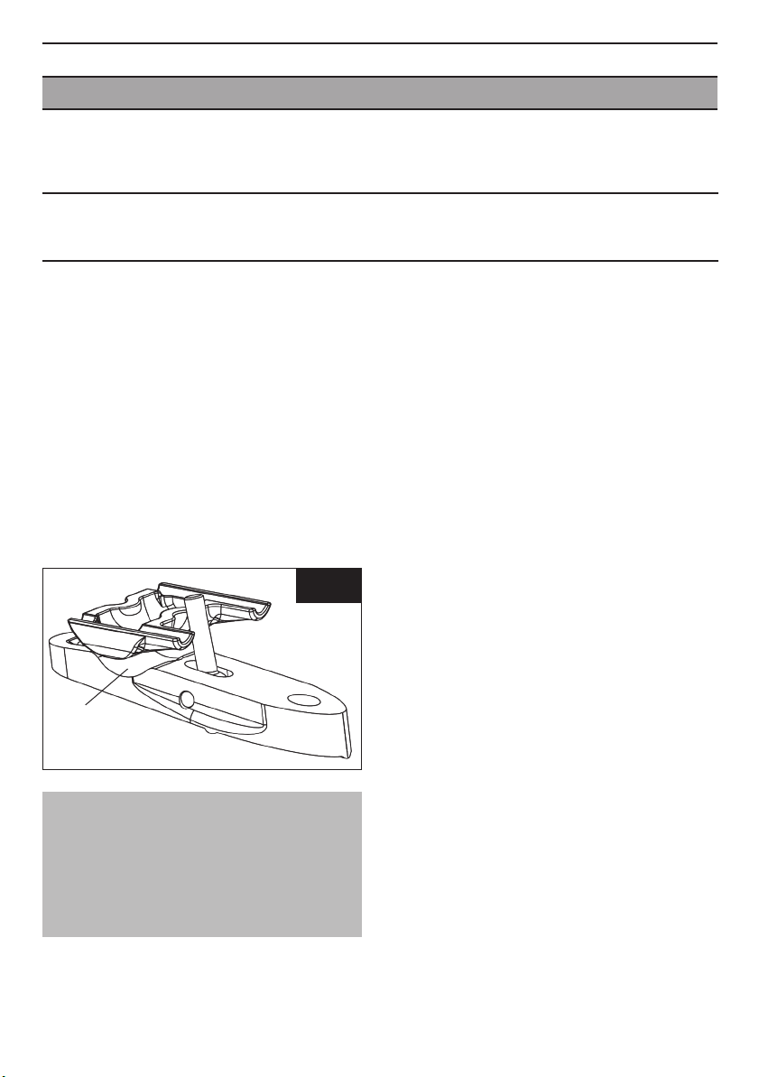
Votre cadre est livré monté avec son pédalier
ZED spécialement développé pour la piste,
sa fourche déportée (brevet LOOK) et une
potence carbone piste ainsi qu’un cintre
aéro carbone. Le cadre est livré aussi avec
sa tige de selle profilée équipée d’un chariot
en carbone.
Votre cadre est validé UCI sous la référence :
LOOK-PT91-TR, n°40863
Nous vous conseillons pour le montage
des accessoires de vous adresser à un
professionnel.
Avant toute utilisation, lisez l’intégralité
des instructions, respectez les conseils
donnés afin de profiter pleinement des
atouts de ce produit de haute qualité.
LOOK se réserve la possibilité de changer
les spécifications du produit et sans avis
préalable dans le but de l’améliorer.
FR
4
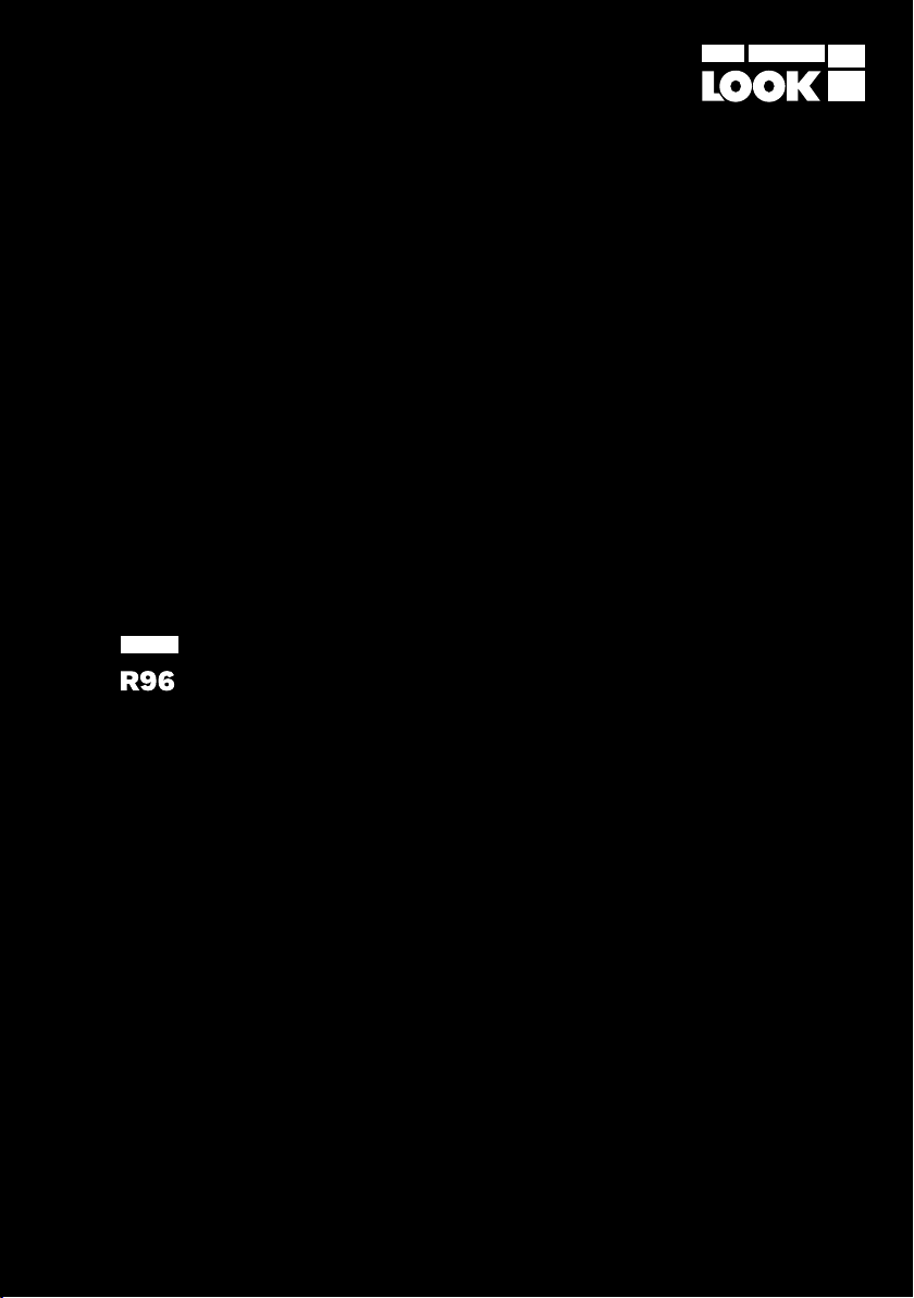
Pour le montage du pédalier ZED PISTE,
merci de vous reporter à la notice spécifique
à ce produit.

5
FR
REGLAGE DE HAUTEUR DE LA SELLEINSTALLATION DE LA FOURCHE
Le L96 est un cadre monobloc dont le tube
de selle est continu jusqu’à la selle pour
optimiser l’aérodynamisme et la rigidité tout
en diminuant le poids.
La hauteur du tube de selle a été déterminée
en fonction de vos cotes personnelles. La
hauteur est donc sur-mesure et ne doit
pas être modifiée sous peine de perte de
garantie.
Pour le montage du chariot sur le tube de
selle, veuillez vous reporter au paragraphe
correspondant. Veillez à bien respecter le
montage et les couples de serrage.
Pour information, votre hauteur de selle
(définie lors de la commande) est obtenue
grâce à l’ajout de 7 entretoises de 1mm
chacune entre le chariot carbone et
l’extrémité du tube de selle.
Vous avez la possibilité de retirer ces 7mm
d’entretoises pour diminuer jusqu’à 7 mm
la hauteur de votre selle (ou ajuster avec
une nouvelle selle) ou bien d’ajouter jusqu’à
7mm d’entretoise pour augmenter la hauteur
de votre selle (ou ajuster avec une nouvelle
selle).
Le jeu de direction ne peut être démonté
sans outils spécifiques. Veuillez faire appel
à un détaillant agréé LOOK.
1
2
3
4
5
6
7
8
9
10
11
12
1. douille à aiguille
2. piston supérieur
3. ressort de direction
4. pivot supérieur
5. butée d’extraction
6. insert alu
7. insert alu
8. pivot inférieur
9. amortisseur direct
10. piston inférieur
11. butée d’appui
12. douille à aiguille
Couple de serrage :
8Nm
Fig. 1

FR
6
TIGE DE SELLE MONTAGE DE LA TÊTE
DE TIGE DE SELLE
1. Chariot supérieur
2. Rondelle sphérique
3. Vis de serrage
4. Goupille cannelée
5. Vis M5 x 60
6. Tonneau
7. Ecrou à tête sphérique
8. Chariot inférieur
9. Vis à oeillet
10. Tête de tige de selle
11. Entretoise
12. Capot tube de selle
13. Tube de selle
1
2
3
4
5
6
7
8
9
10
11
12
13
1. Positionnez le capot (12) sur le tube de
selle.
2. Empilez les entretoises (11) sur le capot
en faisant attention au sens d’empilage :
3. Insérez les tonneaux (6) dans les trous
du tube de selle prévus à cet effet.
4. Positionnez la tête de tige de selle (10)
sur les entretoises.
5. Appliquez du frein filet type LOCTITE 243
sur les filets des 2 vis M5 x 60 (5)
6. Mettez en place ces vis dans la tête puis
les visser dans les tonneaux en place.
Vissez alternativement la vis de devant
et celle de derrière jusqu’à atteindre un
couple de serrage de 8 Nm.
Flèches vers
l’avant du vélo
Fig. 2

7
FR
MONTAGE DU CHARIOT
DE SELLE
1. Présentez la vis à œillet (9) dans la fente
de la tête de tige de selle
2. Insérez la goupille cannelée (4) dans la
vis à œillet de façon a créer un axe de
rotation entre la vis et la tête.
3. Graissez la surface de la tête de selle
prête à accueillir le chariot inférieur
(Voir fig. 3).
4. Positionnez le chariot inférieur (8) dans
son emplacement sur la tête de tige de
selle.
NOTA :
Il est possible de positionner le
chariot inférieur dans les deux sens
(excroissances vers l’avant ou vers
l’arrière) suivant le recul de selle
souhaité.
5. Positionnez le chariot supérieur (1) sur
le chariot inférieur (8) avec l’ouverture
oblongue la plus large vers l’avant.
6. Appliquez de la graisse sur les 2
surfaces concaves du chariot supérieur.
7. Appliquez du frein filet type LOCTITE 243
sur les filets de la vis à œillet.
8. Vissez l’écrou à tête sphérique (7) sur
la vis à œillet en passant l’ouverture de
9.5mm du chariot supérieur.
9. Appliquez de la graisse sur la surface
bombée de la rondelle sphérique (2).
10. Passez la vis de serrage (3) dans la
rondelle sphérique en prenant soin
d’avoir la surface plane de la rondelle
en contact avec la tête de vis.
11. Appliquez du frein filet type LOCTITE 243
sur les filets de la vis.
12. Positionnez l’écrou à tête sphérique
dans le deuxième emplacement
disponible du chariot supérieur.
13. Vissez la vis dans l’écrou en passant par
l’ouverture à l’arrière de la tête.
Zone à graisser
Fig. 3

FR
8
MONTAGE ET RÉGLAGE
DE LA SELLE
ASSEMBLAGE DE LA POTENCE
SUR LA FOURCHE
1. Mettez en place la selle en positionnant
les rails entre les 2 parties du chariot.
2. Serrez légèrement la vis de serrage.
3. Ajustez l’orientation de la selle de la
façon suivante :
- Pour basculer la selle vers l’avant :
dévisser la vis de serrage puis serrer
l’écrou à l’avant à l’aide d’une clé plate
de 8 mm.
- Pour basculer la selle vers l’arrière :
dévisser l’écrou à l’avant puis visser la
vis de serrage.
4. Ajustez le recul de la selle.
5. Serrez la vis à l’arrière de la tige de selle
à 6 Nm.
ATTENTION : Afin de garantir une bonne
tenue du frein filet, il est impératif d’attendre
2h avant toute utilisation du système
POTENCE
1
234
5
6
7
8
9
11 10
1. Cône droit
2. Vis FHCX M5x30mm
3. Tête fourche
4. Vis d’extraction M6x10
5. Vis FHCX M5x30mm
6. Cône gauche
7. Potence
8. Vis FHC M5x30mm
9. Cintre
10. Capot potence
11. Tonneau capot
1. Dégraissez les cônes (1&6), la tête de
fourche (3) et les bras de potence avec
un chiffon sec.
2. Graissez la vis d’extraction M6x10mm (4).
3. Vissezetserrez àla mainla visM6x10mm
dans le cône gauche. La tête de vis doit
être en appui sur le petit diamètre du
cône (Fig. 5).
Fig. 4

FR
9
4. Pré-positionnez les cônes dans la tête
de fourche. Un trou dans le cône droit
doit être aligné avec un taraudage dans
le cône gauche.
5. Appliquez une légère pression sur les
cônes pour qu’ils restent en position
dans la fourche (Fig. 6).
6. Positionnez la potence sur la tête de
fourche.
7. Aligner les trous de la potence avec les
trous des cônes (Fig. 7).
8. Ajustez votre position angulaire. Par
rapport à l’horizontale, les potences
peuvent varier angulairement de +20° à
-9° (Fig. 8).
9. Serrez de façon homogène chacune des
vis FHCX M5x30mm au couple de 8Nm.
Alternez des serrages coté droit et coté
gauche pour serrer de façon homogène.
Les vis droites doivent traverser le coté
droit de la potence et venir se serrer
dans le cône gauche, et inversement.
Fig. 5
Fig. 6
Fig. 7
Fig. 8

FR
10
ASSEMBLAGE DU CINTRE
SUR LA POTENCE
Diamètre de cintre autorisé : 31.8mm
Serrage sur cintre de largeur mini : 45mm
1. Dégraissez le capot (10), le cintre (9) et
la potence (7).
2. Graissez les vis M5x30 (8) sur le filetage
et la tête.
3. Positionnez le tonneau dans le capot. Le
tonneau doit se situer en dessous de la
potence (Fig. 9).
4. Pré-positionnez le cintre sur la potence.
5. Positionner la partie inférieure du capot
pourvue du tonneau dans la potence.
6. Rabattez la partie supérieure sur la
potence.
Fig. 9
Fig. 10
7. Insérez les vis de fixation capot (Fig. 10).
8. Serrez de façon homogène les 2 vis de
serrage capot au couple de 8Nm.
NOTA :
Le capot est suffisamment souple pour
pouvoir passer par dessus le diamètre
31.8mm du cintre et par dessus la potence.
Une ouverture de 33mm maximum du
capot est possible.

FR
1. Desserrez légèrement (environ 3mm)
les 6 vis FHCX sans toutefois les retirer
de l'ensemble.
2. Positionnez une clé Allen de 5mm dans
le trou central de la potence, coté droit
(Fig. 11).
3. Desserrez la vis M6x10mm centrale
jusqu'à ce que l'un des 2 cônes se
désolidarise de la tête de fourche
4. Continuez à desserrez jusqu'à ce que
le deuxième cônes se désolidarise
aussi de la tête de fourche en faisant
attention toutefois à ne pas écarter les
bras composites de la potence.
5. Lorsque les 2 cônes sont extraits, il est
alors possible de régler angulairement
la potence
6. Attention, ne pas oublier de visser de
nouveau la vis M6x10 dans le cône
gauche avant serrage de la potence sur
la fourche.
RÉGLAGE ANGULAIRE /
DÉMONTAGE POTENCE
11
MONTAGE DES ROUES
Suivez les indications de montage du
fabricant.
Nos pattes de fourche sont conçues avec
des ergots de sécurité.
Avant de rouler assurez-vous que les roues
soient fortement bloquées par le mécanisme
de blocage rapide.
Fig. 11

12
FR
Nettoyer toujours votre cadre avec du savon ou
détergent léger et de l’eau. Employer un chiffon
doux. Rincer votre cadre à l’eau et le sécher
avec un chiffon. Ne pas utiliser d’appareil de
nettoyage à haute pression, ni de produits
abrasifs. Pour éliminer les taches de goudron,
utiliser un produit pour carrosserie de voiture.
Malgrétout lesoin apportéà notrefabrication,
si un défaut apparaît ou si une réparation
est nécessaire, s’adresser toujours à votre
revendeur avec le cadre ou la fourche
accompagné(e) de la carte de garantie.
Nos cadres et nos fourches sont garantis
cinq ans à partir de la date d’achat contre
tout vice ou défaut de fabrication. La
peinture, la décoration, le vernis et tout ce
qui concerne la finition sont garantis un an.
Pour que la garantie soit valable,
enregistrez-vous sur notre site : www.
lookcycle.com
Cette garantie reste limitée à l’acheteur
initial et une preuve d’ achat est requise
(facture originale).
La garantie concerne les cadres pour tous
vices ou défauts de fabrication.
La garantie s’applique uniquement si le
cadre est assemblé conformément aux
instructions ci dessus.
La garantie ne s’applique pas aux
ATTENTION :
Inspectez toujours votre vélo avant de
l’utiliser.
Si les tubes de votre cadre LOOK ou votre
fourche ont subi n’importe quel dommage,
rapportez le vélo chez votre revendeur LOOK
pour une inspection.
Prennez connaissance des lois en vigueur
dans le pays où vous êtes.
Ce cadre étant dépourvu de tout système
de freinage indépendant du pédalier, il est
strictement réservé à un usage sur piste et
ne doit pas être utilisé sur route.
Portez toujours un casque.
GARANTIE
ENTRETIEN
SERVICE APRÈS-VENTE
dommages dus au mauvais entretien ou à
une mauvaise utilisation.
De même la garantie est caduque si le
cadre ou la fourche a subi une modification
technique du fait de l’utilisateur ou s’il a
été réparé, repeint hors d’un centre de
réparation agréé LOOK. En particulier ne
pas supprimer les ergots de sécurité des
pattes de fourche.
La garantie ne couvre pas les cas suivants:
* négligence ou entretien insuffisant
* les accidents
* les dommages accessoires et indirects
Les dépenses de montage, démontage,
temps de main d’oeuvre, emballage et
expédition du cadre ne sont pas couverts.
Ne pas percer, peindre ou revernir.
Ne pas laisser le cadre près d’une source
de chaleur.

EN
Congratulations!
You have chosen a LOOK bicycle.
Thank you for your confidence in our
products.
By choosing this LOOK bicycle, you get a
high-tech product of French design.
Your frame, fork, ZED track crank set, stem,
handlebar and seat post are identical to
those supplied to major professional teams,
are inspected throughout their construction
and will give you complete satisfaction.
Our products comply with various
international and European standards in
force.
PRESENTATION OF THE PRODUCT
Your frame has been crafted to the
specifications of the LOOK design office.
Many hours are needed for its manufacture.
Your frame comes assembled with its ZED
crankset specifically developedfor thetrack,
the offset fork (LOOK patent) and carbon
track stem and an aero carbon handlebar.
The frame also comes with its contoured
seat post fitted with a carbon carriage.
Your frame is UCI approved under reference:
LOOK-PT91-TR, no. 40863
We advise you to contact a professional,
when fitting accessories.
Before use, please read these instructions
fully and follow the advice they give, in
order to benefit fully from the features of
this top-quality product.
LOOKreservesthe right tochangeproduct
specifications without prior notice in the
interests of product improvement.
To fit the ZED TRACK crank set, please refer
to the specific instructions for this product.
13

ADJUSTING THE HEIGHT
OF THE SADDLE
INSTALLING THE FORK
The L96 is a single-piece frame. Its seat tube
is continuous to the saddle to optimize the
aerodynamics and rigidity whilst reducing
weight.
The height of the seat tube was determined
according to your personal dimensions. The
height is therefore tailor-made and must not
be modified. Otherwise the warranty will be
lost.
To fit the carriage on the seat tube, please
refer to the corresponding paragraph. Be
sure to follow the fitting procedure and
tightening torques.
For your information, your saddle height
(defined when ordering) is obtained by
adding 7 spacers of 1 mm each between
the carbon carriage and the end of the seat
tube.
You have the possibility of removing the
7mm spacers to reduce the height of your
saddle by up to 7 mm (or adjusting with a
new saddle) or adding up to 7 mm of spacers
to increase the height of your saddle (or
adjusting with a new saddle).
The steering set cannot be dismantled
without special tools. Please call an
authorized LOOK retailer.
1
2
3
4
5
6
7
8
9
10
11
12
1. needle barrel
2. upper piston
3. steering spring
4. upper hinge
5. extraction bumper
6. aluminium insert
7. aluminium insert
8. lower hinge
9. direct absorber
10. lower piston
11. bearing bumper
12. needle barrel
Torque : 8Nm
Fig. 1
14
EN

EN
SEAT POST FITTING THE
SEAT POST HEAD
1. Upper carriage
2. Spherical washer
3. Tightening bolt
4. Grooved pin
5. M5 x 60 bolt
6. Barrel
7. Spherical head nut
8. Lower carriage
9. Eye screw
10. Saddle rod head
11. Spacer
12. Seat tube cover
13. Seat tube
1
2
3
4
5
6
7
8
9
10
11
12
13
1. Place the cover (12) on the seat tube.
2. Stack the spacers (11) on the cover with
care to stacking direction:
3. Insert the barrels (6) into the holes of the
seat tube designed for that purpose.
4. Position the seat post head (10) on the
spacers.
5. Apply a LOCTITE 243 type product to the
threads of the two M5 x 60 screws (5).
6. Insert these screws into the head and
then screw them into the barrels in
place. Alternatively tighten the screw in
front and the one behind until a torque
of 8 Nm is reached.
Arrows to the front
of the bicycle
Fig. 2
15

16
EN
FITTING THE SADDLE CARRIAGE
1. Introduce the eye screw (9) in the slot of
the saddle post head.
2. Insert the grooved pin (4) into the eye
screw to create a rotation axis between
the screw and the head.
3. Grease the surface of the saddle head
ready to take the lower carriage (see
fig. 3).
4. Position the lower carriage (8) into its
housing on the saddle post head.
5. Position the upper carriage (1) over
the lower carriage (8) with the wider
rectangular opening towards the front.
NOTE:
It is possible to position the lower
carriage in either direction (protrusions
forwards or backwards) according to
the desired saddle position.
6. Apply grease to the two concave
surfaces of the upper carriage.
7. Apply a LOCTITE 243 type product to the
threads of the eye screw.
8. Screw on the spherical head nut (7) on
the eye screw via the 9.5 mm opening of
the upper carriage.
9. Apply grease to the convex surface of
the spherical washer (2).
10. Thread the clamping screw (3) into the
spherical washer, taking care to have
the flat surface of the washer in contact
with the screw head.
11. Apply a LOCTITE 243 type product to the
threads of the screw.
12. Position the spherical head nut into the
second available housing of the upper
carriage.
13. Tighten the screw into the nut via the
opening behind the head.
Area to be
greased
Fig. 3

EN
FITTING AND ADJUSTING
THE SADDLE
FITTING THE STEM
ON THE FORK
1. Fit the saddle by positioning the rails
between the two parts of the carriage.
2. Gently tighten the clamping screw.
3. Adjust the direction of the saddle as
follows:
- To tip the saddle forwards: unscrew
the clamping screw and tighten the front
nut with a 8 mm flat spanner.
- To tip the saddle backwards: unscrew
the front screw and then tighten the
clamping screw.
4. Adjust the position of the saddle.
5. Tighten the screws of the back of the
seat post to 6 Nm.
CAUTION: To ensure that the Loctite holds
well, wait 2 hours before using the system.
STEM
1
234
5
6
7
8
9
11 10
1. Right cone
2. FHCX M5x30mm screws
3. Fork head
4. M6x10 extractor screw
5. FHCX M5x30mm screws
6. Left cone
7. Stem
8. FHC M5x30 mm screws
9. Arch
10. Stem cover
11. Cover barrel
1. Degrease the cones (1 & 6), the fork
head (3) and the stem arm with a dry
cloth.
2. Grease the M6 x 10 mm extraction screw (4).
3. Screw in and hand tighten the M6 x 10
mm screw in the left cone. The screw
head should bear against the small
diameter of the cone (Fig. 5).
Fig. 4
17

18
EN
The right screws must go through the right
side of the stem and tighten into the left
cone, and vice versa.
Fig. 5
Fig. 6
Fig. 7
Fig. 8
4. Pre-position the cones in the fork head.
A hole in the right cone must be aligned
with the thread in the left cone.
5. Apply light pressure on the cones so
that they remain in position in the fork
(Fig. 6).
6. Position the stem on the fork head.
7. Align the stem holes with the holes of
the cones (Fig. 7).
8. Adjust your anglar position. Relative
to the horizontal, the stems may vary
angularly from 20° to -9° (Fig. 8).
9. Evenly tighten each FHCX M5 x 30 mm
screw to torque of 8 Nm. Alternate
tightening the right side and left side to
tighten evenly.

EN
FITTING THE HANDLEBAR
ON THE STEM
Authorized handlebar diameter: 31.8mm
Tightening on handlebar of min. width: 45 mm
1. Degrease the cover (10), the handlebar
(9) and the stem (7).
2. Grease the M5 x 30 screws (8) on the
thread and the head.
3. Position the barrel in the cover. The
barrel must be below the stem (Fig. 9).
4. Pre-position the handlebar on the stem.
5. Position the lower part of the cover with
the barrel in the stem.
6. Fold the upper part onto the stem.
Fig. 9
Fig. 10
7. Insert the cover fixing screw (Fig. 10).
8. Evenly tighten the two cover tightening
screws to torque of 8 Nm.
NOTE :
Le capot est suffisamment souple pour
pouvoir passer par dessus le diamètre
31.8mm du cintre et par dessus la potence.
Une ouverture de 33mm maximum du
capot est possible.
19

20
EN
1. Gently loosen (about 3 mm) the 6 FHCX
screws without removing them from the
assembly.
2. Position a 5 mm Allen key in the central
hole of the stem, right side (Fig. 11).
3. Loosen the M6 x 10 mm central screw
until one of the two cones disengages
from the fork head.
4. Continue loosening until the second
cone also disengages from the fork
head, being careful not to move the
composite arms away from the stem.
5. When the two cones are extracted, it is
then possible to adjust the angle of the
stem.
6. Caution - do not forget to tighten the
M6 x 10 screw again into the left cone
before tightening the stem on the fork.
ANGULAR ADJUSTMENT /
REMOVING THE STEM
FITTING THE WHEELS
Follow the manufacturer’s fiting instructions.
Our fork dropouts are designed with safety
pins.
Before cycling, make sure the wheels
are solidly locked by the quick release
mechanism.
Fig. 11

EN
Always clean your frame with gentle soap
or detergent and water. Use a soft cloth.
Rinse the frame with water and dry it with a
cloth. Do not use a high-pressure cleaner or
abrasive product. To remove tar stains, use a
car body cleaner.
Despite all the care that goes into our
manufacturing, if a defect appears or if a
repair is necessary, always take the frame
or fork and the warranty card to your dealer.
Our frames and our forks are guaranteed
free of manufacturing faults or errors for
a period of five years from the date of
purchase. Paint, decoration, varnish and
all finish items are guaranteed for one year.
To validate the warranty register on our
website: www.lookcycle.com
This warranty remains limited to the
initial purchaser and proof of purchase is
required (original bill).
Frames are guaranteed against all
manufacturing defects and faults.
The warranty applies only if the frame
was assembled in accordance with the
instructions above.
The warranty does not apply to defects
caused by poor maintenance or incorrect
IMPORTANT:
Always inspect your bicycle before
using it.
If the tubes of your LOOK frame or fork
have been subjected to any damage,
take the bicycle to your LOOK dealer for
inspection.
Be aware of the laws applying in your
country, if you ride at night. This frame
has no braking system independent from
the pedals. It is strictly restricted to use
on the track and should not be used on
the road.
Always wear a helmet.
WARRANTY
MAINTENANCE
AFTER-SALES SERVICE
use.
Similarly, the warranty is void if the frame
or fork has been technically modified by
the user or has been repaired or repainted,
other than by an approved LOOK repair
centre. In particular, do not remove the
safety drop-outs on the fork ends.
The warranty does not cover the following
cases:
* negligence or insufficient
maintenance
* accidents
* incidental or indirect damage
The costs of fitting, dismantling, labour
time, packing and shipping the frame are
not covered.
Do not drill, paint or re-varnish. Do not
leave the frame near a heat source.
21
Table of contents
Languages:
Other Look Bicycle manuals

Look
Look AERO User manual

Look
Look E-765 GRAVEL User manual

Look
Look 875 MADISON RS User manual

Look
Look 977 User manual

Look
Look 765 2020 User manual

Look
Look 695 AEROLIGHT User manual

Look
Look T20 User manual

Look
Look 795 LIGHT RS User manual

Look
Look 795 BLADE RS 2019 User manual

Look
Look 795 Blade RS User manual