6
Maintenance
Establish a schedule for inspecting all parts of the fan.
The frequency of inspection depends on the operating con-
ditions and location of the fan.
Inspect fans exhausting corrosive or contaminated air
within the first month of operation. Fans exhausting con-
taminated air (airborne abrasives) should be inspected
every three months.
Regular inspections are recommended for fans exhaust-
ing non-contaminated air.
It is recommended the following inspection be conducted
twice per year.
• Inspect bolts and setscrews for tightness. Tighten as
necessary.
• Inspect belt wear and alignment. Replace worn belts
with new belts and adjust alignment as needed. Refer
to Belt and Pulley Installation, page 3.
• Bearings should be inspected as recommended in the
Conditions Chart.
• Inspect variable inlet vanes (if supplied) for freedom of
operation and excessive wear. The vane position
should agree with the position of the control arm. As
the variable inlet vanes close, the entering air should
spin in the same direction as the wheel.
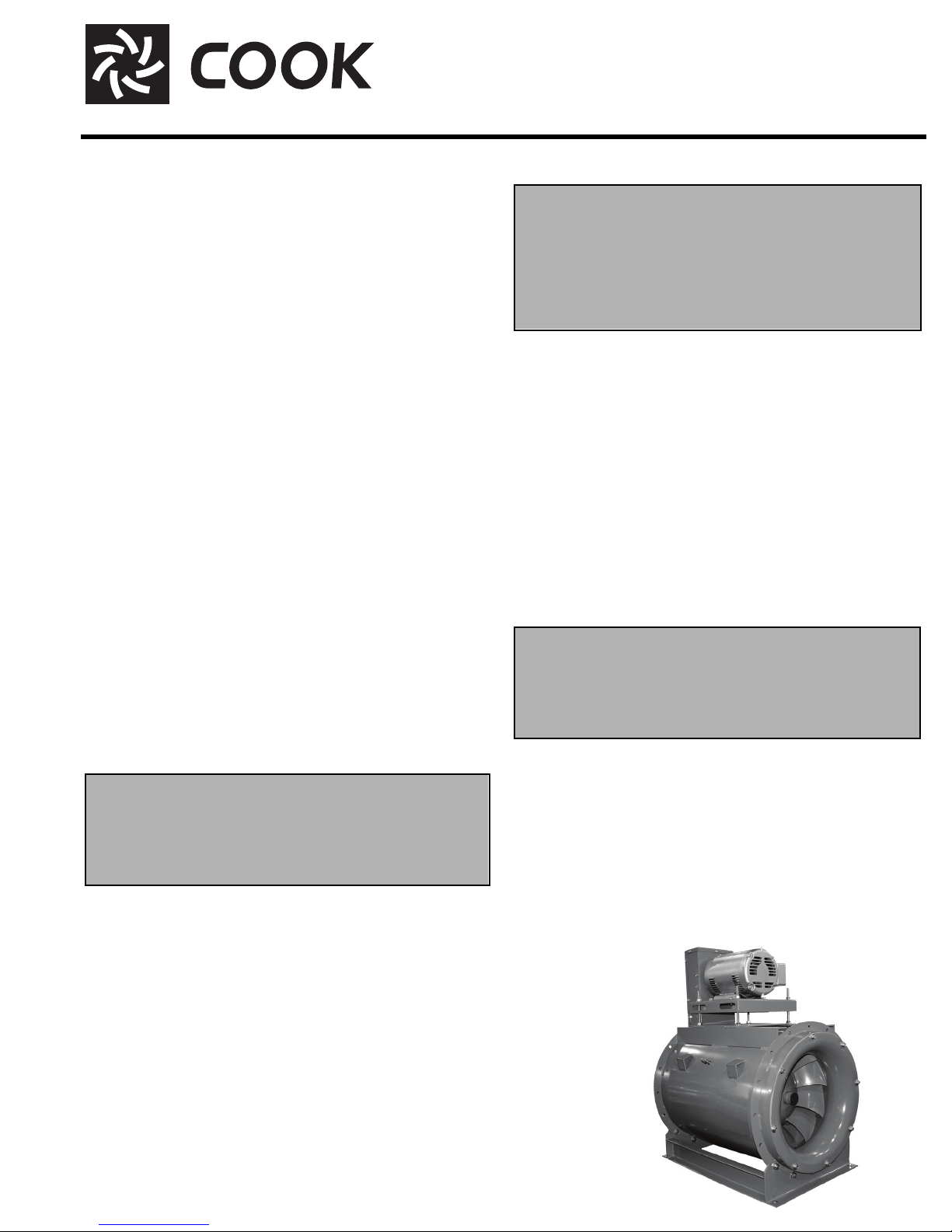
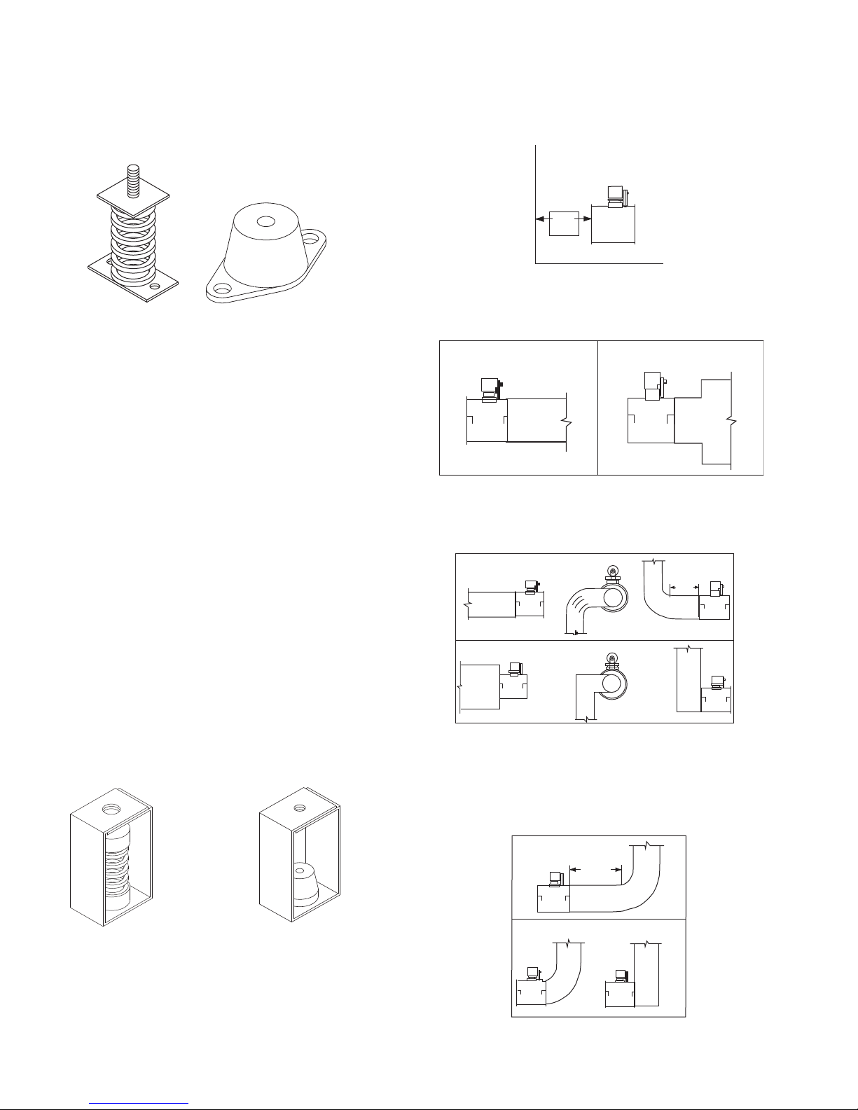
• Inspect springs and rubber isolators for deterioration
and replace as needed.
• Inspect for cleanliness. Clean exterior surfaces only.
Removing dust and grease on motor housing assures
proper motor cooling. Removing dirt from the wheel
and housing prevents imbalance and damage.
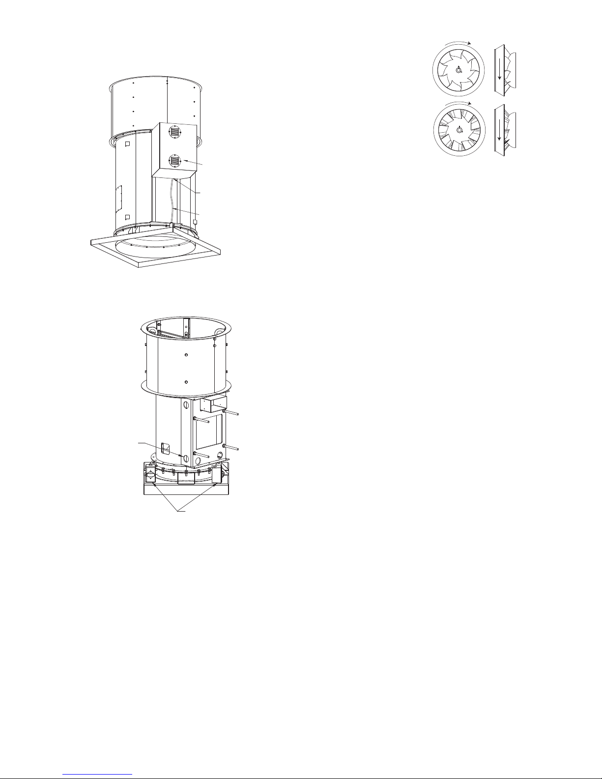
Lubrication - Fan Bearings
QMX bearings are lubricated through a grease fitting on
the outer housing and should be lubricated by the sched-
ule, Conditions Chart.
For best results, lubricate the bearing while the fan is in
operation. Pump grease in slowly until a slight bead forms
around the bearing seals. Excessive grease can burst
seals thus reducing bearing life.
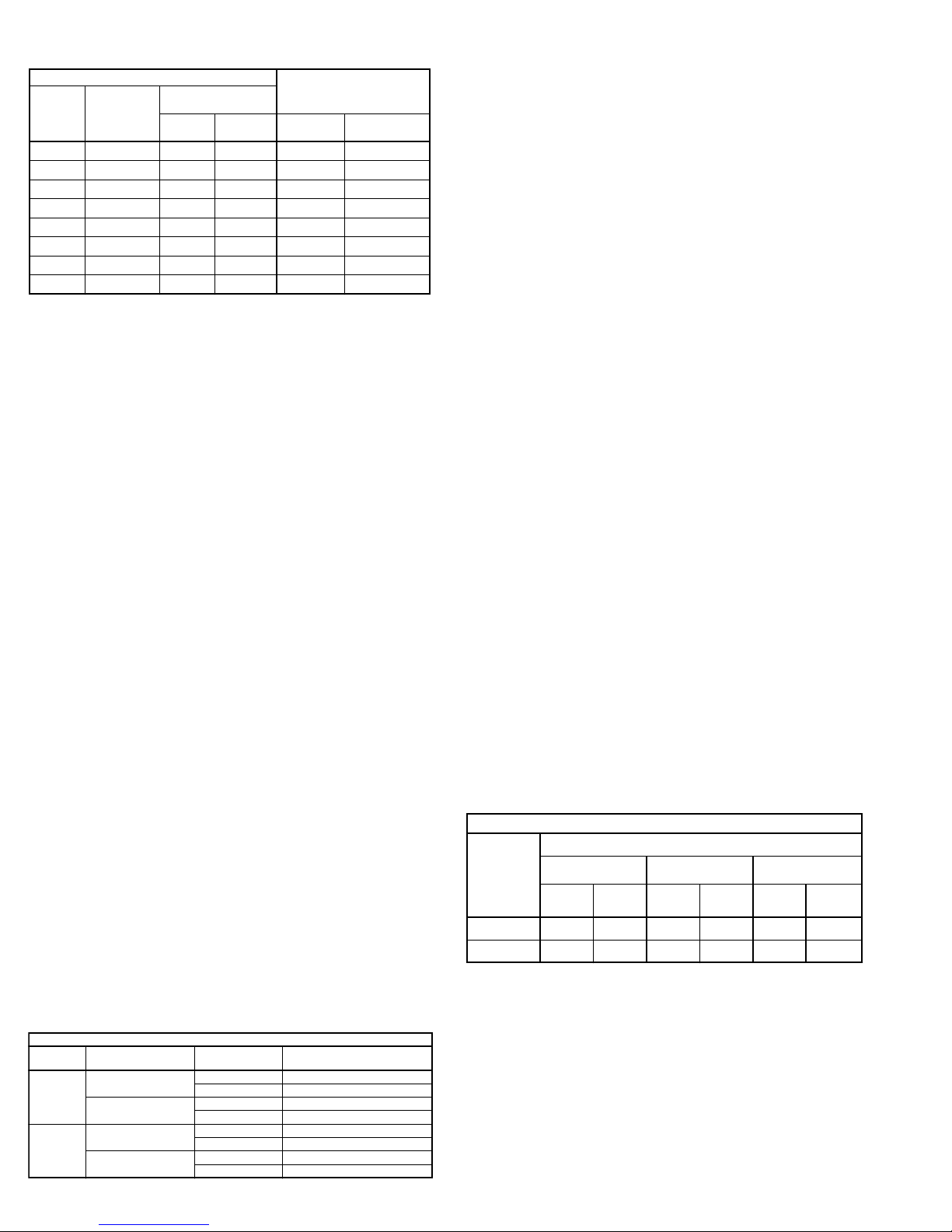
Lubrication Conditions Chart
Fan Class Fan Status Shaft Size Maximum Interval (opera-
tional hrs)
QMX
Normal Conditions
(Clean, Dry & Smooth)
> 1-1/2” 7,500
< 1-1/2” 2,000
Extreme Conditions
(Dirty/Wet/Rough)
> 1-1/2” 1,500
< 1-1/2” 400
QMX-HP
Normal Conditions
(Clean, Dry & Smooth)
> 2” 5,000
< 2” 1,000
Extreme Conditions
(Dirty/Wet/Rough)
> 2” 1,000
< 2” 200
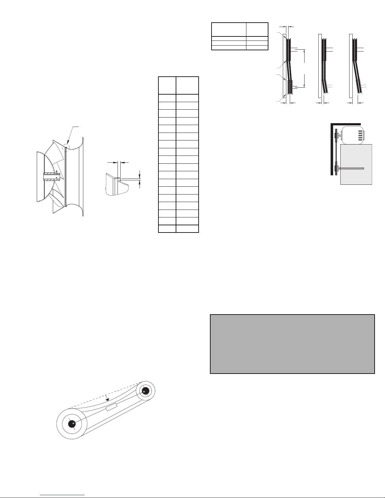
Recommended Torque for Setscrews/Bolts
Setscrews
Hold Down Bolts
Size
Key Hex
Across
Flats
Recommended
Torque
Min. Max. Size Wrench
Torque
No.10 3/32” 28 33 3/8”-16 240
1/4” 1/8” 66 80 1/2”-13 600
5/16” 5/32” 126 156 5/8”-11 1200
3/8” 3/16” 228 275 3/4”-10 2100
7/16” 7/32” 29 348 7/8”-9 2400
1/2” 1/4” 42 504 1” -8 3000
5/8” 5/16” 92 1104
3/4” 3/8” 120 1440
(IN/LB) In the event the bearing cannot be seen, use no more than
three injections with a hand-operated grease gun.
Before lubricating, the grease nipple and immediate
vicinity should be thoroughly cleaned without the use of
high pressure equipment. The grease should be supplied
slowly as the bearing rotates until fresh grease slips past
the seal. Excessive pressure should be avoided to prevent
seal damage.
Exceptions to the greasing interval chart:
• Periodic Applications (any break of one week or
more): it is recommended that full lubrication be performed
prior to each break in operation.
• Higher Temperature: it is recommended to halve the
intervals for every 30F increase in operating temperature
above 120F not to exceed 230F for standard bearings;
High Temperature bearings (optional) can operate up to
400F.
• Vertical Shaft: it is recommended that the intervals
should be halved.
Loren Cook Company uses petroleum lubricant in a lith-
ium base. Other types of grease should not be used unless
the bearings and lines have been flushed clean. If another
type of grease is used, it should be a lithium-based grease
conforming to NLGI grade 2 consistency.
A NLGI grade 2 grease is a light viscosity, low-torque,
rust-inhibiting lubricant that is water resistant. Its tempera-
ture range is from -30F to +200F and capable of intermit-
tent highs of +250F.
Lubrication - Motor Bearings
Motors are provided with prelubricated bearings. Any
lubrication instructions shown on the motor nameplate
supersede instructions below.
Motor bearings without provisions for relubrication will
operate up to 10 years under normal conditions with no
maintenance. In severe applications, high temperatures or
excessive contaminates, it is advisable to have the mainte-
nance department disassemble and lubricate the bearings
after 3 years of operation to prevent interruption of service.
For motors with provisions for relubrication, follow inter-
vals of the table below.
Motors are provided with a polyurea mineral oil NGLI #2
grease. All additions to the motor bearings are to be with a
compatible grease such as Exxon Mobil Polyrex EM and
Chevron SRI.
The above intervals should be reduced to half for vertical
shaft installations.
Motor Services
Should the motor prove defective within a one-year
period, contact your local Loren Cook representative or
your nearest authorized electric motor service representa-
tive.
Relubrication Intervals
Service
Conditions
NEMA Frame Size
Up to and
including 184T 213T-365T 404T and larger
1800 RPM
and less
Over 1800
RPM
1800 RPM
and less
Over 1800
RPM
1800 RPM
and less
Over 1800
RPM
Standard 3 yrs. 6 months 2 yrs. 6 months 1 yr. 3 months
Severe 1 yr. 3 months 1 yr. 3 months 6 months 1 months